EP1188947A2 - Sicherheitseinrichtung zu einem Aufzug - Google Patents
Sicherheitseinrichtung zu einem Aufzug Download PDFInfo
- Publication number
- EP1188947A2 EP1188947A2 EP01810846A EP01810846A EP1188947A2 EP 1188947 A2 EP1188947 A2 EP 1188947A2 EP 01810846 A EP01810846 A EP 01810846A EP 01810846 A EP01810846 A EP 01810846A EP 1188947 A2 EP1188947 A2 EP 1188947A2
- Authority
- EP
- European Patent Office
- Prior art keywords
- friction
- safety device
- elevator
- carbon
- friction body
- Prior art date
- Legal status (The legal status is an assumption and is not a legal conclusion. Google has not performed a legal analysis and makes no representation as to the accuracy of the status listed.)
- Granted
Links
Images


Classifications
-
- F—MECHANICAL ENGINEERING; LIGHTING; HEATING; WEAPONS; BLASTING
- F16—ENGINEERING ELEMENTS AND UNITS; GENERAL MEASURES FOR PRODUCING AND MAINTAINING EFFECTIVE FUNCTIONING OF MACHINES OR INSTALLATIONS; THERMAL INSULATION IN GENERAL
- F16D—COUPLINGS FOR TRANSMITTING ROTATION; CLUTCHES; BRAKES
- F16D69/00—Friction linings; Attachment thereof; Selection of coacting friction substances or surfaces
- F16D69/02—Composition of linings ; Methods of manufacturing
- F16D69/023—Composite materials containing carbon and carbon fibres or fibres made of carbonizable material
-
- F—MECHANICAL ENGINEERING; LIGHTING; HEATING; WEAPONS; BLASTING
- F16—ENGINEERING ELEMENTS AND UNITS; GENERAL MEASURES FOR PRODUCING AND MAINTAINING EFFECTIVE FUNCTIONING OF MACHINES OR INSTALLATIONS; THERMAL INSULATION IN GENERAL
- F16D—COUPLINGS FOR TRANSMITTING ROTATION; CLUTCHES; BRAKES
- F16D69/00—Friction linings; Attachment thereof; Selection of coacting friction substances or surfaces
- F16D69/02—Composition of linings ; Methods of manufacturing
Definitions
- the present invention relates to a safety device to an elevator with at least one in the elevator shaft permanently installed elevator guide rail and with a Brake part that has at least one friction body with at least has a friction surface which to the guide rail Braking the elevator can be pressed, the friction body a fiber-reinforced, ceramic as the friction material Has composite material, the silicon carbide and as Reinforcing component contains carbon fibers, as well as a Process for producing such a friction body.
- An emergency brake that is independent of the service brake or emergency braking device.
- Such an emergency brake is designed as a safety gear that, in an emergency, i.e. at Exceeding a predetermined maximum speed of the Car, by pressing on friction linings Guide rails in the elevator shaft with one for yourself people who are in the elevator or car Deceleration braked and in the braked, stationary Holds position securely.
- Such conventional friction linings as described for example in GB-A-2 274827, have a structure of the sliding surface which contains a graphite phase, a steadite phase, a cementite phase and a pearlite phase.
- ceramic brake pads for elevator emergency brakes have recently been proposed, the main component of which is silicon nitride.
- US-A-5,503,257 discloses an elevator safety device comprising ceramic brake parts; aluminum oxide, silicon nitride or zirconium oxide is specified for the ceramic material.
- a brake body for elevator emergency braking devices which has a braking surface and a multiplicity of braking parts which are embedded in the braking surface and protrude above it.
- These protruding brake parts are constructed of a composite material containing a ceramic base material which is selected from the group consisting of silicon nitride or titanium boride, sialon and silicon carbide and comprises not less than 10% by weight of at least one ceramic material selected from the group consisting of Silicon carbide whiskers and silicon carbide platelets exist.
- these brake shoes and their friction linings contain minimum proportions of SiC whiskers (needle-shaped fibers up to a few ⁇ m in length) or SiC platelets (platelet-shaped particles on a micrometer scale), a certain strengthening of the ceramics and a slight increase in fracture toughness are achieved.
- these brake parts can contain 10 to 55% by volume of long fibers made of SiC, Si 3 N 4 , C or tungsten, which are then arranged perpendicular to the surface of the lining.
- their amplification effects are very small. Wear and brake abrasion mean that the whisker or platelet particles, which are respirable due to their small size, can be absorbed by humans through inhalation.
- the present invention has for its object to develop a safety device for an elevator of the type described in such a way that it meets the requirements for emergency equipment for elevators, the maximum permissible speeds of up to 1500 meters per minute (corresponds 25 m / s), where temperatures of over 1000 ° C are reached when the car is braked in an emergency.
- the object is achieved in a safety device of the type mentioned at the outset in that the composite material comprises a matrix of silicon carbide and carbon, in that the reinforcing component is formed exclusively from carbon fibers which have a minimum length of 10 mm, and in that the volume content of carbon fibers in the friction body between 30% and 70%.
- a safety device is characterized in particular by the carbon fibers reinforcing the friction body and having a length of 10 mm or more; Reinforcement components in the form of whiskers or platelets are therefore not required, so that in the event of braking in the event of an emergency braking, no health-damaging dusts occur as abrasion.
- the carbon fibers forming the reinforcing component are embedded in a matrix of silicon carbide and carbon.
- the volume content of carbon fibers in the friction body between 30% and 70% ensures that the fracture toughness and thermal shock resistance are sufficiently high, with a volume content of carbon fibers in the lower region being preferred if extremely low wear rates and high thermal conductivity are to be achieved , while a volume content of carbon fibers is to be used in the upper area when particularly high demands are placed on the mechanical stability of the composite material.
- the proportion of carbon fibers in the friction body is determined due to the required mechanical strength and thermal shock resistance, the with increasing fiber content increase.
- a minimum silicon carbide content is required Generate sufficient friction and wear resistance necessary.
- Volume contents of carbon fibers in the lower Range are preferable when driving speeds moderate or the friction linings dimensioned accordingly thick can be. High fiber contents are then to be used when extreme driving speeds are achieved should or if the friction linings are very thin for reasons of space must be carried out.
- the carbon fibers are arranged in the friction bodies in the form of layers and / or knitted fabrics stacked on top of one another;
- the carbon fibers are oriented at least in the area of the friction surface in such a way that they run parallel to them.
- This fiber orientation enables the high bending moments that occur when the pads suddenly hit the guide rail in an emergency and when the car is at a standstill with extremely high surface pressures, which can be up to 100 / MPa. It is precisely through this measure that large-area linings can also be produced in one piece, ie a large number of individual, small friction bodies can be dispensed with.
- these friction bodies can be processed into circular blanks in addition to rectangular linings, and fastening bores, transverse or longitudinal grooves can be made without disadvantages to the durability of these friction bodies. As a result, all conventional designs can be used for the installation of such friction bodies in safety gear.
- the friction body of the safety device into a core part and at least one die Friction surface comprising friction part can be divided.
- the core part and the friction part can be different Requirements are adjusted, i.e. the core part can for high strength and toughness of the friction body be designed while the friction part is specific Requirements when engaging in the guide rail in the Emergency is designed, i.e. the friction part will be on tribological behavior (constant friction coefficient, wear and Thermal conductivity) optimized.
- the individual layers that make up such a friction body can be built up by reaction siliciding be connected to each other. This is before the ceramization in the connection area between the layers a C-rich joining paste introduced in the following Siliconization with the liquid silicon to silicon carbide responding.
- a preferred layer structure comprises three layers, whereby on the one hand high ceramic contents in the area close to the friction surface of the friction body can be realized and on the other hand nevertheless a sufficient mechanical strength of the Friction body with a strength-optimized layer high fiber content can be guaranteed. Due to the different levels of carbon fibers stretch these two layers differ in thickness when heated off, so that possibly high tensile stresses in the vicinity of the friction surface Area can lead to failure. To avoid this there will be an additional third between the two layers Layer introduced, their expansion behavior to be interpreted in this way is that critical tensile stresses avoided or on a tolerable measure can be reduced. Especially with three Layers can be divided into friction and core parts Composite material with economically justifiable effort getting produced.
- the SiC content should the matrix from the core area of the friction body to Increase friction surface, i.e. who converted more Areas are outside so that the SiC content is higher there.
- the depressions should preferably be transverse to the rubbing direction, or, alternatively, at an angle of 30 ° to 60 ° run to the rubbing direction; is a favorable angle about 45 °. Furthermore, the depressions should have a width of Have 1 to 5 mm to absorb enough abrasion can. The area of the depressions in the friction surface should be ⁇ 30% of the area of the total friction area.
- a layer containing Si and SiC on the friction surface can increase the wear resistance against uncoated friction bodies. However, care should be taken to ensure that the adhesion of this ceramic layer is sufficiently high even at high temperatures. Layer thicknesses of up to 0.2 mm are preferred, since thicker layers tend to flake off and thus fail the friction layer.
- An advantageous fiber volume content of the composite material is at least 50%; Values of 50% or above mean that particularly high strength and fracture toughness can be achieved.
- the SiC content of the composite material is at least 20 Mass% fixed, this value covering the entire Friction body relates and a lower limit for the area of Represents friction surface.
- Carbon fibers which are formed from bundles of at least 1000 individual filaments with a diameter of the individual filaments of the order of 5 to 15 ⁇ m have the advantage that there is a macroscopically uniform SiC distribution in the composite material.
- this makes it possible to produce the friction bodies cost-effectively, since a large number of commercially available semi-finished fibers with these dimensions are available.
- the composite material should have a bending strength of at least 50 MPa.
- a composite material for the friction bodies has proven to be preferred, which is formed by liquid siliconizing a carbon-carbon body, which is produced by pyrolysis of a phenolic resin-bonded, carbon fiber-reinforced green body. With such a procedure, friction bodies can be produced which on the one hand have sufficiently high C-fiber fractions and on the other hand have sufficiently high SiC fractions. With this process, in particular, thermal pre-treatment of the fibers can be used to set different C or SiC fractions between areas close to the friction surface and the core area.
- a preferred composite material for the friction body can by 40 to 45 mass% SiC, 2 to 6 mass% Si and 49 to 58% by mass of C and C fibers can be characterized.
- the friction body should be symmetrical Middle plane, based on the thickness of the friction body, built become.
- a friction body was built up from a matrix consisting of 95% by weight silicon carbide and carbon and a fiber reinforcement made of layered carbon fiber fabrics with a fiber orientation of the carbon fibers in directions of 0 ° and 90 °.
- the carbon fibers were HTA fibers from Akzo, Wuppertal, with a filament count of 3000.
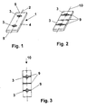
- Such a friction body is shown in FIG. 1 and is designated by reference number 1.
- This friction body 1 has a length of 120 mm and a width of 40 mm and a thickness of 8 mm.
- the respective mounting hole 3 has a stepped cross section, such that the head of a mounting screw or rivet can be used in the wide diameter range, such that it does not protrude beyond the friction surface 4.
- a friction body 1, as shown in FIG. 1, is manufactured in three steps. First, a CFRP green body bound with phenolic resin is produced in an autoclave with a fiber volume content of 50-55%. This is followed by pyrolysis of the CFRP green body at temperatures up to 1650 ° C. In the third step, the porous carbon / carbon material formed during the pyrolysis is impregnated with liquid silicon at a silicate temperature of at least 1420 ° C.
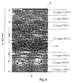
- FIGS. 4 and 5 The microstructure of the friction body is shown in FIGS. 4 and 5 shown, Figure 4 is a cross section perpendicular to the Friction surface 4 of the friction body of Figure 1 shows while the Figure 5 is a plan view of the friction surface 4 of the friction body 1 of Figure 1 shows. FIG. 4 is enlarged 100 times, while Figure 5 shows a 15x magnification.
- the carbon fibers 6 are clearly shown in the two figures to recognize the, as on the basis of the cross section of FIG can be seen are aligned parallel to the friction surface 4.
- the white and light areas show silicon carbide encased the individual carbon fibers or the gaps fills. As a result, are on the top of the friction surface SiC and C phases always engaged at the same time, the C parts predominate in terms of volume and mass.
- Figure 5 is the woven structure of the carbon fiber framework recognizable with fiber orientations below 0 ° and 90 ° to each other (the surface is sanded).
- the length of the The fibers used were exact in this embodiment as long as the geometrical dimensions of the friction body, i.e. 120 mm in the 0 ° direction and 40 mm in the 90 ° direction.
- a CFRP green body is produced using the resin injection process with a fiber volume content of approx. 60%; the individual carbon fabric layers were at different Pretreatment temperatures of 600 ° C, 750 ° C, 900 ° C and 1100 ° C before resin infiltration under inert conditions outsourced for about 20 minutes.
- the individual layers were 0.25 mm thick and symmetrical to the central plane. A total of 26 layers were present (see Figure 6).
- the CFRP green body thus constructed was then added Pyrolyzed temperatures up to 1650 ° C.
- the due to the pyrolysis of porous carbon / carbon material with liquid silicon a temperature of 1650 ° C.
- the layer structure in the thickness direction of the Friction body 1 shows, i.e. perpendicular to the friction surface 4, are the areas of the differently pretreated carbon fabric layers to recognize.
- the carbon fibers in the central area designated by the reference number 7, those that have been thermally aged at 600 ° C while the carbon fibers in areas near the surface, are designated by the reference number 8.
- the aging temperatures were from the middle level, with the Reference numeral 11 denotes, or from the central area to Edge area increased from 600 ° C to 1100 ° C.
- a friction body according to the embodiment 2 (Figure 6) is for example for particularly high and prefer constant friction values.
- FIG. 2 shows the friction lining as shown in FIG. 1 is provided with additional grooves 9 which are perpendicular to Direction of friction, indicated by the arrow 10, run.
- the Grooves 9 have a width of 2 mm and a depth of 2 mm. Overall, are shown in Figures 2 and 3 Friction body 1 three such grooves 9 available.
- the grooves 9 prevent smearing of the friction surface 4 of the friction body 1 and ensure a defined state of friction, i.e. Wear particles generated during emergency braking can store in the grooves 9 and influence the Coefficient of friction not negative.
- the wear particles are primarily metallic in nature as abrasion from the metallic guide rails into which the friction body 1 intervention.
Landscapes
- Engineering & Computer Science (AREA)
- General Engineering & Computer Science (AREA)
- Mechanical Engineering (AREA)
- Chemical & Material Sciences (AREA)
- Composite Materials (AREA)
- Materials Engineering (AREA)
- Braking Arrangements (AREA)
- Electrical Discharge Machining, Electrochemical Machining, And Combined Machining (AREA)
- Spinning Or Twisting Of Yarns (AREA)
- Centrifugal Separators (AREA)
- Maintenance And Inspection Apparatuses For Elevators (AREA)
Abstract
Description
Um den steigenden Anforderungen gerecht zu werden, wurden in neuerer Zeit keramische Bremsbeläge für Aufzugnotbremsen vorgeschlagen, deren Hauptbestandteil Siliziumnitrid ist.
In der US-A-5,503,257 wird eine Aufzugsicherheitsvorrichtung angegeben, die keramische Bremsteile umfaßt; für das Keramikmaterial ist Aluminiumoxid, Siliziumnitrid oder Zirkonoxid angegeben.
Die beschriebenen keramischen Bremsteile aus Aluminiumoxid, Siliziumnitrid oder Zirkonoxid sind, bezogen auf die Trägerplatte, von kleinerer Abmessung und formschlüssig bzw. verklebt in die Aufnahmen der Trägerplatte eingelassen. Aufgrund der unterschiedlichen Ausdehnungsverhalten zwischen den keramischen Bremsteilen und der metallischen Trägerplatte muß bei den hohen Reibflächentemperaturen mit einer Verspannung bzw. einem Lockern der Bremsteile gerechnet werden. Dies führt u.U. zum Ausfall der gesamten Bremseinrichtung durch abgescherte bzw. gebrochene Bremsteile.
Der Einsatz von Bremsteilen mit größerer flächenmäßiger Erstreckung (z.B. plattenförmige Bremsteile) ist aufgrund der unzureichenden Schadenstoleranz bei der auftretenden Biegebeanspruchung nicht möglich.
Ausgehend von dem vorstehend beschriebenen Stand der Technik liegt der vorliegenden Erfindung die Aufgabe zugrunde, eine Sicherheitseinrichtung für einen Aufzug der eingangs beschriebenen Art derart weiterzubilden, daß sie den Anforderungen an Noteinrichtungen bei Aufzügen, die maximal zulässige Geschwindigkeiten von bis zu 1500 Meter pro Minute (entspricht 25 m/s) erreichen, wo beim Abbremsen der Fahrkörbe im Notfall Temperaturen an der Notbremseinrichtung von über 1000°C erreicht werden, gerecht werden.
Gelöst wird die Aufgabe bei einer Sicherheitseinrichtung der eingangs angegebenen Art dadurch, daß der Verbundwerkstoff eine Matrix aus Siliziumkarbid und Kohlenstoff umfaßt, daß die Verstärkungskomponente ausschließlich aus Kohlenstofffasern gebildet ist, die eine Mindestlänge von 10 mm aufweisen, und daß der Volumengehalt an Kohlenstofffasern im Reibkörper zwischen 30% und 70% beträgt. Eine solche Sicherheitseinrichtung zeichnet sich insbesondere durch die den Reibkörper verstärkenden Kohlenstofffasern mit einer Länge von 10 mm oder darüber aus; Verstärkungskomponenten in Form von Whiskern oder Platelets sind somit nicht erforderlich, so daß im Bremsfall bei einer Notbremsung keine gesundheitsschädigenden Stäube als Abrieb auftreten. Die die Verstärkungskomponente bildenden Kohlenstofffasern sind in einer Matrix aus Siliziumkarbid und Kohlenstoff eingebettet. Durch den Volumengehalt an Kohlenstofffasern im Reibkörper zwischen 30% und 70% ist gewährleistet, daß eine genügend hohe Bruchzähigkeit und Thermoschockbeständigkeit gegeben ist, wobei ein Volumengehalt an Kohlenstofffasern im unteren Bereich dann zu bevorzugen ist, wenn extrem niedrige Verschleißraten und eine hohe Wärmeleitfähigkeit erzielt werden sollen, während ein Volumengehalt an Kohlenstofffasern im oberen Bereich dann einzusetzen ist, wenn besonders hohe Anforderungen an die mechanische Stabilität des Verbundwerkstoffes gestellt sind.
Aufgrund der hohen Bruchzähigkeit lassen sich diese Reibkörper, neben rechteckigen Belägen, auch zu kreisförmigen Ronden verarbeiten, und Befestigungsbohrungen, Quer- oder Längsnuten können ohne Nachteile auf die Haltbarkeit dieser Reibkörper eingebracht werden. Dadurch sind alle konventionellen Konstruktionen für den Einbau von solchen Reibkörpern in Fangvorrichtungen verwendbar.
Ein vorteilhafter Faservolumengehalt des Verbundwerkstoffs beträgt mindestens 50%; Werte von 50% oder darüber führen dazu, daß eine besonders hohe Festigkeit und Bruchzähigkeit erzielt werden kann.
Um hohe Festigkeitsniveaus für die auftretenden, schlagartigen Belastungen zu erzielen, Sicherheitsreserven zu haben und großflächige Reibkörper herstellen zu können, sollte der Verbundwerkstoff eine Biegefestigkeit von mindestens 50 MPa aufweisen.
Als Verbundwerkstoff für die Reibkörper hat sich ein solcher als bevorzugt erwiesen, der durch Flüssigsilizieren eines Kohlenstoff-Kohlenstoff-Körpers gebildet ist, der durch Pyrolyse eines phenolharzgebundenen, kohlenstofffaserverstärkten Grünkörpers erzeugt ist. Mit einer solchen Verfahrensweise können Reibkörper hergestellt werden, die einerseits genÜgend hohe C-Faser-Anteile und andererseits ausreichend hohe SiC-Anteile aufweisen. Speziell mit diesem Verfahren lassen sich durch thermische Vorbehandlung der Fasern unterschiedliche C- bzw. SiC-Anteile zwischen reibflächennahen Bereichen und dem Kernbereich einstellen.
Ein solcher Reibkörper ist in Figur 1 dargestellt und mit dem Bezugszeichen 1 bezeichnet. Dieser Reibkörper 1 besitzt eine Länge von 120 mm und eine Breite von 40 mm sowie eine Dicke von 8 mm. Auf der Mittellinie 2 liegend sind zwei Befestigungslöcher 3 mit ihrer Achse senkrecht zur Reibfläche 4 verlaufend vorgesehen. Diese Befestigungslöcher sind mit ihrer Achse von der Schmalseite 5 des Reibkörpers 1 jeweils 25 mm beabstandet. Das jeweilige Befestigungsloch 3 besitzt einen abgestuften Querschnitt, derart, daß in den weiten Durchmesserbereich der Kopf einer Befestigungsschraube oder -niete eingesetzt werden kann, derart, daß er nicht über die Reibfläche 4 vorsteht.
Zunächst wird ein mit Phenolharz gebundener CFK-Grünkörper mit einem Faservolumengehalt von 50 -55% im Autoklaven hergestellt.
Danach erfolgt eine Pyrolyse des CFK-Grünkörpers bei Temperaturen bis zu 1650°C.
Im dritten Schritt erfolgt eine Imprägnierung des während der Pyrolyse entstandenen porösen Kohlenstoff/Kohlenstoff-Werkstoffes mit flüssigem Silizium bei einer Siliziertemperatur von mindestens 1420°C.
- Dichte: 2,0 g/cm3
- Offene Porosität < 2%
- Phasenanteile in Masse-%: ca. 40% SiC, ca. 5% Si und ca. 55% C und C-Fasern
- Kurzbiegefestigkeit: 120 MPa.
- Dichte: 2,0 g/cm3
- Offene Porosität < 2%
- Faseranteile in Masse-%: ca. 45% SiC, ca. 5% Si und ca. 50% C und C-Fasern
- Kurzbiegefestigkeit: 55 MPa.
Claims (13)
- Sicherheitseinrichtung zu einem Aufzug mit mindestens einer im Aufzugsschacht fest installierten Aufzugsführungsschiene und mit einem Bremsteil, das mindestens einen Reibkörper mit mindestens einer Reibfläche aufweist, die an die Führungsschiene zur Abbremsung des Aufzugs anpressbar ist, wobei der Reibkörper als Reibwerkstoff einen faserverstärkten, keramischen Verbundwerkstoff aufweist, der Siliziumkarbid und als Verstärkungskomponente Kohlenstofffasern enthält,
dadurch gekennzeichnet, dass der Verbundwerkstoff eine Matrix aus Siliziumkarbid und Kohlenstoff umfasst, dass die Verstärkungskomponente aus Kohlenstofffasern (6; 7; 8) gebildet ist, die eine Mindestlänge von 10 mm aufweisen, und dass der Volumengehalt an Kohlenstofffasern (6; 7; 8) im Reibkörper zwischen 30% und 70% beträgt. - Sicherheitseinrichtung nach Anspruch 1, dadurch gekennzeichnet, dass die Kohlenstofffasern in Form von schichtweise übereinandergestapelten Geweben und/oder Gewirken angeordnet sind, wobei die Kohlenstofffasern (6; 7; 8) wenigstens im Bereich der Reibfläche (4) derart orientiert sind, dass sie parallel dazu verlaufen.
- Sicherheitseinrichtung nach Anspruch 1, dadurch gekennzeichnet, dass der SiC-Gehalt der Matrix im reibflächennahen Bereich des Reibkörpers (1) höher ist als in dessen reibflächenfernen Bereich.
- Sicherheitseinrichtung nach Anspruch 1, dadurch gekennzeichnet, dass der Reibkörper (1) in einen Kernteil und mindestens einen die Reibfläche umfassenden Reibteil unterteilt ist.
- Sicherheitseinrichtung nach Anspruch 1, dadurch gekennzeichnet, dass der Reibkörper (1) aus einzelnen Schichten aufgebaut ist und diese Schichten durch Reaktionssilizierung miteinander verbunden sind, wobei vorzugsweise drei Schichten vorgesehen sind.
- Sicherheitseinrichtung nach Anspruch 3, dadurch gekennzeichnet, dass der SiC-Gehalt der Matrix vom Kernbereich des Reibkörpers (1) zur Reibfläche (4) hin zunimmt.
- Sicherheitseinrichtung nach Anspruch 1, dadurch gekennzeichnet, dass der Reibkörper (1) in dem Reibflächenbereich Vertiefungen(9), insbesondere in Form von Nuten, aufweist.
- Sicherheitseinrichtung nach Anspruch 7, dadurch gekennzeichnet, dass die Vertiefungen (9) quer zur Reibrichtung oder unter einem Winkel von 30° bis 60°, vorzugsweise unter einem Winkel von 45° zur Reibrichtung (10), verlaufen.
- Sicherheitseinrichtung nach Anspruch 1, dadurch gekennzeichnet, dass auf der Reibfläche (4) eine Si ind SiC enthaltende Schicht aufgebracht ist, wobei diese Schicht vorzugsweise eine Dicke von 0,01 bis 0,2 mm aufweist.
- Sicherheitseinrichtung nach Anspruch 1, dadurch gekennzeichnet, dass der Verbundwerkstoff einen Faservolumengehalt von mindestens 50% und/oder eine offene Porosität von ≦ 10% aufweist.
- Sicherheitseinrichtung nach Anspruch 1, dadurch gekennzeichnet, dass die Kohlenstofffasern aus Bündeln von mindestens 1000 Einzelfilamenten gebildet sind, wobei die Einzelfilamente einen Durchmesser zwischen 5 bis 15 µm aufweisen.
- Sicherheitseinrichtung nach Anspruch 1, dadurch gekennzeichnet, dass im Verbundwerkstoff dessen Phasenanteile, in Massenprozent,betragen .a) SiC: 40 bis 45 %b) Si: 2 bis 6 %c) C und C-Fasern: 49 bis 58%
- Verfahren zum Herstellen eines Reibkörpers (1) für eine Aufzugbremse, der an die Führungsschiene eines Aufzugs anpressbar ist, wobei der Reibkörper (1) als Reibwerkstoff einen faserverstärkten, keramischen Verbundwerkstoff aufweist, der Siliziumkarbid und Kohlenstoff umfasst,
dadurch gekennzeichnet, dass
der Verbundwerkstoff durch Flüssigsilizieren eines Kohlenstoff-Kohlenstoff-Körpers hergestellt wird, der durch Pyrolyse eines phenolharzgebundenen, kohlenstofffaserverstärkten Grünkörpers erzeugt wurde.
Applications Claiming Priority (2)
| Application Number | Priority Date | Filing Date | Title |
|---|---|---|---|
| DE10045881A DE10045881A1 (de) | 2000-09-14 | 2000-09-14 | Sicherheitseinrichtung für einen Aufzug |
| DE10045881 | 2000-09-14 |
Publications (3)
| Publication Number | Publication Date |
|---|---|
| EP1188947A2 true EP1188947A2 (de) | 2002-03-20 |
| EP1188947A3 EP1188947A3 (de) | 2007-06-13 |
| EP1188947B1 EP1188947B1 (de) | 2012-01-11 |
Family
ID=7656470
Family Applications (1)
| Application Number | Title | Priority Date | Filing Date |
|---|---|---|---|
| EP01810846A Expired - Lifetime EP1188947B1 (de) | 2000-09-14 | 2001-09-03 | Sicherheitseinrichtung zu einem Aufzug |
Country Status (14)
| Country | Link |
|---|---|
| US (1) | US6668985B2 (de) |
| EP (1) | EP1188947B1 (de) |
| JP (1) | JP2002114466A (de) |
| CN (1) | CN1164470C (de) |
| AT (1) | ATE541138T1 (de) |
| AU (1) | AU784019B2 (de) |
| BR (1) | BR0104029B1 (de) |
| CA (1) | CA2357180C (de) |
| DE (1) | DE10045881A1 (de) |
| ES (1) | ES2380808T3 (de) |
| IL (1) | IL145091A (de) |
| MY (1) | MY126898A (de) |
| SG (1) | SG111026A1 (de) |
| ZA (1) | ZA200107555B (de) |
Cited By (3)
| Publication number | Priority date | Publication date | Assignee | Title |
|---|---|---|---|---|
| EP1382879A1 (de) * | 2002-07-16 | 2004-01-21 | Sgl Carbon Ag | Reibmaterial, insbesondere Reibbelag einer Nassreibungskupplung |
| EP1508718A1 (de) * | 2003-08-20 | 2005-02-23 | Sgl Carbon Ag | Kupplungsbeläge aus faserverstärkten keramischen Werkstoffen |
| EP2725257A1 (de) | 2012-10-23 | 2014-04-30 | Inventio AG | Bremsschuh für eine Aufzugsanlage |
Families Citing this family (18)
| Publication number | Priority date | Publication date | Assignee | Title |
|---|---|---|---|---|
| DE10060566B4 (de) * | 2000-12-01 | 2005-09-08 | Dr.Ing.H.C. F. Porsche Ag | Reibkörper aus siliziuminfiltriertem, kohlenstofffaserverstärktem porösen Kohlenstoff, Verfahren zum Herstellen eines solchen Reibkörpers und Verwendung eines solchen Reibkörpers |
| DE10233729B4 (de) * | 2002-07-24 | 2006-01-26 | Sgl Carbon Ag | Faserverstärkte keramische Bremsbeläge |
| JP2004211888A (ja) * | 2002-12-24 | 2004-07-29 | Inventio Ag | ケーブルを制動するブレーキシュー |
| DE10346499A1 (de) * | 2003-10-02 | 2005-04-28 | Sgl Carbon Ag | Reibpaarung für Feststellbremsen in Kraftfahrzeugen |
| DE10359484A1 (de) * | 2003-12-18 | 2005-07-14 | Deutsches Zentrum für Luft- und Raumfahrt e.V. | Verfahren zur Herstellung eines Bauteils aus einem Faserverbundwerkstoff und Faserverbundwerkstoff |
| DE102006044848A1 (de) * | 2006-07-03 | 2008-01-10 | Deutsches Zentrum für Luft- und Raumfahrt e.V. | Verfahren zur Herstellung eines carbidkeramischen Kontaktkörpers und carbidkeramischer Kontaktkörper |
| US20100072002A1 (en) * | 2006-08-29 | 2010-03-25 | Honeywell International Inc. | Aircraft brake using mixed carbon composite friction couple with different degrees of graphitization for improved rejected take off and wear performance |
| JP4561778B2 (ja) * | 2007-06-04 | 2010-10-13 | 株式会社日立製作所 | エレベーター用非常止め装置 |
| CN101070395B (zh) * | 2007-06-20 | 2010-05-26 | 中南大学 | 炭/炭-碳化硅复合材料刹车闸瓦闸片的制造方法 |
| JP5427682B2 (ja) * | 2010-04-16 | 2014-02-26 | 株式会社日立製作所 | 非常止め装置及びそれを用いたエレベーター |
| FI123238B (fi) | 2011-02-02 | 2012-12-31 | Kone Corp | Menetelmä ja järjestely nostokoneiston jarrun jarrutusvoiman uudistamiseksi |
| JP5374541B2 (ja) * | 2011-04-28 | 2013-12-25 | 株式会社日立製作所 | エレベーター用非常停止装置の制動子、エレベーター用非常停止装置及びエレベーター |
| CN104271485A (zh) * | 2012-04-30 | 2015-01-07 | 奥的斯电梯公司 | 用于制动器的定制摩擦 |
| WO2014035382A1 (en) | 2012-08-29 | 2014-03-06 | Otis Elevator Company | Friction brake assembly with an abradable metal foam brake pad |
| CN107980035B (zh) * | 2015-04-10 | 2019-12-24 | 奥的斯电梯公司 | 电梯安全钳对准系统和方法 |
| DE202015102837U1 (de) * | 2015-06-01 | 2016-09-06 | Wittur Holding Gmbh | Aufzugsbrems- und/oder Fangvorrichtung mit geschweißtem Bremsbelag |
| CN107082336A (zh) * | 2016-02-16 | 2017-08-22 | 上海三菱电梯有限公司 | 电梯用紧急制动装置的制动楔块、紧急制动装置及电梯 |
| US10981679B2 (en) | 2017-08-04 | 2021-04-20 | Rocket Lab Usa, Inc. | Satellite deployer door release mechanism |
Family Cites Families (25)
| Publication number | Priority date | Publication date | Assignee | Title |
|---|---|---|---|---|
| US4790052A (en) * | 1983-12-28 | 1988-12-13 | Societe Europeenne De Propulsion | Process for manufacturing homogeneously needled three-dimensional structures of fibrous material |
| DE3762544D1 (de) * | 1986-02-05 | 1990-06-07 | Europ Propulsion | Reibungssystem aus zusammengesetzten feuerfesten materialien. |
| US4815572A (en) * | 1987-07-24 | 1989-03-28 | Parker-Hannifin Corporation | Brake system with improved brake material |
| JPH0813713B2 (ja) * | 1990-10-11 | 1996-02-14 | 東芝セラミックス株式会社 | SiC被覆C/C複合材 |
| JPH07107413B2 (ja) * | 1991-05-21 | 1995-11-15 | 日信工業株式会社 | 車両用ディスクブレーキ |
| US5363943A (en) * | 1991-10-15 | 1994-11-15 | Honda Giken Kogyo Kabushiki Kaisha | Disk brake apparatus for vehicle |
| US5398784A (en) * | 1991-10-29 | 1995-03-21 | Nissin Kogyo Co., Ltd. | Brake friction composite with reinforcing pyrolytic carbon and thermosetting resin |
| KR0130481B1 (ko) | 1993-02-03 | 1998-04-10 | 가나이 쯔도무 | 엘리베이터용 비상정지장치 및 엘리베이터 |
| JP2803974B2 (ja) | 1993-07-30 | 1998-09-24 | 三菱電機株式会社 | エレベーターの非常止め装置 |
| DE4438456C2 (de) * | 1994-10-28 | 2002-07-11 | Deutsch Zentr Luft & Raumfahrt | Reibeinheit |
| US5546880A (en) * | 1994-12-29 | 1996-08-20 | The Bf Goodrich Company | Annular filamentary structures and methods of making |
| JP3792758B2 (ja) * | 1995-09-06 | 2006-07-05 | 株式会社東芝 | エレベータ非常停止装置用ブレーキシュー、エレベータ非常停止装置および非常停止機能付エレベータ |
| GB9525622D0 (en) * | 1995-12-15 | 1996-02-14 | Sab Wabco Bromborough Limited | Friction engaging device |
| JP3294143B2 (ja) * | 1996-09-10 | 2002-06-24 | 株式会社東芝 | エレベータ非常停止装置用ブレーキシュー、エレベータ用非常停止装置および非常停止機能を有するエレベータ |
| JPH10121325A (ja) * | 1996-10-14 | 1998-05-12 | Toray Ind Inc | 炭素繊維用前駆体繊維束とその製造方法および炭素繊維の製造方法 |
| EP0835853A1 (de) | 1996-10-14 | 1998-04-15 | Societe Europeenne De Propulsion | Reibelement aus Kohlenstoff/Kohlenstoff-Siliciumcarbidverbundwerkstoff und Verfahren zu seiner Herstellung |
| FR2756277B1 (fr) * | 1996-11-28 | 1999-04-02 | Europ Propulsion | Materiau composite a matrice ceramique et renfort en fibres sic et procede pour sa fabrication |
| US6364072B1 (en) * | 1997-04-28 | 2002-04-02 | Alliedsignal Bremsbelag Gmbh | Sintered material for a magnetic track brake |
| DE19721473C2 (de) * | 1997-05-22 | 2002-11-14 | Deutsch Zentr Luft & Raumfahrt | Reibeinheit zum reibenden Eingriff mit einem Gegenkörper sowie Verfahren zur Herstellung einer solchen Reibeinheit |
| DE19727587C2 (de) * | 1997-06-28 | 2002-10-24 | Daimler Chrysler Ag | Bremseinheit aus Bremsscheibe und Bremsbelag |
| DE19727586C2 (de) * | 1997-06-28 | 2002-10-24 | Daimler Chrysler Ag | Bremseinheit aus Bremsscheibe und Bremsbelag |
| US5979615A (en) * | 1997-11-06 | 1999-11-09 | Otis Elevator Company | Carbon--carbon composite elevator safety brakes |
| JP2000081062A (ja) * | 1998-09-08 | 2000-03-21 | Ngk Insulators Ltd | ブレーキ用部材 |
| DE19861035C2 (de) * | 1998-04-06 | 2000-11-30 | Daimler Chrysler Ag | Faserverbundwerkstoff und Verfahren zu dessen Herstellung |
| JP2000072550A (ja) * | 1998-08-24 | 2000-03-07 | Toshiba Corp | 摺動部材 |
-
2000
- 2000-09-14 DE DE10045881A patent/DE10045881A1/de not_active Ceased
-
2001
- 2001-08-21 SG SG200105104A patent/SG111026A1/en unknown
- 2001-08-23 IL IL14509101A patent/IL145091A/xx not_active IP Right Cessation
- 2001-09-03 EP EP01810846A patent/EP1188947B1/de not_active Expired - Lifetime
- 2001-09-03 ES ES01810846T patent/ES2380808T3/es not_active Expired - Lifetime
- 2001-09-03 JP JP2001265350A patent/JP2002114466A/ja active Pending
- 2001-09-03 AT AT01810846T patent/ATE541138T1/de active
- 2001-09-05 CN CNB011312874A patent/CN1164470C/zh not_active Expired - Lifetime
- 2001-09-06 US US09/947,829 patent/US6668985B2/en not_active Expired - Lifetime
- 2001-09-11 MY MYPI20014262 patent/MY126898A/en unknown
- 2001-09-12 CA CA002357180A patent/CA2357180C/en not_active Expired - Lifetime
- 2001-09-13 AU AU72053/01A patent/AU784019B2/en not_active Expired
- 2001-09-13 BR BRPI0104029-4A patent/BR0104029B1/pt not_active IP Right Cessation
- 2001-09-13 ZA ZA200107555A patent/ZA200107555B/xx unknown
Non-Patent Citations (1)
| Title |
|---|
| None |
Cited By (4)
| Publication number | Priority date | Publication date | Assignee | Title |
|---|---|---|---|---|
| EP1382879A1 (de) * | 2002-07-16 | 2004-01-21 | Sgl Carbon Ag | Reibmaterial, insbesondere Reibbelag einer Nassreibungskupplung |
| EP1508718A1 (de) * | 2003-08-20 | 2005-02-23 | Sgl Carbon Ag | Kupplungsbeläge aus faserverstärkten keramischen Werkstoffen |
| US7413701B2 (en) | 2003-08-20 | 2008-08-19 | Sgl Carbon Ag | Clutch linings comprising fiber-reinforced ceramic materials |
| EP2725257A1 (de) | 2012-10-23 | 2014-04-30 | Inventio AG | Bremsschuh für eine Aufzugsanlage |
Also Published As
| Publication number | Publication date |
|---|---|
| CN1164470C (zh) | 2004-09-01 |
| HK1046304A1 (en) | 2003-01-03 |
| EP1188947B1 (de) | 2012-01-11 |
| JP2002114466A (ja) | 2002-04-16 |
| AU7205301A (en) | 2002-03-21 |
| ATE541138T1 (de) | 2012-01-15 |
| ZA200107555B (en) | 2002-05-14 |
| BR0104029B1 (pt) | 2011-09-06 |
| CA2357180A1 (en) | 2002-03-14 |
| CN1343620A (zh) | 2002-04-10 |
| ES2380808T3 (es) | 2012-05-18 |
| US20020029944A1 (en) | 2002-03-14 |
| MY126898A (en) | 2006-10-31 |
| EP1188947A3 (de) | 2007-06-13 |
| CA2357180C (en) | 2009-07-28 |
| BR0104029A (pt) | 2002-05-07 |
| DE10045881A1 (de) | 2002-05-08 |
| IL145091A0 (en) | 2002-06-30 |
| AU784019B2 (en) | 2006-01-12 |
| SG111026A1 (en) | 2005-05-30 |
| US6668985B2 (en) | 2003-12-30 |
| IL145091A (en) | 2005-11-20 |
Similar Documents
| Publication | Publication Date | Title |
|---|---|---|
| EP1188947B1 (de) | Sicherheitseinrichtung zu einem Aufzug | |
| EP0797555B1 (de) | Reibeinheit | |
| DE69726604T3 (de) | Reibungselement aus kohlenstoff/kohlenstoff-siliziumcarbid-verbundmaterial und verfahren zu seiner herstellung | |
| DE10060566B4 (de) | Reibkörper aus siliziuminfiltriertem, kohlenstofffaserverstärktem porösen Kohlenstoff, Verfahren zum Herstellen eines solchen Reibkörpers und Verwendung eines solchen Reibkörpers | |
| EP1054765B1 (de) | Verfahren zur herstellung eines faserverbundwerkstoffs | |
| DE69631968T2 (de) | Vorrichtung für reibungskupplung | |
| DE19636223C2 (de) | Verfahren zum dauerhaften Verbinden von wenigstens zwei Bauteilkomponenten zu einem Formkörper | |
| EP1649183B1 (de) | Synchronring | |
| DE69837677T2 (de) | Faserverbundwerkstoff und verfahren zur herstellung | |
| DE29610498U1 (de) | Fahrzeugbrems- bzw. Fahrzeugkupplungsscheibe aus C-C/SiC-Werkstoff | |
| DE69209717T2 (de) | Bremsscheibe für Fahrzeuge | |
| DE69806333T2 (de) | Faserverbundwerkstoff und seine Verwendung | |
| DE69925789T3 (de) | Bauteil für Bremsen | |
| DE3602132A1 (de) | Gleit- oder reibelement mit funktionsteil aus keramischem werkstoff mit eingelagertem stabilisator sowie verfahren zu seiner herstellung | |
| WO1998053219A1 (de) | Reibeinheit zum reibenden eingriff mit einem gegenkörper sowie verfahren zur herstellung einer solchen reibeinheit | |
| EP1508718B1 (de) | Kupplungsbeläge aus faserverstärkten keramischen Werkstoffen | |
| EP1141572B2 (de) | Bremseinheit | |
| DE102016101684A1 (de) | Reibwerterhöhende einlage zum kraftschlüssigen verbinden von bauteilen, verfahren zur herstellung einer reibwerterhöhenden einlage und verfahren zur herstellung eines pressverbands | |
| DE102009022112A1 (de) | Bremsbelag, Verfahren zur Herstellung eines solchen Bremsbelags sowie Bremseinheit umfassend einen solchen Bremsbelag | |
| EP1536156B1 (de) | Reibpaarungen für Feststellbremsen in Kraftfahrzeugen | |
| EP2458241B1 (de) | Verfahren zur Herstellung eines Reibelementes | |
| AT527691B1 (de) | Vormaterial für einen Faser-Keramik-Verbund | |
| EP3032126B1 (de) | Keramische Bremsscheibe | |
| WO2021213696A1 (de) | Reibeinheit | |
| DE8914883U1 (de) | Schichtkörper aus Kohlenstoffilz und Graphitfolie |
Legal Events
| Date | Code | Title | Description |
|---|---|---|---|
| PUAI | Public reference made under article 153(3) epc to a published international application that has entered the european phase |
Free format text: ORIGINAL CODE: 0009012 |
|
| AK | Designated contracting states |
Kind code of ref document: A2 Designated state(s): AT BE CH CY DE DK ES FI FR GB GR IE IT LI LU MC NL PT SE TR |
|
| AX | Request for extension of the european patent |
Free format text: AL;LT;LV;MK;RO;SI |
|
| PUAL | Search report despatched |
Free format text: ORIGINAL CODE: 0009013 |
|
| AK | Designated contracting states |
Kind code of ref document: A3 Designated state(s): AT BE CH CY DE DK ES FI FR GB GR IE IT LI LU MC NL PT SE TR |
|
| AX | Request for extension of the european patent |
Extension state: AL LT LV MK RO SI |
|
| 17P | Request for examination filed |
Effective date: 20071211 |
|
| AKX | Designation fees paid |
Designated state(s): AT BE CH CY DE DK ES FI FR GB GR IE IT LI LU MC NL PT SE TR |
|
| 17Q | First examination report despatched |
Effective date: 20080131 |
|
| GRAP | Despatch of communication of intention to grant a patent |
Free format text: ORIGINAL CODE: EPIDOSNIGR1 |
|
| GRAS | Grant fee paid |
Free format text: ORIGINAL CODE: EPIDOSNIGR3 |
|
| GRAA | (expected) grant |
Free format text: ORIGINAL CODE: 0009210 |
|
| AK | Designated contracting states |
Kind code of ref document: B1 Designated state(s): AT BE CH CY DE DK ES FI FR GB GR IE IT LI LU MC NL PT SE TR |
|
| REG | Reference to a national code |
Ref country code: GB Ref legal event code: FG4D Free format text: NOT ENGLISH |
|
| REG | Reference to a national code |
Ref country code: CH Ref legal event code: EP |
|
| REG | Reference to a national code |
Ref country code: AT Ref legal event code: REF Ref document number: 541138 Country of ref document: AT Kind code of ref document: T Effective date: 20120115 |
|
| REG | Reference to a national code |
Ref country code: IE Ref legal event code: FG4D |
|
| REG | Reference to a national code |
Ref country code: DE Ref legal event code: R096 Ref document number: 50116033 Country of ref document: DE Effective date: 20120308 |
|
| REG | Reference to a national code |
Ref country code: NL Ref legal event code: VDEP Effective date: 20120111 |
|
| REG | Reference to a national code |
Ref country code: ES Ref legal event code: FG2A Ref document number: 2380808 Country of ref document: ES Kind code of ref document: T3 Effective date: 20120518 |
|
| REG | Reference to a national code |
Ref country code: HK Ref legal event code: GR Ref document number: 1046304 Country of ref document: HK |
|
| PG25 | Lapsed in a contracting state [announced via postgrant information from national office to epo] |
Ref country code: NL Free format text: LAPSE BECAUSE OF FAILURE TO SUBMIT A TRANSLATION OF THE DESCRIPTION OR TO PAY THE FEE WITHIN THE PRESCRIBED TIME-LIMIT Effective date: 20120111 |
|
| REG | Reference to a national code |
Ref country code: IE Ref legal event code: FD4D |
|
| PG25 | Lapsed in a contracting state [announced via postgrant information from national office to epo] |
Ref country code: PT Free format text: LAPSE BECAUSE OF FAILURE TO SUBMIT A TRANSLATION OF THE DESCRIPTION OR TO PAY THE FEE WITHIN THE PRESCRIBED TIME-LIMIT Effective date: 20120511 Ref country code: FI Free format text: LAPSE BECAUSE OF FAILURE TO SUBMIT A TRANSLATION OF THE DESCRIPTION OR TO PAY THE FEE WITHIN THE PRESCRIBED TIME-LIMIT Effective date: 20120111 Ref country code: GR Free format text: LAPSE BECAUSE OF FAILURE TO SUBMIT A TRANSLATION OF THE DESCRIPTION OR TO PAY THE FEE WITHIN THE PRESCRIBED TIME-LIMIT Effective date: 20120412 |
|
| PG25 | Lapsed in a contracting state [announced via postgrant information from national office to epo] |
Ref country code: CY Free format text: LAPSE BECAUSE OF FAILURE TO SUBMIT A TRANSLATION OF THE DESCRIPTION OR TO PAY THE FEE WITHIN THE PRESCRIBED TIME-LIMIT Effective date: 20120111 |
|
| PG25 | Lapsed in a contracting state [announced via postgrant information from national office to epo] |
Ref country code: DK Free format text: LAPSE BECAUSE OF FAILURE TO SUBMIT A TRANSLATION OF THE DESCRIPTION OR TO PAY THE FEE WITHIN THE PRESCRIBED TIME-LIMIT Effective date: 20120111 Ref country code: SE Free format text: LAPSE BECAUSE OF FAILURE TO SUBMIT A TRANSLATION OF THE DESCRIPTION OR TO PAY THE FEE WITHIN THE PRESCRIBED TIME-LIMIT Effective date: 20120111 Ref country code: IE Free format text: LAPSE BECAUSE OF FAILURE TO SUBMIT A TRANSLATION OF THE DESCRIPTION OR TO PAY THE FEE WITHIN THE PRESCRIBED TIME-LIMIT Effective date: 20120111 |
|
| PLBE | No opposition filed within time limit |
Free format text: ORIGINAL CODE: 0009261 |
|
| STAA | Information on the status of an ep patent application or granted ep patent |
Free format text: STATUS: NO OPPOSITION FILED WITHIN TIME LIMIT |
|
| PG25 | Lapsed in a contracting state [announced via postgrant information from national office to epo] |
Ref country code: IT Free format text: LAPSE BECAUSE OF FAILURE TO SUBMIT A TRANSLATION OF THE DESCRIPTION OR TO PAY THE FEE WITHIN THE PRESCRIBED TIME-LIMIT Effective date: 20120111 |
|
| 26N | No opposition filed |
Effective date: 20121012 |
|
| REG | Reference to a national code |
Ref country code: DE Ref legal event code: R097 Ref document number: 50116033 Country of ref document: DE Effective date: 20121012 |
|
| PG25 | Lapsed in a contracting state [announced via postgrant information from national office to epo] |
Ref country code: MC Free format text: LAPSE BECAUSE OF NON-PAYMENT OF DUE FEES Effective date: 20120930 |
|
| REG | Reference to a national code |
Ref country code: CH Ref legal event code: PL |
|
| PG25 | Lapsed in a contracting state [announced via postgrant information from national office to epo] |
Ref country code: LI Free format text: LAPSE BECAUSE OF NON-PAYMENT OF DUE FEES Effective date: 20120930 Ref country code: CH Free format text: LAPSE BECAUSE OF NON-PAYMENT OF DUE FEES Effective date: 20120930 |
|
| REG | Reference to a national code |
Ref country code: AT Ref legal event code: MM01 Ref document number: 541138 Country of ref document: AT Kind code of ref document: T Effective date: 20120903 |
|
| PGFP | Annual fee paid to national office [announced via postgrant information from national office to epo] |
Ref country code: TR Payment date: 20130822 Year of fee payment: 13 |
|
| PG25 | Lapsed in a contracting state [announced via postgrant information from national office to epo] |
Ref country code: AT Free format text: LAPSE BECAUSE OF NON-PAYMENT OF DUE FEES Effective date: 20120903 |
|
| PG25 | Lapsed in a contracting state [announced via postgrant information from national office to epo] |
Ref country code: LU Free format text: LAPSE BECAUSE OF NON-PAYMENT OF DUE FEES Effective date: 20120903 |
|
| PGFP | Annual fee paid to national office [announced via postgrant information from national office to epo] |
Ref country code: FR Payment date: 20140919 Year of fee payment: 14 Ref country code: ES Payment date: 20140926 Year of fee payment: 14 |
|
| PGFP | Annual fee paid to national office [announced via postgrant information from national office to epo] |
Ref country code: BE Payment date: 20140919 Year of fee payment: 14 |
|
| REG | Reference to a national code |
Ref country code: FR Ref legal event code: ST Effective date: 20160531 |
|
| PG25 | Lapsed in a contracting state [announced via postgrant information from national office to epo] |
Ref country code: FR Free format text: LAPSE BECAUSE OF NON-PAYMENT OF DUE FEES Effective date: 20150930 |
|
| REG | Reference to a national code |
Ref country code: ES Ref legal event code: FD2A Effective date: 20161026 |
|
| PG25 | Lapsed in a contracting state [announced via postgrant information from national office to epo] |
Ref country code: ES Free format text: LAPSE BECAUSE OF NON-PAYMENT OF DUE FEES Effective date: 20150904 |
|
| PG25 | Lapsed in a contracting state [announced via postgrant information from national office to epo] |
Ref country code: BE Free format text: LAPSE BECAUSE OF NON-PAYMENT OF DUE FEES Effective date: 20150930 |
|
| PG25 | Lapsed in a contracting state [announced via postgrant information from national office to epo] |
Ref country code: TR Free format text: LAPSE BECAUSE OF NON-PAYMENT OF DUE FEES Effective date: 20150903 |
|
| PGFP | Annual fee paid to national office [announced via postgrant information from national office to epo] |
Ref country code: GB Payment date: 20200925 Year of fee payment: 20 |
|
| PGFP | Annual fee paid to national office [announced via postgrant information from national office to epo] |
Ref country code: DE Payment date: 20201127 Year of fee payment: 20 |
|
| REG | Reference to a national code |
Ref country code: DE Ref legal event code: R071 Ref document number: 50116033 Country of ref document: DE |
|
| REG | Reference to a national code |
Ref country code: GB Ref legal event code: PE20 Expiry date: 20210902 |
|
| PG25 | Lapsed in a contracting state [announced via postgrant information from national office to epo] |
Ref country code: GB Free format text: LAPSE BECAUSE OF EXPIRATION OF PROTECTION Effective date: 20210902 |