EP1188038B1 - Apparatus and method for monitoring wear in seat materials of valves - Google Patents
Apparatus and method for monitoring wear in seat materials of valves Download PDFInfo
- Publication number
- EP1188038B1 EP1188038B1 EP00941587A EP00941587A EP1188038B1 EP 1188038 B1 EP1188038 B1 EP 1188038B1 EP 00941587 A EP00941587 A EP 00941587A EP 00941587 A EP00941587 A EP 00941587A EP 1188038 B1 EP1188038 B1 EP 1188038B1
- Authority
- EP
- European Patent Office
- Prior art keywords
- valve
- range
- act
- open
- adjusting
- Prior art date
- Legal status (The legal status is an assumption and is not a legal conclusion. Google has not performed a legal analysis and makes no representation as to the accuracy of the status listed.)
- Expired - Lifetime
Links
- 239000000463 material Substances 0.000 title claims abstract description 60
- 238000000034 method Methods 0.000 title claims abstract description 41
- 238000012544 monitoring process Methods 0.000 title claims description 11
- 238000012545 processing Methods 0.000 claims description 17
- 230000008569 process Effects 0.000 description 14
- 230000001276 controlling effect Effects 0.000 description 6
- 238000012423 maintenance Methods 0.000 description 6
- 230000002159 abnormal effect Effects 0.000 description 4
- 238000013459 approach Methods 0.000 description 4
- 238000010586 diagram Methods 0.000 description 4
- 239000007788 liquid Substances 0.000 description 4
- 230000007704 transition Effects 0.000 description 4
- 230000008901 benefit Effects 0.000 description 2
- 230000001105 regulatory effect Effects 0.000 description 2
- 238000010008 shearing Methods 0.000 description 2
- 230000006978 adaptation Effects 0.000 description 1
- 230000004075 alteration Effects 0.000 description 1
- 238000004458 analytical method Methods 0.000 description 1
- 230000006399 behavior Effects 0.000 description 1
- 239000000872 buffer Substances 0.000 description 1
- 230000008859 change Effects 0.000 description 1
- 238000012512 characterization method Methods 0.000 description 1
- 235000013365 dairy product Nutrition 0.000 description 1
- 230000006870 function Effects 0.000 description 1
- 238000009434 installation Methods 0.000 description 1
- 239000012464 large buffer Substances 0.000 description 1
- 238000004519 manufacturing process Methods 0.000 description 1
- 235000015205 orange juice Nutrition 0.000 description 1
- 230000001052 transient effect Effects 0.000 description 1
- 230000003313 weakening effect Effects 0.000 description 1
Images


Classifications
-
- F—MECHANICAL ENGINEERING; LIGHTING; HEATING; WEAPONS; BLASTING
- F16—ENGINEERING ELEMENTS AND UNITS; GENERAL MEASURES FOR PRODUCING AND MAINTAINING EFFECTIVE FUNCTIONING OF MACHINES OR INSTALLATIONS; THERMAL INSULATION IN GENERAL
- F16K—VALVES; TAPS; COCKS; ACTUATING-FLOATS; DEVICES FOR VENTING OR AERATING
- F16K37/00—Special means in or on valves or other cut-off apparatus for indicating or recording operation thereof, or for enabling an alarm to be given
- F16K37/0075—For recording or indicating the functioning of a valve in combination with test equipment
- F16K37/0083—For recording or indicating the functioning of a valve in combination with test equipment by measuring valve parameters
-
- F—MECHANICAL ENGINEERING; LIGHTING; HEATING; WEAPONS; BLASTING
- F16—ENGINEERING ELEMENTS AND UNITS; GENERAL MEASURES FOR PRODUCING AND MAINTAINING EFFECTIVE FUNCTIONING OF MACHINES OR INSTALLATIONS; THERMAL INSULATION IN GENERAL
- F16K—VALVES; TAPS; COCKS; ACTUATING-FLOATS; DEVICES FOR VENTING OR AERATING
- F16K37/00—Special means in or on valves or other cut-off apparatus for indicating or recording operation thereof, or for enabling an alarm to be given
- F16K37/0075—For recording or indicating the functioning of a valve in combination with test equipment
-
- Y—GENERAL TAGGING OF NEW TECHNOLOGICAL DEVELOPMENTS; GENERAL TAGGING OF CROSS-SECTIONAL TECHNOLOGIES SPANNING OVER SEVERAL SECTIONS OF THE IPC; TECHNICAL SUBJECTS COVERED BY FORMER USPC CROSS-REFERENCE ART COLLECTIONS [XRACs] AND DIGESTS
- Y10—TECHNICAL SUBJECTS COVERED BY FORMER USPC
- Y10T—TECHNICAL SUBJECTS COVERED BY FORMER US CLASSIFICATION
- Y10T137/00—Fluid handling
- Y10T137/8158—With indicator, register, recorder, alarm or inspection means
- Y10T137/8225—Position or extent of motion indicator
- Y10T137/8242—Electrical
-
- Y—GENERAL TAGGING OF NEW TECHNOLOGICAL DEVELOPMENTS; GENERAL TAGGING OF CROSS-SECTIONAL TECHNOLOGIES SPANNING OVER SEVERAL SECTIONS OF THE IPC; TECHNICAL SUBJECTS COVERED BY FORMER USPC CROSS-REFERENCE ART COLLECTIONS [XRACs] AND DIGESTS
- Y10—TECHNICAL SUBJECTS COVERED BY FORMER USPC
- Y10T—TECHNICAL SUBJECTS COVERED BY FORMER US CLASSIFICATION
- Y10T137/00—Fluid handling
- Y10T137/8158—With indicator, register, recorder, alarm or inspection means
- Y10T137/8359—Inspection means
Definitions
- This invention relates generally to monitoring valves, and more particularly to monitoring wear in seat materials of valves.
- a valve is a mechanical device by which the flow of liquid, gas, or lose material in bulk may be started, stopped, or regulated by opening, shutting, or partially obstructing one or more passageways.
- a valve is typically fitted with seat materials, such as rubber. With repeated usage, seat materials may be worn away.
- seat materials may be worn away because of the flow of liquid, gas, or lose materials in bulk. Such a flow may be at a velocity that acts like a shearing force upon the seat materials. Although the seat materials may be initially resistant to the shearing force, over time the seat materials may be weakened by the continuous presence of such a force. Another reason for the weakening of the seat materials is due to a compressive force that is provided to create the joint between the valve and the passageway. The seat materials may lose their elasticity with the continuous application of the compressive force, and over time, the seat materials will be worn away also.
- Seat materials typically are worn away gradually. Thus, seat materials may continue to support the joint after the seat materials begin to wear.
- Current techniques which determine when seat materials should be replaced, require a large buffer to store observations of wear in seat materials over a period of time. Such a period of time may be months or even years. It may be difficult to surmise how large a buffer must be.
- Current techniques have other drawbacks as well that are inflexible to changes in customers' requirements. This may eventually lead to the lack of acceptance in the marketplace for products using those techniques.
- An illustrative aspect includes a system for monitoring wear in seat materials of a valve.
- the system includes sensors to sense a range of positions indicative of the open /closed status of the valve, means for adjusting thus range within defined limits, and a set of counters to count each time the desired range is adjusted to characterize the valve as having the open/closed status if the valve was not within the desired range.
- the count of a counter is indicative of wear in the seat materials of the valve.
- Another illustrative aspect includes a method for monitoring wear in seat materials of a valve.
- the method includes obtaining a position of the valve, processing that position in a manner that includes setting a range of positions indicative of an open/closed status of the valve, and determining the open/closed status of the valve within the range.
- the method further includes adjusting adaptively the range within defined limits so as to characterize the valve as having the open/closed status if the valve was not within the range. Each iteration of adjusting is indicative of wear in seat materials of the valve.
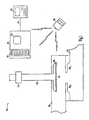
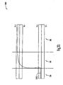
- FIG. 1 shows a system according to one aspect of the present invention.
- the system 100 includes a passageway 102 and a passageway 104. Liquid, gas, or lose material in bulk may flow through the passageway 102 and the passageway 104 to reach a desired destination. Such a flow can be started, stopped, or regulated by the valve 108.
- the valve 108 may be engaged with surfaces 106 0 and 106, to start, stop, or regulate the flow.
- the valve 108 as illustrated in Figure 1, can be considered a single-acting valve.
- a valve is typically fitted with a seat material 110.
- the seat material 110 includes rubber.
- seat material 110 may be worn away. As the seat material 110 is worn, the valve 108 settles deeper against the surfaces 106 0 and 106 1 during engagement.
- the embodiments of the present invention monitor such wear in the seat material 110 and adjust adaptively to the wear. Such adjustment will be performed until a point at which the embodiments of the present invention notify the operator to provide maintenance to the valve 108.
- the valve 108 is coupled to an actuator 112.
- the actuator 112 is a mechanical device for moving or controlling the valve 108.
- the actuator 112 may be used to engage the valve 108 with surfaces 106 0 and 106 1 .
- a magnetic source 114 is coupled to the actuator 112. As the actuator 112 moves longitudinally to control the valve 108, the magnetic source 114 radiates a magnetic field. Such a magnetic field is indicative of a position of the valve 108.
- the magnetic field may be sensed by a set of sensors 116 to derive the position of the valve 108. From the position of the valve 108, the open/closed status of the valve 108 can be inferred within a desired range.
- the desired range includes a nominal position that is used to infer the open/closed status of the valve 108.
- the desired range also includes a tolerance around the nominal position.
- the desired range may be adjusted adaptively to account for the wear of the seat material 110. In one embodiment, the desired range is adjusted within a desired limit.
- the system 100 includes a microprocessor 118.
- the microprocessor 118 executes a piece of software (not shown).
- the piece of software includes a set of counters (not shown). At least one counter of the set of counters counts each time the desired range is adjusted to characterize the valve 108 as either open or closed if the valve was not within the desired range. The count of a counter is indicative of wear in seat material 110.
- the set of counters includes a counter for an open position and a counter for a closed position.
- the piece of software also includes at least one alert level and at least one alarm level.
- the counter for an open position includes an alert level and an alarm level.
- the counter for a closed position includes an alert level and an alarm level.
- the piece of software issues an alert signal when the count of a counter reaches the alert level. In another embodiment, the piece of software issues an alarm signal when the count of a counter reaches the alarm level.
- the system 100 also includes a setup manager 120.
- the setup manager 120 may be coupled to the interface board 101 through a serial connection 121.
- the setup manager 120 manages an alteration in the alert levels and the alarm levels.
- the setup manager 120 may also selectively lock the alert levels and the alarm levels to inhibit undesired changes to the alert levels and the alarm levels.
- the setup manager 120 is a piece of software running on a personal computer.
- the piece of software includes a graphical user interface that allows the user to change various parameters and execution of the piece of software running on the microprocessor 118.
- the system 100 also includes a remote control 122.
- the remote control 122 emulates a portion of the functionality of the setup manager 120.
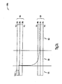
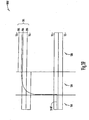
- FIG. 2 shows a system according to one aspect of the present invention.
- Figure 2 includes elements that are similar to elements discussed in Figure 1. These elements share identical last-two digits of the numerical nomenclature. Discussion of those elements presented above is incorporated here in full.
- the system 200 illustrates a valve 208 that acts as a double-acting valve.
- the valve 208 includes a seat material 210 0 and a seat material 210 1 .
- the valve 208 operates to close one passageway while contemporaneously opening another passageway.
- the valve 208 closes a passageway 205 by engaging against the surfaces 206 2 and 206 3 .
- the valve 208 is opened with respect to a passageway 204. Liquid, gas, and loose material in bulk may flow between the passageway 204 and a passageway 202.
- the embodiments of the present invention provide for additional desired ranges, counters, alert levels, and alarm levels to support the valve 208 in its operation as a double-acting valve.
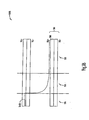
- Figures 3A, 3B, 3C, 3D, 3E, and 3F show graphs of statuses of a valve according to one aspect of the present invention.
- Figure 3A illustrates a normal open/closed sequence of a valve in operation.
- the graph 300A includes a range 301 of positions. If a position of a valve is within this range 301, the valve may be considered opened or having an open status.
- the range 301 includes a nominal position 304.
- the range 301 also includes an upper tolerance 302 and a lower tolerance 306. These tolerances describe positions that a valve may have to still be considered as having an open status.
- the graph 300A includes a range 307 of positions. If a position of a valve is within this range 307, the valve may be considered closed or having a closed status.
- the range 307 includes a nominal position 310.
- the range 307 also includes an upper tolerance 308 and a lower tolerance 312. These tolerances describe positions that a valve may have to still be considered as having a closed status.
- the graph 300A includes a waveform 314A.
- the waveform 314A illustrates an operation of the valve.
- the waveform 314A shows that the valve is initially opened at portion 316 of the graph 300A.
- the waveform 314A at portion 318 of the graph 300A shows that the valve is in a transition to a closed status. This portion 318 shows the transient behavior of the valve.
- the waveform 314A at portion 320 shows that the valve is closed.
- the waveform 314A can be considered to show a normal open/closed sequence of a valve.
- Figure 3B illustrates an abnormal open/closed sequence of a valve.
- a graph 300B includes a waveform 314B.
- the waveform 314B shows that the valve is initially opened at portion 316.
- the waveform 314B shows that the valve is in a transition from its open status at portion 316 to a closed status.
- the waveform 314B asymptotically approaches above the upper tolerance 308 of the range 307. This indicates that the valve is not fully closed. This may be caused by some obstructions, such as pulps from orange juice or such.
- the embodiments of the present invention refrain from adjusting the range 307 in such an abnormal open/closed sequence of the valve.
- Figure 3C illustrates an open/closed sequence that is adjusted adaptively by the embodiments of the present invention.
- a graph 300C includes a waveform 314C.
- the waveform 314C shows that the valve is initially opened at portion 316.
- the waveform 314C begins to approach asymptotically below the lower tolerance 312 of the range 307.
- the embodiments of the invention adjust adaptively the range 307 to characterize the valve as having a closed status even though the waveform 314C is below the original lower tolerance 312.
- the nominal position 310 is adjusted; the upper tolerance 308 and the lower tolerance 312 are automatically adjusted with the adjustment of the nominal position 310 because these tolerances are relative with respect to the nominal position 310.
- the embodiments of the present invention provide such an adjustment so as to account for the gradual wear in the seat material of the valve. As the seat material is worn, the valve may situate lower and closer to the orifice of the passageway. Thus, the adjustment allows an appropriate characterization of the open/closed status of the valve because the seat material may still function to support the desired joint, albeit worn. At a certain point, the embodiments of the present invention will continue to adjust but will also alert an operator for valve maintenance. At another point beyond that, the embodiments of the present invention will refrain from further adjustment, cease valve operations, and inform the operator.
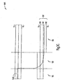
- Figure 3D illustrates a normal open/closed sequence of a valve.
- the graph 300D includes a waveform 314D.
- the waveform 314D shows that the valve is initially closed at portion 316.
- the waveform 314D at portion 318 of the graph 300D shows that the valve is in a transition to an open status.
- the waveform 314D at portion 320 shows that the valve is opened.
- the waveform 314D can be considered to show a normal open/closed sequence of a valve.
- Figure 3E illustrates an abnormal open/closed sequence of a valve.
- a graph 300E includes a waveform 314E.
- the waveform 314E shows that the valve is initially closed at portion 316.
- the waveform 314E shows that the valve is in a transition from its closed status at portion 316.
- the waveform 314E asymptotically approaches below the lower tolerance 306 of the range 301. This indicates that the valve is not fully opened. This may be caused by some mechanical failure, such as a jam.
- the embodiments of the present invention refrain from adjusting the range 301 in such an abnormal open/closed sequence of the valve.
- Figure 3F illustrates an open/closed sequence that is adjusted adaptively by the embodiments of the present invention.
- a graph 300F includes a waveform 314F.
- the waveform 314F shows that the valve is initially closed at portion 316.
- the waveform 314C begins to approach asymptotically above the upper tolerance 312 of the range 301.
- the embodiments of the invention adjust adaptively the range 301 to characterize the valve as having an open status even though the waveform 314F is above the original upper tolerance 302.
- the nominal position 304 is adjusted; the upper tolerance 302 and the lower tolerance 306 are automatically adjusted with the adjustment of the nominal position 304 because these tolerances are relative with respect to the nominal position 304.
- FIG. 4 shows a process diagram for a method according to one aspect of the present invention.
- the process 400 is a method for monitoring wear in seat materials of a valve.
- the process 400 includes an act 402 for setting a range of positions that is indicative of an open/closed status of the valve.
- the act for setting sets a range of positions.
- the range includes a nominal position and a tolerance.
- the tolerance includes an upper tolerance and a lower tolerance.
- the act for setting sets a desired range that includes a first range of positions that indicates that the valve is opened and a second range of positions that indicates that the valve is closed.
- the act for setting includes storing the range in a memory.
- the process 400 includes an act 404 for determining the open/closed status of the valve within the range of positions.
- the range is a desired range.
- the first range includes a first tolerance having an upper tolerance and a lower tolerance.
- the second range also includes an upper tolerance and a lower tolerance.
- the process 400 includes an act 406 for adjusting adaptively the range so as to characterize the valve as having the open/closed status if the valve was not within the range.
- the range is adjusted within a desired limit.
- the act for adjusting is not executed if the valve is within an undesired range.
- the undesired range includes a position that is below the lower tolerance of the first range and above the upper tolerance of the second range.
- the act for adjusting is not executed if the desired range exceeds the desired limit.
- the act for adjusting adjusts at least one of the nominal position of the first range and the nominal position of the second range.
- the process 400 includes an act for iterating the act for adjusting. Each iteration of adjusting is indicative of wear in seat materials of the valve.
- the process 400 includes other acts 408. These acts may be used alone or in combination with the others.
- One of these acts includes an act 410 for notifying if the range exceeds the desired limit.
- the act for notifying notifies an operator for valve maintenance.
- the act for notifying includes notifying an operator when the act 412 for ceasing is executed. The act for ceasing ceases valve operations if the range is within an undesired limit.
- the act for adjusting includes counting to form a count each time the act for adjusting is iterated; the act for notifying is executed when the count exceeds a desired count.
- Other acts 408 include an act 414 for controlling selectively the act for adjusting.
- the act for controlling is selected from a group consisting of enabling the act for adjusting and disabling the act for adjusting.
- the act for controlling allows an act for adjusting to execute when the open/closed status of the valve is a closed status.
- the act for controlling allows an act for adjusting to execute when the open/closed status of the valve is an open status.
- the act for controlling allows the act for adjusting to execute when the open/closed status of the valve is either a closed status or an open status.
- Other acts 408 include an act 416 for stamping the time to form a time stamp at each iteration of adjusting.
- the act for stamping further includes an act for compiling every time stamp so as to form a history of wear in seat materials of the valve. This is advantageous over current techniques because a history is produced only when desired.
- the act for stamping further includes an act for graphing every time stamp to form a graph so as to enable an analysis of wear in seat materials of the valve.
- the act for stamping further includes an act for undoing each iteration of adjusting so as to obtain back the range prior to executing the act for adjusting.
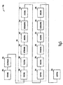
- FIG. 5 shows a process diagram for a method according to one aspect of the present invention.
- the process 500 is a method for monitoring wear in seat materials of a valve.
- the process 500 includes an act 502 for obtaining a position of the valve.
- the act for obtaining includes an act 504 for ascertaining if the position is a valid position.
- the process 500 includes an act 505 for processing the position that includes adjusting within a range.
- the act for processing includes an act 506 for verifying.
- the act 506 for verifying verifies if the position is an open position.
- the act 506 for verifying verifies if the open position is enabled so as to allow processing of the position.
- the act 506 for verifying verifies if the open position is defined.
- the act 506 for verifying verifies if the position is in an alarmed mode.
- the act for processing includes an act 508 for resetting selected variables associated with the open position.
- the act for processing includes an act 510 for determining if the position is within a desired range of the open position.
- the desired range includes a nominal open position and a tolerance.
- the act for processing includes an act 512 for adjusting the nominal open position so as to characterize the position as an open position.
- the act for processing includes an act 514 for incrementing a count that is indicative of wear in seat materials of the valve.
- the act for processing includes an act 516 for checking if the count exceeds an alert level so as to execute an act 530 for notifying.
- the act 516 for checking also checks if the count exceeds an alarm level so as to execute the act 530 for notifying.
- the act for processing includes an act 518 for verifying.
- the act 518 for verifying verifies if the position is a closed position.
- the act 518 for verifying verifies if the closed position is enabled so as to allow processing of the position.
- the act 518 for verifying verifies if the closed position is defined.
- the act 518 for verifying verifies if the position is in an alarmed mode.
- the act for processing includes an act 520 for resetting selected variables associated with the closed position.
- the act for processing includes an act 522 for determining if the position is within a desired range of the closed position.
- the desired range includes a nominal closed position and a tolerance.
- the act for processing includes an act 524 for adjusting the nominal open position so as to characterize the position as a closed position.
- the act for processing includes an act 526 for incrementing a count that is indicative of wear in seat materials of the valve.
- the act for processing includes an act 528 for checking if the count exceeds an alert level so as to execute an act 530 for notifying.
- the act 528 for checking also checks if the count exceeds an alarm level so as to execute the act 530 for notifying.
- the process 500 includes the act 530 for notifying.
- the act 530 for notifying notifies an operator the wear in seat materials of the valve.
- the act 530 for notifying may notify at two points in time. At the first point, the act 530 for notifying alerts the operator regarding the maintenance of the seat materials, but the seat materials are still functional. At the second point, the act 530 for notifying alarms the operator regarding the replacement of the seat materials because the seat materials are no longer functional.
- the act 530 for notifying may also cease valve operations at the second point.
- a maximum count (an alarm level) for adjustment can be predetermined as part of a package for a particular industry, such as dairy or nuclear energy. In one embodiment, when two-thirds of the maximum (an alert level) count is exceeded, the operator will be notified to provide valve maintenance. In another embodiment, when the maximum count is reached, valve operations will cease, and the operator will be notified.
- the range of tolerance around a nominal position that can be set is plus/minus 5 rnillimeters to zero.
- the upper tolerance can be set independently of and differently from the lower tolerance.
- the lower tolerance can be set independently of and differently from the upper tolerance.
Landscapes
- Engineering & Computer Science (AREA)
- General Engineering & Computer Science (AREA)
- Mechanical Engineering (AREA)
- Indication Of The Valve Opening Or Closing Status (AREA)
- Analysing Materials By The Use Of Radiation (AREA)
- Testing Of Devices, Machine Parts, Or Other Structures Thereof (AREA)
- Multiple-Way Valves (AREA)
- Examining Or Testing Airtightness (AREA)
Applications Claiming Priority (5)
| Application Number | Priority Date | Filing Date | Title |
|---|---|---|---|
| US14008699P | 1999-06-21 | 1999-06-21 | |
| US140086P | 1999-06-21 | ||
| US09/579,093 US6360773B1 (en) | 1999-06-21 | 2000-05-25 | Methods for monitoring wear in seat materials of valves |
| PCT/US2000/016985 WO2000079234A1 (en) | 1999-06-21 | 2000-06-21 | Methods for monitoring wear in seat materials of valves |
| US579093P | 2004-06-12 |
Publications (2)
| Publication Number | Publication Date |
|---|---|
| EP1188038A1 EP1188038A1 (en) | 2002-03-20 |
| EP1188038B1 true EP1188038B1 (en) | 2005-06-01 |
Family
ID=22489687
Family Applications (1)
| Application Number | Title | Priority Date | Filing Date |
|---|---|---|---|
| EP00941587A Expired - Lifetime EP1188038B1 (en) | 1999-06-21 | 2000-06-21 | Apparatus and method for monitoring wear in seat materials of valves |
Country Status (8)
| Country | Link |
|---|---|
| US (1) | US6360773B1 (enExample) |
| EP (1) | EP1188038B1 (enExample) |
| JP (1) | JP2004512470A (enExample) |
| AT (1) | ATE297011T1 (enExample) |
| AU (1) | AU772118B2 (enExample) |
| CA (1) | CA2375520A1 (enExample) |
| DE (1) | DE60020559T2 (enExample) |
| WO (1) | WO2000079234A1 (enExample) |
Families Citing this family (37)
| Publication number | Priority date | Publication date | Assignee | Title |
|---|---|---|---|---|
| FI114410B (fi) * | 1999-04-21 | 2004-10-15 | Larox Flowsys Oy | Letkuventtiili |
| JP4194369B2 (ja) * | 2001-05-12 | 2008-12-10 | トゥヘンハーゲン ゲーエムベーハー | バルブの切換運動を制御する方法および装置 |
| US20050222772A1 (en) * | 2003-01-29 | 2005-10-06 | Koederitz William L | Oil rig choke control systems and methods |
| US7145326B2 (en) * | 2003-12-31 | 2006-12-05 | Honeywell International Inc. | Systems and methods for position detection |
| BRPI0513016A8 (pt) * | 2004-07-05 | 2017-05-16 | Tyco Flow Control Pacific Pty Ltd | Monitoramento de estado de válvula |
| US20070034264A1 (en) * | 2005-08-12 | 2007-02-15 | Stonel Corporation | Apparatus for valve communication and control |
| US7469604B2 (en) * | 2005-10-21 | 2008-12-30 | Stoneridge Control Devices, Inc. | Sensor system including a magnetized shaft |
| JP4483770B2 (ja) * | 2005-11-18 | 2010-06-16 | 株式会社デンソー | 電磁弁異常診断方法 |
| US9846440B2 (en) | 2011-12-15 | 2017-12-19 | Honeywell International Inc. | Valve controller configured to estimate fuel comsumption |
| US8905063B2 (en) | 2011-12-15 | 2014-12-09 | Honeywell International Inc. | Gas valve with fuel rate monitor |
| US8839815B2 (en) * | 2011-12-15 | 2014-09-23 | Honeywell International Inc. | Gas valve with electronic cycle counter |
| US9995486B2 (en) | 2011-12-15 | 2018-06-12 | Honeywell International Inc. | Gas valve with high/low gas pressure detection |
| US9835265B2 (en) | 2011-12-15 | 2017-12-05 | Honeywell International Inc. | Valve with actuator diagnostics |
| US8947242B2 (en) | 2011-12-15 | 2015-02-03 | Honeywell International Inc. | Gas valve with valve leakage test |
| US9074770B2 (en) | 2011-12-15 | 2015-07-07 | Honeywell International Inc. | Gas valve with electronic valve proving system |
| US8899264B2 (en) * | 2011-12-15 | 2014-12-02 | Honeywell International Inc. | Gas valve with electronic proof of closure system |
| US9851103B2 (en) | 2011-12-15 | 2017-12-26 | Honeywell International Inc. | Gas valve with overpressure diagnostics |
| US9557059B2 (en) | 2011-12-15 | 2017-01-31 | Honeywell International Inc | Gas valve with communication link |
| JP6105868B2 (ja) * | 2012-06-26 | 2017-03-29 | 株式会社不二工機 | 電動弁制御装置及び電動弁装置 |
| US10422531B2 (en) | 2012-09-15 | 2019-09-24 | Honeywell International Inc. | System and approach for controlling a combustion chamber |
| US9234661B2 (en) | 2012-09-15 | 2016-01-12 | Honeywell International Inc. | Burner control system |
| WO2014106096A1 (en) * | 2012-12-27 | 2014-07-03 | Kaleo, Inc. | Devices, systems and methods for locating and interacting with medicament delivery systems |
| US9309992B2 (en) * | 2013-03-15 | 2016-04-12 | Sdb Ip Holdings, Llc | System for detecting that a valve should be replaced and a method of use thereof |
| EP2868970B1 (en) | 2013-10-29 | 2020-04-22 | Honeywell Technologies Sarl | Regulating device |
| US10024439B2 (en) | 2013-12-16 | 2018-07-17 | Honeywell International Inc. | Valve over-travel mechanism |
| US9841122B2 (en) | 2014-09-09 | 2017-12-12 | Honeywell International Inc. | Gas valve with electronic valve proving system |
| US9645584B2 (en) | 2014-09-17 | 2017-05-09 | Honeywell International Inc. | Gas valve with electronic health monitoring |
| US10503181B2 (en) | 2016-01-13 | 2019-12-10 | Honeywell International Inc. | Pressure regulator |
| US10564062B2 (en) | 2016-10-19 | 2020-02-18 | Honeywell International Inc. | Human-machine interface for gas valve |
| WO2019003185A1 (en) * | 2017-06-29 | 2019-01-03 | Eaton Intelligent Power Limited | SYSTEM AND METHOD FOR VALVE DIAGNOSIS |
| HUE052767T2 (hu) | 2017-07-17 | 2021-05-28 | Siemens Ag | Kopás meghatározása szelepeknél |
| US11073281B2 (en) | 2017-12-29 | 2021-07-27 | Honeywell International Inc. | Closed-loop programming and control of a combustion appliance |
| US10697815B2 (en) | 2018-06-09 | 2020-06-30 | Honeywell International Inc. | System and methods for mitigating condensation in a sensor module |
| DE102018114710B4 (de) | 2018-06-19 | 2020-07-16 | Samson Aktiengesellschaft | Erkennen mangelhafter Sitz-Integrität bei einem Stellventil |
| DE102018116048B4 (de) * | 2018-07-03 | 2020-10-01 | Samson Aktiengesellschaft | Diagnose von möglichen Ursachen für Veränderungen an einem Stellventil |
| US10968823B1 (en) * | 2019-10-25 | 2021-04-06 | Caterpillar Inc. | Method and system for wear estimation |
| DE102019129368B4 (de) * | 2019-10-30 | 2025-01-30 | Samson Aktiengesellschaft | Festlegen von Abbruchkriterien für einen Teilhubtest an einem fluidisch angetriebenen Sicherheitsventil sowie Bestimmen der Funktionsfähigkeit eines fluidisch angetriebenen Sicherheitsventils |
Family Cites Families (17)
| Publication number | Priority date | Publication date | Assignee | Title |
|---|---|---|---|---|
| DE2314954C3 (de) * | 1973-03-26 | 1982-08-26 | Brown, Boveri & Cie Ag, 6800 Mannheim | Anordnung zur laufenden Ermittlung und Überwachung der Lebensdauer von thermisch belasteten dickwandigen Bauelementen |
| US4129037A (en) * | 1977-03-21 | 1978-12-12 | Toalson David C | Apparatus for wear detection |
| US4481805A (en) | 1981-06-03 | 1984-11-13 | F. H. Maloney Company | Meter prover apparatus and method |
| US4461316A (en) * | 1982-09-02 | 1984-07-24 | Hydril Company | Drilling choke |
| US4505243A (en) | 1983-07-04 | 1985-03-19 | Nissan Motor Company, Limited | Electromagnetic injection control valve in unit fuel injector |
| DE3442750A1 (de) | 1984-11-23 | 1986-05-28 | Robert Bosch Gmbh, 7000 Stuttgart | Magnetventil zur fluidsteuerung |
| US5154080A (en) * | 1986-10-29 | 1992-10-13 | Westinghouse Electric Corp. | Integrated check valve testing system |
| US4735229A (en) * | 1987-05-01 | 1988-04-05 | Varco/Best Flow Products | Wear monitoring construction for erosive/corrosive flow conducting devices |
| KR890007306A (ko) * | 1987-10-30 | 1989-06-19 | 제트.엘.더머 | 온라인 밸브 진단 감시 시스템 |
| US4874007A (en) * | 1989-01-12 | 1989-10-17 | Taylor Julian S | Restrictor valve flow passage pop-up wear indicator |
| DE3936619A1 (de) | 1989-11-03 | 1991-05-08 | Man Nutzfahrzeuge Ag | Verfahren zum einspritzen eines brennstoffes in einen brennraum einer luftverdichtenden, selbstzuendenden brennkraftmaschine, sowie vorrichtungen zur durchfuehrung dieses verfahrens |
| US5086273A (en) * | 1990-04-20 | 1992-02-04 | Liberty Technology Center, Inc. | A.C. electromagnetic system for determining position of an encased movable electrically conductive element |
| DK142593D0 (da) * | 1993-12-21 | 1993-12-21 | Ole Cramer Nielsen | Apparat til styring af en ventil |
| US5524484A (en) * | 1993-12-22 | 1996-06-11 | Westinghouse Electric Corporation | Solenoid operated valve diagnostic system |
| DE19547374A1 (de) | 1995-12-19 | 1997-06-26 | Bosch Gmbh Robert | Elektrisch steuerbares Ventil insbesondere zum Einbau in eine hydraulische Fahrzeugbremsanlage |
| JP3907079B2 (ja) * | 1997-01-10 | 2007-04-18 | 本田技研工業株式会社 | ポンプ装置のリーク検出方法及び装置 |
| SE9800229D0 (sv) | 1998-01-28 | 1998-01-28 | Siemens Elema Ab | Fluid pressure release valve |
-
2000
- 2000-05-25 US US09/579,093 patent/US6360773B1/en not_active Expired - Fee Related
- 2000-06-21 CA CA 2375520 patent/CA2375520A1/en not_active Abandoned
- 2000-06-21 WO PCT/US2000/016985 patent/WO2000079234A1/en not_active Ceased
- 2000-06-21 EP EP00941587A patent/EP1188038B1/en not_active Expired - Lifetime
- 2000-06-21 AT AT00941587T patent/ATE297011T1/de not_active IP Right Cessation
- 2000-06-21 AU AU56278/00A patent/AU772118B2/en not_active Ceased
- 2000-06-21 JP JP2001505155A patent/JP2004512470A/ja active Pending
- 2000-06-21 DE DE2000620559 patent/DE60020559T2/de not_active Expired - Fee Related
Also Published As
| Publication number | Publication date |
|---|---|
| US6360773B1 (en) | 2002-03-26 |
| ATE297011T1 (de) | 2005-06-15 |
| JP2004512470A (ja) | 2004-04-22 |
| AU772118B2 (en) | 2004-04-08 |
| AU5627800A (en) | 2001-01-09 |
| DE60020559T2 (de) | 2006-03-23 |
| EP1188038A1 (en) | 2002-03-20 |
| DE60020559D1 (de) | 2005-07-07 |
| WO2000079234A1 (en) | 2000-12-28 |
| CA2375520A1 (en) | 2000-12-28 |
Similar Documents
| Publication | Publication Date | Title |
|---|---|---|
| EP1188038B1 (en) | Apparatus and method for monitoring wear in seat materials of valves | |
| CA2656180C (en) | Computerized evaluation of process control device signature graphs | |
| DE69833893T2 (de) | Ventilstellungsregelsystem | |
| US7130703B2 (en) | Voter logic block including operational and maintenance overrides in a process control system | |
| US8744604B2 (en) | Method and apparatus for configuring a blackout period for scheduled diagnostic checks of a field device in a process plant | |
| US8265779B2 (en) | Automatic backlash estimation | |
| CN104216433A (zh) | 在智能调节器组件中用于稳定压力的方法及装置 | |
| US11294366B2 (en) | Monitoring system, monitoring method and monitoring program for steam-using facility | |
| WO2019002488A1 (de) | Vakuumventil mit akustischem sensor | |
| CN100402907C (zh) | 监测管道横截面的方法及实施此方法的调节阀位置调节器 | |
| JP6071534B2 (ja) | 安全計装システムおよびpst起動方法 | |
| JP2004310767A (ja) | オーバライドおよびバイパスを利用したプロセス制御・安全システム内におけるフィールドデバイスの動作調整 | |
| CN117806289A (zh) | 一种闸阀定位控制系统及方法 | |
| JP6174911B2 (ja) | ガス遮断装置 | |
| JP4843537B2 (ja) | 空調制御システムにおける中央監視制御方法および装置 | |
| JP6670167B2 (ja) | 油圧式作業機械の蓄圧装置 | |
| EP2749970A1 (en) | Safety instrument system and method for permitting PST | |
| JPH1030603A (ja) | 電空ポジショナ | |
| Xue et al. | Research on design method of safety components in grader control system | |
| JP2002323402A (ja) | バルブの漏れ検出装置,方法,バルブ駆動用アクチュエータ,プログラム | |
| CN120836281A (zh) | 联合收获机堵塞检测方法、系统、电子设备和存储介质 | |
| JP2020016320A (ja) | ポジショナの動作モード判定装置および方法 | |
| DE10224864A1 (de) | Sensorüberwachungseinrichtung und -verfahren |
Legal Events
| Date | Code | Title | Description |
|---|---|---|---|
| PUAI | Public reference made under article 153(3) epc to a published international application that has entered the european phase |
Free format text: ORIGINAL CODE: 0009012 |
|
| 17P | Request for examination filed |
Effective date: 20011212 |
|
| AK | Designated contracting states |
Kind code of ref document: A1 Designated state(s): AT BE CH CY DE DK ES FI FR GB GR IE IT LI LU MC NL PT SE |
|
| AX | Request for extension of the european patent |
Free format text: AL;LT;LV;MK;RO;SI |
|
| 17Q | First examination report despatched |
Effective date: 20031126 |
|
| GRAP | Despatch of communication of intention to grant a patent |
Free format text: ORIGINAL CODE: EPIDOSNIGR1 |
|
| RTI1 | Title (correction) |
Free format text: APPARATUS AND METHOD FOR MONITORING WEAR IN SEAT MATERIALS OF VALVES |
|
| GRAS | Grant fee paid |
Free format text: ORIGINAL CODE: EPIDOSNIGR3 |
|
| GRAA | (expected) grant |
Free format text: ORIGINAL CODE: 0009210 |
|
| AK | Designated contracting states |
Kind code of ref document: B1 Designated state(s): AT BE CH CY DE DK ES FI FR GB GR IE IT LI LU MC NL PT SE |
|
| PG25 | Lapsed in a contracting state [announced via postgrant information from national office to epo] |
Ref country code: IT Free format text: LAPSE BECAUSE OF FAILURE TO SUBMIT A TRANSLATION OF THE DESCRIPTION OR TO PAY THE FEE WITHIN THE PRESCRIBED TIME-LIMIT;WARNING: LAPSES OF ITALIAN PATENTS WITH EFFECTIVE DATE BEFORE 2007 MAY HAVE OCCURRED AT ANY TIME BEFORE 2007. THE CORRECT EFFECTIVE DATE MAY BE DIFFERENT FROM THE ONE RECORDED. Effective date: 20050601 Ref country code: CH Free format text: LAPSE BECAUSE OF FAILURE TO SUBMIT A TRANSLATION OF THE DESCRIPTION OR TO PAY THE FEE WITHIN THE PRESCRIBED TIME-LIMIT Effective date: 20050601 Ref country code: BE Free format text: LAPSE BECAUSE OF FAILURE TO SUBMIT A TRANSLATION OF THE DESCRIPTION OR TO PAY THE FEE WITHIN THE PRESCRIBED TIME-LIMIT Effective date: 20050601 Ref country code: LI Free format text: LAPSE BECAUSE OF FAILURE TO SUBMIT A TRANSLATION OF THE DESCRIPTION OR TO PAY THE FEE WITHIN THE PRESCRIBED TIME-LIMIT Effective date: 20050601 Ref country code: NL Free format text: LAPSE BECAUSE OF FAILURE TO SUBMIT A TRANSLATION OF THE DESCRIPTION OR TO PAY THE FEE WITHIN THE PRESCRIBED TIME-LIMIT Effective date: 20050601 Ref country code: FI Free format text: LAPSE BECAUSE OF FAILURE TO SUBMIT A TRANSLATION OF THE DESCRIPTION OR TO PAY THE FEE WITHIN THE PRESCRIBED TIME-LIMIT Effective date: 20050601 Ref country code: AT Free format text: LAPSE BECAUSE OF FAILURE TO SUBMIT A TRANSLATION OF THE DESCRIPTION OR TO PAY THE FEE WITHIN THE PRESCRIBED TIME-LIMIT Effective date: 20050601 |
|
| REG | Reference to a national code |
Ref country code: GB Ref legal event code: FG4D |
|
| REG | Reference to a national code |
Ref country code: CH Ref legal event code: EP |
|
| PG25 | Lapsed in a contracting state [announced via postgrant information from national office to epo] |
Ref country code: IE Free format text: LAPSE BECAUSE OF NON-PAYMENT OF DUE FEES Effective date: 20050621 Ref country code: CY Free format text: LAPSE BECAUSE OF FAILURE TO SUBMIT A TRANSLATION OF THE DESCRIPTION OR TO PAY THE FEE WITHIN THE PRESCRIBED TIME-LIMIT Effective date: 20050621 Ref country code: LU Free format text: LAPSE BECAUSE OF NON-PAYMENT OF DUE FEES Effective date: 20050621 |
|
| PG25 | Lapsed in a contracting state [announced via postgrant information from national office to epo] |
Ref country code: MC Free format text: LAPSE BECAUSE OF NON-PAYMENT OF DUE FEES Effective date: 20050630 |
|
| REF | Corresponds to: |
Ref document number: 60020559 Country of ref document: DE Date of ref document: 20050707 Kind code of ref document: P |
|
| REG | Reference to a national code |
Ref country code: IE Ref legal event code: FG4D |
|
| PG25 | Lapsed in a contracting state [announced via postgrant information from national office to epo] |
Ref country code: SE Free format text: LAPSE BECAUSE OF FAILURE TO SUBMIT A TRANSLATION OF THE DESCRIPTION OR TO PAY THE FEE WITHIN THE PRESCRIBED TIME-LIMIT Effective date: 20050901 Ref country code: DK Free format text: LAPSE BECAUSE OF FAILURE TO SUBMIT A TRANSLATION OF THE DESCRIPTION OR TO PAY THE FEE WITHIN THE PRESCRIBED TIME-LIMIT Effective date: 20050901 Ref country code: GR Free format text: LAPSE BECAUSE OF FAILURE TO SUBMIT A TRANSLATION OF THE DESCRIPTION OR TO PAY THE FEE WITHIN THE PRESCRIBED TIME-LIMIT Effective date: 20050901 |
|
| PG25 | Lapsed in a contracting state [announced via postgrant information from national office to epo] |
Ref country code: ES Free format text: LAPSE BECAUSE OF FAILURE TO SUBMIT A TRANSLATION OF THE DESCRIPTION OR TO PAY THE FEE WITHIN THE PRESCRIBED TIME-LIMIT Effective date: 20050912 |
|
| PG25 | Lapsed in a contracting state [announced via postgrant information from national office to epo] |
Ref country code: PT Free format text: LAPSE BECAUSE OF FAILURE TO SUBMIT A TRANSLATION OF THE DESCRIPTION OR TO PAY THE FEE WITHIN THE PRESCRIBED TIME-LIMIT Effective date: 20051107 |
|
| NLV1 | Nl: lapsed or annulled due to failure to fulfill the requirements of art. 29p and 29m of the patents act | ||
| REG | Reference to a national code |
Ref country code: CH Ref legal event code: PL |
|
| REG | Reference to a national code |
Ref country code: IE Ref legal event code: MM4A |
|
| ET | Fr: translation filed | ||
| PLBE | No opposition filed within time limit |
Free format text: ORIGINAL CODE: 0009261 |
|
| STAA | Information on the status of an ep patent application or granted ep patent |
Free format text: STATUS: NO OPPOSITION FILED WITHIN TIME LIMIT |
|
| 26N | No opposition filed |
Effective date: 20060302 |
|
| PGFP | Annual fee paid to national office [announced via postgrant information from national office to epo] |
Ref country code: FR Payment date: 20090605 Year of fee payment: 10 |
|
| PGFP | Annual fee paid to national office [announced via postgrant information from national office to epo] |
Ref country code: DE Payment date: 20090630 Year of fee payment: 10 |
|
| PGFP | Annual fee paid to national office [announced via postgrant information from national office to epo] |
Ref country code: GB Payment date: 20100401 Year of fee payment: 11 |
|
| REG | Reference to a national code |
Ref country code: FR Ref legal event code: ST Effective date: 20110228 |
|
| PG25 | Lapsed in a contracting state [announced via postgrant information from national office to epo] |
Ref country code: DE Free format text: LAPSE BECAUSE OF NON-PAYMENT OF DUE FEES Effective date: 20110101 |
|
| PG25 | Lapsed in a contracting state [announced via postgrant information from national office to epo] |
Ref country code: FR Free format text: LAPSE BECAUSE OF NON-PAYMENT OF DUE FEES Effective date: 20100630 |
|
| GBPC | Gb: european patent ceased through non-payment of renewal fee |
Effective date: 20110621 |
|
| PG25 | Lapsed in a contracting state [announced via postgrant information from national office to epo] |
Ref country code: GB Free format text: LAPSE BECAUSE OF NON-PAYMENT OF DUE FEES Effective date: 20110621 |