EP1187975B1 - Verfahren und vorrichtung zur desulfatisierung eines stickoxidabsorbers - Google Patents
Verfahren und vorrichtung zur desulfatisierung eines stickoxidabsorbers Download PDFInfo
- Publication number
- EP1187975B1 EP1187975B1 EP00934991A EP00934991A EP1187975B1 EP 1187975 B1 EP1187975 B1 EP 1187975B1 EP 00934991 A EP00934991 A EP 00934991A EP 00934991 A EP00934991 A EP 00934991A EP 1187975 B1 EP1187975 B1 EP 1187975B1
- Authority
- EP
- European Patent Office
- Prior art keywords
- exhaust gas
- desulphurisation
- nitrogen oxide
- value
- carbon monoxide
- Prior art date
- Legal status (The legal status is an assumption and is not a legal conclusion. Google has not performed a legal analysis and makes no representation as to the accuracy of the status listed.)
- Expired - Lifetime
Links
- MWUXSHHQAYIFBG-UHFFFAOYSA-N Nitric oxide Chemical compound O=[N] MWUXSHHQAYIFBG-UHFFFAOYSA-N 0.000 title claims description 134
- 238000000034 method Methods 0.000 title claims description 9
- 239000007789 gas Substances 0.000 claims description 41
- UGFAIRIUMAVXCW-UHFFFAOYSA-N Carbon monoxide Chemical compound [O+]#[C-] UGFAIRIUMAVXCW-UHFFFAOYSA-N 0.000 claims description 31
- 229910002091 carbon monoxide Inorganic materials 0.000 claims description 31
- 238000002485 combustion reaction Methods 0.000 claims description 26
- 239000000203 mixture Substances 0.000 claims description 13
- 239000000523 sample Substances 0.000 claims description 8
- 238000000746 purification Methods 0.000 claims description 3
- 238000006477 desulfuration reaction Methods 0.000 description 25
- 230000023556 desulfurization Effects 0.000 description 25
- RAHZWNYVWXNFOC-UHFFFAOYSA-N Sulphur dioxide Chemical compound O=S=O RAHZWNYVWXNFOC-UHFFFAOYSA-N 0.000 description 22
- RWSOTUBLDIXVET-UHFFFAOYSA-N Dihydrogen sulfide Chemical compound S RWSOTUBLDIXVET-UHFFFAOYSA-N 0.000 description 19
- 229910000037 hydrogen sulfide Inorganic materials 0.000 description 17
- 239000003054 catalyst Substances 0.000 description 13
- NINIDFKCEFEMDL-UHFFFAOYSA-N Sulfur Chemical compound [S] NINIDFKCEFEMDL-UHFFFAOYSA-N 0.000 description 10
- 238000003795 desorption Methods 0.000 description 10
- 229910052717 sulfur Inorganic materials 0.000 description 10
- 239000011593 sulfur Substances 0.000 description 10
- 238000001179 sorption measurement Methods 0.000 description 9
- 239000000446 fuel Substances 0.000 description 8
- 230000015572 biosynthetic process Effects 0.000 description 5
- 238000012360 testing method Methods 0.000 description 5
- IJGRMHOSHXDMSA-UHFFFAOYSA-N Atomic nitrogen Chemical compound N#N IJGRMHOSHXDMSA-UHFFFAOYSA-N 0.000 description 4
- 230000007423 decrease Effects 0.000 description 4
- 230000008929 regeneration Effects 0.000 description 4
- 238000011069 regeneration method Methods 0.000 description 4
- QAOWNCQODCNURD-UHFFFAOYSA-L Sulfate Chemical compound [O-]S([O-])(=O)=O QAOWNCQODCNURD-UHFFFAOYSA-L 0.000 description 3
- QVGXLLKOCUKJST-UHFFFAOYSA-N atomic oxygen Chemical compound [O] QVGXLLKOCUKJST-UHFFFAOYSA-N 0.000 description 3
- 238000011835 investigation Methods 0.000 description 3
- 239000001301 oxygen Substances 0.000 description 3
- 229910052760 oxygen Inorganic materials 0.000 description 3
- QGZKDVFQNNGYKY-UHFFFAOYSA-N Ammonia Chemical compound N QGZKDVFQNNGYKY-UHFFFAOYSA-N 0.000 description 2
- JJWKPURADFRFRB-UHFFFAOYSA-N carbonyl sulfide Chemical compound O=C=S JJWKPURADFRFRB-UHFFFAOYSA-N 0.000 description 2
- 238000010586 diagram Methods 0.000 description 2
- 238000011156 evaluation Methods 0.000 description 2
- NHNBFGGVMKEFGY-UHFFFAOYSA-N nitrate group Chemical group [N+](=O)([O-])[O-] NHNBFGGVMKEFGY-UHFFFAOYSA-N 0.000 description 2
- 229910052757 nitrogen Inorganic materials 0.000 description 2
- 231100000572 poisoning Toxicity 0.000 description 2
- 230000000607 poisoning effect Effects 0.000 description 2
- UFHFLCQGNIYNRP-UHFFFAOYSA-N Hydrogen Chemical compound [H][H] UFHFLCQGNIYNRP-UHFFFAOYSA-N 0.000 description 1
- 229910002651 NO3 Inorganic materials 0.000 description 1
- 229910021529 ammonia Inorganic materials 0.000 description 1
- 238000013459 approach Methods 0.000 description 1
- 238000010531 catalytic reduction reaction Methods 0.000 description 1
- 238000006243 chemical reaction Methods 0.000 description 1
- 239000003638 chemical reducing agent Substances 0.000 description 1
- 238000004140 cleaning Methods 0.000 description 1
- 239000000470 constituent Substances 0.000 description 1
- 230000002950 deficient Effects 0.000 description 1
- 230000001934 delay Effects 0.000 description 1
- 230000003111 delayed effect Effects 0.000 description 1
- 230000001419 dependent effect Effects 0.000 description 1
- 238000001514 detection method Methods 0.000 description 1
- 238000011161 development Methods 0.000 description 1
- 230000018109 developmental process Effects 0.000 description 1
- 230000002349 favourable effect Effects 0.000 description 1
- 239000004519 grease Substances 0.000 description 1
- 229930195733 hydrocarbon Natural products 0.000 description 1
- 150000002430 hydrocarbons Chemical class 0.000 description 1
- 239000001257 hydrogen Substances 0.000 description 1
- 229910052739 hydrogen Inorganic materials 0.000 description 1
- 238000011068 loading method Methods 0.000 description 1
- 239000000463 material Substances 0.000 description 1
- 239000010705 motor oil Substances 0.000 description 1
- -1 nitrite form Nitrogen oxides Chemical class 0.000 description 1
- 238000006722 reduction reaction Methods 0.000 description 1
- 238000011160 research Methods 0.000 description 1
- 150000003464 sulfur compounds Chemical class 0.000 description 1
- XTQHKBHJIVJGKJ-UHFFFAOYSA-N sulfur monoxide Chemical class S=O XTQHKBHJIVJGKJ-UHFFFAOYSA-N 0.000 description 1
- 229910052815 sulfur oxide Inorganic materials 0.000 description 1
- 150000003467 sulfuric acid derivatives Chemical class 0.000 description 1
- 238000005987 sulfurization reaction Methods 0.000 description 1
- 230000009466 transformation Effects 0.000 description 1
- 238000000844 transformation Methods 0.000 description 1
- 239000002699 waste material Substances 0.000 description 1
Images

Classifications
-
- B—PERFORMING OPERATIONS; TRANSPORTING
- B01—PHYSICAL OR CHEMICAL PROCESSES OR APPARATUS IN GENERAL
- B01D—SEPARATION
- B01D53/00—Separation of gases or vapours; Recovering vapours of volatile solvents from gases; Chemical or biological purification of waste gases, e.g. engine exhaust gases, smoke, fumes, flue gases, aerosols
- B01D53/34—Chemical or biological purification of waste gases
- B01D53/92—Chemical or biological purification of waste gases of engine exhaust gases
- B01D53/94—Chemical or biological purification of waste gases of engine exhaust gases by catalytic processes
- B01D53/9495—Controlling the catalytic process
-
- B—PERFORMING OPERATIONS; TRANSPORTING
- B01—PHYSICAL OR CHEMICAL PROCESSES OR APPARATUS IN GENERAL
- B01D—SEPARATION
- B01D53/00—Separation of gases or vapours; Recovering vapours of volatile solvents from gases; Chemical or biological purification of waste gases, e.g. engine exhaust gases, smoke, fumes, flue gases, aerosols
- B01D53/34—Chemical or biological purification of waste gases
- B01D53/92—Chemical or biological purification of waste gases of engine exhaust gases
- B01D53/94—Chemical or biological purification of waste gases of engine exhaust gases by catalytic processes
- B01D53/9404—Removing only nitrogen compounds
- B01D53/9409—Nitrogen oxides
-
- B—PERFORMING OPERATIONS; TRANSPORTING
- B01—PHYSICAL OR CHEMICAL PROCESSES OR APPARATUS IN GENERAL
- B01D—SEPARATION
- B01D53/00—Separation of gases or vapours; Recovering vapours of volatile solvents from gases; Chemical or biological purification of waste gases, e.g. engine exhaust gases, smoke, fumes, flue gases, aerosols
- B01D53/34—Chemical or biological purification of waste gases
- B01D53/96—Regeneration, reactivation or recycling of reactants
Definitions
- the invention relates to a method and a device for the desulfation of a nitrogen oxide adsorber Emission control system for a combustion device by means of desulfurization phases carried out from time to time.
- a known difficulty of such systems is that due to sulfur, which is contained in conventional fuels and engine oils, sulfur dioxide in the exhaust gas is present, which can lead by sulfurization to sulfur poisoning of the Stickstoffoxidadsorbers that reduces its nitrogen oxide storage capacity over time. It is therefore known that the nitrogen oxide adsorber whenever it decreases significantly in its nitrogen oxide storage capacity to undergo a Desulfatticiansvorgang to free him from the accumulated sulfate.
- nitrogen oxide adsorber in the present case should include both the case that consists of a single adsorber, as well as the equally known case that the actual nitric oxide adsorber body is preceded by a so-called SO x trap, which caches the sulfur oxides and so from the nitrogen oxide Keeps adsorber body away and is subjected in an analogous manner from time to time desulfation.
- SO x trap caches the sulfur oxides and so from the nitrogen oxide Keeps adsorber body away and is subjected in an analogous manner from time to time desulfation.
- the invention is the provision as a technical problem a method and a device of the beginning based on this type, with which the nitrogen oxide adsorber effectively desulfate and in which measures for the lowest possible emission of hydrogen sulphide are met.
- the invention solves this problem by providing a Desulfatmaschinesvons with the features of the claim 1 and one suitable for its implementation Desulfating device with the features of the claim Second
- this finding is used to detect the occurrence of its local maximum or, by detecting the lambda value, the occurrence of its falling step edge during the desulfurization phase by detecting the CO content and to use this as a criterion for terminating the desorption phase.
- the Emission control system includes a in the exhaust line 3 of Incinerator 1 lying catalytically effective Nitric oxide adsorber, i. a nitrogen oxide adsorber catalyst 4th
- the general desire for minimum fuel consumption Accordingly, the combustion device 1 as possible much in lean operation, as far as the operating situation allows.
- the lean operation usually results in an increased nitrogen oxide content in the exhaust gas of the combustion device 1.
- the adsorber catalyst 4 serves to during these operating phases in the adsorption mode the Remove nitrogen oxides by adsorption from the exhaust stream. Once its nitrogen oxide capacity is exhausted, is switched to desorption. In the desorption phase the adsorber 4 is regenerated by the previously stored primarily in nitrate or nitrite form Nitrogen oxides are desorbed and converted again.
- Nitrogen oxides also contained in the exhaust gas sulfur in the Adsorber catalyst 4 stored mainly in sulfate form.
- the sulfur storage is compared to the usual Nitrogen oxide desorption conditions are quite resistant, so that the sulfur stored in the adsorption mode during the Nitrogen desorption operation is not completely released becomes. Since the embedded sulfur, the nitrogen oxide adsorption the adsorber 4 blocked, occurs with the time a sulfur poisoning of the same up, the to causes its nitrogen oxide storage capacity to decrease. If the nitrogen oxide storage capacity below a certain value is therefore a desulfating process carried out in which the adsorber 4 via a Duration, which is typically much longer than that of a respective nitrogen oxide desorption phase, suitable Desulfatmaschines committee is subjected.
- a suitable desulfating temperature e.g. 600 ° C or above. This will be the accumulated the catalyst material of the adsorber 4 Sulfates are unstable and can be desorbed.
- FIGS. 2 and 3 diagrammatically show the result of an experimental test operation of the system of FIG. 1 for examining the time course of the concentration of various exhaust components in the exhaust gas downstream of the adsorber catalyst 4, especially during a desulfurization phase.
- Fig. 2 are over a period of 110min with a temperature characteristic T the exhaust gas temperature, with, a sulfur dioxide curve SO2 the sulfur dioxide content of the exhaust stream, with a characteristic H2S the hydrogen sulfide content of the exhaust stream and with a characteristic COS of the COS (carbonoxisulfide) content of Exhaust gas stream, reproduced in each case over time, detected by corresponding sensors in the exhaust line 3 downstream of the adsorber 4 during the test phase of operation.
- T the exhaust gas temperature
- SO2 sulfur dioxide
- H2S hydrogen sulfide content of the exhaust stream
- COS carbonoxisulfide
- the CO concentration increases in the exhaust gas downstream of the adsorber 4 after the start of desulfation first for about 1min only slowly and then within 0.5 minutes steeply until at a time of about t 87 minutes after the start of the test operation, ie approximately at the time of maximum release of SO 2, assumes a local maximum M, from which it first slowly drops again, before it then begins to increase again later.
- this local maximum in the CO * 2 characteristic of the carbon monoxide content always occurs before the onset of appreciable hydrogen sulfide formation at a time when significant amounts of sulfur have already been desorbed in the adsorber catalyst 4 and emitted as sulfur dioxide.
- this finding is exploited to use the occurrence of the local maximum M of the CO concentration in the exhaust gas downstream of the adsorber catalyst 4 during a desulfurization phase as a criterion for a timely termination thereof, before hydrogen sulfide noticeably develops.
- the desulfating phase can be carried out immediately after detection of the local maximum M of the CO concentration or, conversely, delayed by a defined, predetermined period of time.
- the delay period can be determined experimentally, for example, and made dependent on how much H 2 S emissions are to be tolerated. Attention is paid to the greatest possible desulfurization of the adsorber 4, since investigations indicate that too short Desulfatmaschinesphasen with only partial sulfate regeneration, even with repeated successive applications do not appear to lead to a full regeneration of the adsorber 4.
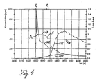
- FIG. 4 shows, in a manner similar to FIG. 3, but with a higher time resolution, a curve diagram for a further embodiment according to the invention, in which instead of the CO sensor 5 in the system of FIG. 1 a conventional lambda probe is used which determines the lambda value of the nitrogen oxide adsorber 4 leaving exhaust gas flow detected and the Desulfatticians Kunststofftechnik 2 reports.
- a desulfurization process is switched over, again by the lambda ratio of the mixture supplied to the combustion device 1 being changed to a rich value, by way of example to a value of approx. 0.9.
- the occurrence of this falling step edge F of the exhaust lambda value ⁇ coincides in a timely manner with an incipient marked increase in H 2 S release, as occurs with the characteristic curve H 2 S of the hydrogen sulfide content in the exhaust gas downstream of the adsorber catalyst 4 Fig. 4 is illustrated.
- both a CO sensor and a lambda sensor are then arranged in the exhaust gas line 3 downstream of the adsorber catalyst 4, and the desulfating control unit 2 appropriately evaluates the output signals of both sensors.
- This can be done depending on the application, a termination of Desulfatmaschinesphase already at the occurrence of the first of the two criteria or only when the occurrence of the second criterion, each with or without time delay.
- there is in this case a reliability-increasing redundancy which also allows a timely termination of desulfation before noticeable H 2 S release when either the CO sensor or the lambda probe is defective.
- the invention provides a simple possibility for determining a favorable switch-off time for the desulfurization phases, which enables a change from desulfurization operation to subsequent normal operation with lean exhaust gas composition even before the development of significant amounts of hydrogen sulfide, if necessary.
- the invention does not require a hydrogen sulfide sensor, but only a conventional carbon monoxide sensor 5 and / or a conventional lambda probe in the exhaust line 3 downstream of the adsorber catalyst 4, as shown in Fig. 1. This is, as also illustrated in Fig.
- the desulfurization control unit 2 is preferably formed by an engine control unit which, moreover, controls the motor vehicle internal combustion engine 1 in a conventional manner.
- the desulfurization control unit 2 switches the combustion device 1 from lean to rich operation as needed to initiate a desulfurization phase, and then observes the time course of the carbon monoxide concentration or the lambda sensor based on the output signal of the CO sensor 5 As soon as the desulfurization control unit 2 recognizes that the detected carbon monoxide concentration has reached its local maximum M and / or the detected lambda value curve has fallen from the temporary plateau value ⁇ p from falling edge F, it ends immediately or by one predetermined period delays the Desulfatticiansphase by switching the operation of the combustion device 1 back to lean operation.
Landscapes
- Chemical & Material Sciences (AREA)
- Engineering & Computer Science (AREA)
- Analytical Chemistry (AREA)
- Health & Medical Sciences (AREA)
- Biomedical Technology (AREA)
- Environmental & Geological Engineering (AREA)
- General Chemical & Material Sciences (AREA)
- Oil, Petroleum & Natural Gas (AREA)
- Chemical Kinetics & Catalysis (AREA)
- Combustion & Propulsion (AREA)
- Life Sciences & Earth Sciences (AREA)
- Sustainable Development (AREA)
- Exhaust Gas After Treatment (AREA)
- Exhaust Gas Treatment By Means Of Catalyst (AREA)
Description
- Fig. 1
- ein schematisches Blockdiagramm einer Verbrennungseinrichtung mit zugeordneter Abgasreinigungsanlage mit Stickoxid-Adsorberkatalysator und einer zugehörigen Desulfatisierungsvorrichtung,
- Fig. 2
- ein Kurvendiagramm zur Darstellung der Konzentrationen verschiedener Abgasbestandteile stromabwärts des Stickoxidadsorbers während einer Testbetriebsphase der Verbrennungseinrichtung von Fig. 1 einschließlich eines Desulfatisierungsvorgangs,
- Fig. 3
- ein detailliertes Kurvendiagramm entsprechend Fig. 2 über den Zeitraum des Desulfatisierungsvorgangs mit Kohlenmonoxidgehalt-Auswertung und
- Fig. 4
- ein detailliertes Kurvendiagramm über den Zeitraum eines Desulfatisierungsvorgangs mit Lambdawert-Auswertung.
Claims (2)
- Verfahren zur Desulfatisierung eines Stickoxidadsorbers (4) einer Abgasreinigungsanlage für eine Verbrennungseinrichtung (1), insbesondere einen Kraftfahrzeug-Verbrennungsmotor, mittels von Zeit zu Zeit durchgeführter Desulfatisierungsphasen,
dadurch gekennzeichnet, daß
während der jeweiligen Desulfatisierungsphase der Kohlenmonoxidgehalt und/oder der Lambdawert des den Stickoxidabsorber (4) verlassenden Abgasstroms erfaßt und ein im erfaßten zeitlichen Verlauf des CO-Gehaltes auftretendes lokales Maximum (M) und/ oder eine im erfaßten zeitlichen Verlauf des Lambdawertes auftretende, von einem temporären Plateauwert (λP) im Bereich des stöchiometrischen Wertes eins aus auf einen Zielwert (λZ) fetter Abgaszusammensetzung abfallende Flanke (F) als Kriterium für das Beenden der Desulfatisierungsphase herangezogen wird. - Vorrichtung zur Desulfatisierung eines Stickoxidadsorbers (4) einer Abgasreinigungsanlage für eine Verbrennungseinrichtung (1), insbesondere einen Kraftfahrzeug-Verbrennungsmotor, mitdadurch gekennzeichnet, daßeiner Desulfatisierungssteuereinheit (2) zur Einstellung geeigneter Desulfatisierungsbedingungen während der jeweiligen Desulfatisierungsphase,ein Kohlenmonoxidsensor (5) zur Erfassung des Kohlenmonoxidgehaltes und/oder eine Lambda-Sonde zur Erfassung des Lambdawertes des den Stickoxidadsorber (4) verlassenden Abgasstroms vorgesehen ist unddie Desulfatisierungssteuereinheit (2) das Ausgangssignal des Kohlenmonoxidsensors (5) und/oder der Lambda-Sonde empfängt und hinsichtlich des Auftretens eines lokalen Maximums (M) im zeitlichen Verlauf des erfaßten Kohlenmonoxidgehaltes und/oder einer von einem temporären Plateauwert (λP) im Bereich des stöchiometrischen Wertes eins aus auf einen Zielwert (λZ) fetter Abgaszusammensetzung abfallenden Flanke (F) auswertet und das Ende der Desulfatisierungsphase in Abhängigkeit von Zeitpunkt des Auftretens des lokalen Maximums (M) des Kohlenmonoxidgehaltes und/oder der abfallenden Flanke (F) des Lambdawertes festlegt.
Applications Claiming Priority (3)
| Application Number | Priority Date | Filing Date | Title |
|---|---|---|---|
| DE19928725 | 1999-06-23 | ||
| DE19928725A DE19928725A1 (de) | 1999-06-23 | 1999-06-23 | Verfahren und Vorrichtung zur Desulfatisierung eines Stickoxidadsorbers |
| PCT/EP2000/004086 WO2001000976A1 (de) | 1999-06-23 | 2000-05-06 | Verfahren und vorrichtung zur desulfatisierung eines stickoxidabsorbers |
Publications (2)
| Publication Number | Publication Date |
|---|---|
| EP1187975A1 EP1187975A1 (de) | 2002-03-20 |
| EP1187975B1 true EP1187975B1 (de) | 2004-04-07 |
Family
ID=7912243
Family Applications (1)
| Application Number | Title | Priority Date | Filing Date |
|---|---|---|---|
| EP00934991A Expired - Lifetime EP1187975B1 (de) | 1999-06-23 | 2000-05-06 | Verfahren und vorrichtung zur desulfatisierung eines stickoxidabsorbers |
Country Status (4)
| Country | Link |
|---|---|
| US (1) | US6574955B2 (de) |
| EP (1) | EP1187975B1 (de) |
| DE (2) | DE19928725A1 (de) |
| WO (1) | WO2001000976A1 (de) |
Families Citing this family (10)
| Publication number | Priority date | Publication date | Assignee | Title |
|---|---|---|---|---|
| JP4288942B2 (ja) * | 2002-12-20 | 2009-07-01 | トヨタ自動車株式会社 | 内燃機関の排気浄化装置 |
| JP4415648B2 (ja) * | 2003-11-05 | 2010-02-17 | いすゞ自動車株式会社 | サルファパージ制御方法及び排気ガス浄化システム |
| JP4349119B2 (ja) * | 2003-12-19 | 2009-10-21 | いすゞ自動車株式会社 | 排気ガス浄化方法及び排気ガス浄化システム |
| US7104045B2 (en) * | 2004-01-28 | 2006-09-12 | Ford Global Technologies, Llc | System and method for removing hydrogen sulfide from an emissions stream |
| JP4052286B2 (ja) * | 2004-06-10 | 2008-02-27 | トヨタ自動車株式会社 | 内燃機関の排気浄化装置 |
| US7481046B2 (en) * | 2005-02-28 | 2009-01-27 | Ford Global Technologies, Llc | Method of desulfating a NOx storage and conversion device |
| US7685813B2 (en) * | 2005-06-09 | 2010-03-30 | Eaton Corporation | LNT regeneration strategy over normal truck driving cycle |
| US8028518B2 (en) * | 2006-08-01 | 2011-10-04 | Honda Motor Co., Ltd. | Sulfur purge control device for an internal combustion engine |
| CN102482976A (zh) * | 2009-06-29 | 2012-05-30 | 孟山都技术公司 | 重整乙醇发动机 |
| US20110185708A1 (en) * | 2010-01-29 | 2011-08-04 | Eaton Corporation | Adaptive Desulfation Control Algorithm |
Family Cites Families (9)
| Publication number | Priority date | Publication date | Assignee | Title |
|---|---|---|---|---|
| EP0636770B1 (de) | 1993-01-19 | 1999-09-08 | Toyota Jidosha Kabushiki Kaisha | Abgasreinigungsgerät für eine brennkraftmaschine |
| US5657625A (en) | 1994-06-17 | 1997-08-19 | Mitsubishi Jidosha Kogyo Kabushiki Kaisha | Apparatus and method for internal combustion engine control |
| DE19511548A1 (de) * | 1995-03-29 | 1996-06-13 | Daimler Benz Ag | Verfahren und Vorrichtung zur Stickoxidreduzierung im Abgas einer Brennkraftmaschine |
| US5704339A (en) * | 1996-04-26 | 1998-01-06 | Ford Global Technologies, Inc. | method and apparatus for improving vehicle fuel economy |
| US5832722A (en) * | 1997-03-31 | 1998-11-10 | Ford Global Technologies, Inc. | Method and apparatus for maintaining catalyst efficiency of a NOx trap |
| JP3237607B2 (ja) * | 1997-05-26 | 2001-12-10 | トヨタ自動車株式会社 | 内燃機関の触媒被毒再生装置 |
| US5974788A (en) * | 1997-08-29 | 1999-11-02 | Ford Global Technologies, Inc. | Method and apparatus for desulfating a nox trap |
| DE19747222C1 (de) * | 1997-10-25 | 1999-03-04 | Daimler Benz Ag | Verbrennungsmotoranlage mit Stickoxid-Speicherkatalysator und Betriebsverfahren hierfür |
| DE19802631C1 (de) | 1998-01-24 | 1999-07-22 | Daimler Chrysler Ag | Verfahren und Einrichtung zum Reinigen von Abgasen eines Verbrennungsmotors |
-
1999
- 1999-06-23 DE DE19928725A patent/DE19928725A1/de not_active Withdrawn
-
2000
- 2000-05-06 WO PCT/EP2000/004086 patent/WO2001000976A1/de not_active Ceased
- 2000-05-06 DE DE50006002T patent/DE50006002D1/de not_active Expired - Lifetime
- 2000-05-06 EP EP00934991A patent/EP1187975B1/de not_active Expired - Lifetime
-
2001
- 2001-12-21 US US10/024,626 patent/US6574955B2/en not_active Expired - Lifetime
Also Published As
| Publication number | Publication date |
|---|---|
| DE19928725A1 (de) | 2000-12-28 |
| DE50006002D1 (de) | 2004-05-19 |
| EP1187975A1 (de) | 2002-03-20 |
| US6574955B2 (en) | 2003-06-10 |
| US20020112471A1 (en) | 2002-08-22 |
| WO2001000976A1 (de) | 2001-01-04 |
Similar Documents
| Publication | Publication Date | Title |
|---|---|---|
| EP0987408B1 (de) | Verfahren zum Betrieb einer Verbrennungsmotoranlage mit schwefelanreichernder Abgasreiningungskomponete und damit betreibbare Verbrennungsmotoranlage | |
| EP0931922B1 (de) | Verfahren und Einrichtung zum Reinigen von Abgasen eines Verbrennungsmotors | |
| EP1250524B1 (de) | VERFAHREN ZUR ENTSCHWEFELUNG EINES IN EINEM ABGASKANAL EINER VERBRENNUNGSKRAFTMASCHINE ANGEORDNETEN NOx-SPEICHERKATALYSATORS | |
| EP1105629B1 (de) | Verfahren zur periodischen desulfatisierung eines stickoxid- oder schwefeloxid-speichers einer abgasreinigungsanlage | |
| DE10040554B4 (de) | Verfahren zum Betrieb einer Abgasreinigungsanlage mit Partikelfilter und Stickoxidspeicher | |
| EP1273338A1 (de) | Einrichtung und Verfahren zur Abgasnachbehandlung mit einem Stickoxid-Speicherkatalysator und einem SCR-Katalysator | |
| EP1050675B1 (de) | Abgasreinigungsanlage mit Stickoxidadsorber und Desulfatisierungsverfahren hierfür | |
| EP1187975B1 (de) | Verfahren und vorrichtung zur desulfatisierung eines stickoxidabsorbers | |
| EP1391600A1 (de) | Verfahren zur Desulfatisierung eines Stickoxid-Speicherkatalysators | |
| DE19511548A1 (de) | Verfahren und Vorrichtung zur Stickoxidreduzierung im Abgas einer Brennkraftmaschine | |
| DE19954549A1 (de) | Verfahren zum Betrieb einer Abgasreinigungsanlage mit Stickoxidadsorber und Beladungssensor | |
| EP1192343B1 (de) | VERFAHREN ZUR INITIIERUNG UND ÜBERWACHUNG EINER ENTSCHWELFELUNG VON WENIGSTENS EINEM IN EINEM ABGASKANAL EINER VERBRENNUNGSKRAFTMASCHINE ANGEORDNETEN NOx-SPEICHERKATALYSATOR | |
| DE10160704B4 (de) | Verfahren zum Betrieb von Abgasreinigungsvorrichtungen | |
| DE19741079A1 (de) | Verfahren zur Regeneration einer Stickoxidfalle im Abgassystem eines Verbrennungsmotors | |
| DE10025044C1 (de) | Abgasreinigungsanlage für eine Verbrennungsvorrichtung und Verfahren zur Durchführung von Desulfatisierungsvorgängen | |
| EP1179124A1 (de) | Verfahren zur entschwefelung | |
| DE10059791B4 (de) | Verfahren und Vorrichtung zur Entschwefelung eines Vorkatalysators | |
| DE10164931B4 (de) | Verfahren zur Desulfatisierung eines Stickoxid-Speicherkatalysators und Anwendung des Verfahrens | |
| DE10010031B4 (de) | Verfahren und Vorrichtung zur Durchführung einer NOx-Regeneration eines in einem Abgaskanal einer Verbrennungskraftmaschine angeordneten NOx-Speicherkatalysators | |
| DE19944699B4 (de) | Abgasreinigungsanlage mit Stickoxidadsorber und zugehörigen Desulfatisierungsmitteln | |
| DE10123148A1 (de) | Verfahren und Vorrichtung zur Entschwefelung eines Vorkatalysators | |
| DE10051012A1 (de) | Verfahren und Vorrichtung zum Diagnostizieren der Speichereigenschaften eines NOx-Speicherkatalysators | |
| EP1264096B1 (de) | Verfahren und vorrichtung zur durchführung einer nox-regeneration eines in einem abgaskanal einer verbrennungskraftmaschine angeordneten nox-speicherkatalysators | |
| DE10349854B4 (de) | Verfahren und Vorrichtung zur Entschwefelung eines NOx-Speicherkatalysators | |
| DE10318213B4 (de) | Regenerationsverfahren für einen Speicherkatalysator einer Brennkraftmaschine |
Legal Events
| Date | Code | Title | Description |
|---|---|---|---|
| PUAI | Public reference made under article 153(3) epc to a published international application that has entered the european phase |
Free format text: ORIGINAL CODE: 0009012 |
|
| 17P | Request for examination filed |
Effective date: 20011122 |
|
| AK | Designated contracting states |
Kind code of ref document: A1 Designated state(s): AT BE CH CY DE DK ES FI FR GB GR IE IT LI LU MC NL PT SE |
|
| GRAP | Despatch of communication of intention to grant a patent |
Free format text: ORIGINAL CODE: EPIDOSNIGR1 |
|
| GRAS | Grant fee paid |
Free format text: ORIGINAL CODE: EPIDOSNIGR3 |
|
| GRAA | (expected) grant |
Free format text: ORIGINAL CODE: 0009210 |
|
| AK | Designated contracting states |
Kind code of ref document: B1 Designated state(s): DE FR GB |
|
| REG | Reference to a national code |
Ref country code: GB Ref legal event code: FG4D Free format text: NOT ENGLISH |
|
| REF | Corresponds to: |
Ref document number: 50006002 Country of ref document: DE Date of ref document: 20040519 Kind code of ref document: P |
|
| REG | Reference to a national code |
Ref country code: IE Ref legal event code: FG4D Free format text: GERMAN |
|
| GBT | Gb: translation of ep patent filed (gb section 77(6)(a)/1977) |
Effective date: 20040819 |
|
| REG | Reference to a national code |
Ref country code: IE Ref legal event code: FD4D |
|
| ET | Fr: translation filed | ||
| PLBE | No opposition filed within time limit |
Free format text: ORIGINAL CODE: 0009261 |
|
| STAA | Information on the status of an ep patent application or granted ep patent |
Free format text: STATUS: NO OPPOSITION FILED WITHIN TIME LIMIT |
|
| 26N | No opposition filed |
Effective date: 20050110 |
|
| REG | Reference to a national code |
Ref country code: FR Ref legal event code: CD Ref country code: FR Ref legal event code: CA |
|
| REG | Reference to a national code |
Ref country code: FR Ref legal event code: PLFP Year of fee payment: 17 |
|
| REG | Reference to a national code |
Ref country code: FR Ref legal event code: PLFP Year of fee payment: 18 |
|
| PGFP | Annual fee paid to national office [announced via postgrant information from national office to epo] |
Ref country code: FR Payment date: 20170828 Year of fee payment: 18 Ref country code: GB Payment date: 20170830 Year of fee payment: 18 |
|
| GBPC | Gb: european patent ceased through non-payment of renewal fee |
Effective date: 20180506 |
|
| PG25 | Lapsed in a contracting state [announced via postgrant information from national office to epo] |
Ref country code: GB Free format text: LAPSE BECAUSE OF NON-PAYMENT OF DUE FEES Effective date: 20180506 Ref country code: FR Free format text: LAPSE BECAUSE OF NON-PAYMENT OF DUE FEES Effective date: 20180531 |
|
| PGFP | Annual fee paid to national office [announced via postgrant information from national office to epo] |
Ref country code: DE Payment date: 20190731 Year of fee payment: 20 |