EP1186723A2 - Haltevorrichtung für eine Riegel-Pfosten-Fassade - Google Patents
Haltevorrichtung für eine Riegel-Pfosten-Fassade Download PDFInfo
- Publication number
- EP1186723A2 EP1186723A2 EP01121151A EP01121151A EP1186723A2 EP 1186723 A2 EP1186723 A2 EP 1186723A2 EP 01121151 A EP01121151 A EP 01121151A EP 01121151 A EP01121151 A EP 01121151A EP 1186723 A2 EP1186723 A2 EP 1186723A2
- Authority
- EP
- European Patent Office
- Prior art keywords
- adapter element
- holding device
- profile
- legs
- holder
- Prior art date
- Legal status (The legal status is an assumption and is not a legal conclusion. Google has not performed a legal analysis and makes no representation as to the accuracy of the status listed.)
- Granted
Links
Images


Classifications
-
- E—FIXED CONSTRUCTIONS
- E04—BUILDING
- E04B—GENERAL BUILDING CONSTRUCTIONS; WALLS, e.g. PARTITIONS; ROOFS; FLOORS; CEILINGS; INSULATION OR OTHER PROTECTION OF BUILDINGS
- E04B2/00—Walls, e.g. partitions, for buildings; Wall construction with regard to insulation; Connections specially adapted to walls
- E04B2/88—Curtain walls
- E04B2/96—Curtain walls comprising panels attached to the structure through mullions or transoms
- E04B2/967—Details of the cross-section of the mullions or transoms
Definitions
- the present invention relates to a in a glazing rebate of a facade or one Light roof provided holding device for glass panes or panels, the Outer edges lie against seals that have a mullion or transom profile are connected, with an insulator profile, and a holder with a locking tongue that one side supports an outer edge of the glass pane or the filling plate.
- DE 299 03 658 discloses a holding device of the type mentioned at the beginning, in which a holder engages with locking tongues on a row of notches in an insulator profile.
- the insulator profile is in turn fixed to a component of the mullion or transom profile, that is provided in the center of the rebate.
- the row of notches has the disadvantages on that they are a relatively large distance from the edge of a sheet of glass or a panel having.
- a holding device must therefore be a comparatively large one Bridge glass rebate, which results in unfavorable leg angles and thus small Holding forces of the holding device result.
- the holding device is an adapter element which can be fixed on the insulator profile has, which is connected via latching means with the latching tongue of the holder, that Adapter element adapted to the gap between the glass panes or panels be so that despite a possible tolerance compensation only a small distance in between and the holder has comparatively high holding forces.
- the separate manufacturing can also achieve other dimensional accuracies, which in the Assembly are advantageous.
- the adapter element encompasses the insulator profile with two integrally formed legs essentially form-fitting, so that an exact fit is formed. On the one hand, this prevents that the adapter element springs back and on the other hand, the adapter element must assembly can only be pushed onto the isolator profile.
- the legs that lie on the insulating web laterally towards the glass are dimensioned so that they reduce the glass rebate. That is, the distance that a holding device (e.g. from DE 299 03 658) must bridge to the edge of the glass, smaller becomes. As a result, the setting angle of the holding device becomes steeper or smaller and the Holding forces increase. An interim attachment of a sheet of glass or a filling element with the help of a holder and the adapter element gives the great advantage of higher holding forces and therefore a significant one Contribute to more security.
- the thickness of the legs can be designed differently so that the glass rebate gap can be optimally designed.
- the adapter element is on the Insulator profile can be locked to enable installation without the use of tools.
- projections are preferably formed on the legs of the adapter element, which engage in corresponding grooves on the insulator profile.
- the adapter element has a U-shaped central section, the Legs are essentially parallel to the outer legs of the adapter element extend.
- the adapter element can be compared during assembly be bent up with little force in order to be plugged onto the insulator profile.
- the adapter element is advantageously made as an injection molded part made of plastic. hereby the locking steps can be made particularly fine and precise. Without additional A free cut can be formed during machining, which is of great benefit brings that the device exactly over a fastening screw for the insulating web can be arranged. The advantage is that at this point the best load transfer can be achieved. Any deformation of the insulating web in the screw head area play through the advantageous free cut in the middle of the adapter element no longer matter.
- the material properties of the molded part are characterized through flexibility and stability combined with a wealth of shapes. The firmness can be varied by e.g. still glass fibers or other strength increasing Materials are added.
- the adapter element there is a recess in the adapter element provided, through which a screw for fixing the insulator profile can be carried out is.
- the insulator profile is particularly firm on the post or Bolt profile mounted.
- the head of which e.g. only has up to 1.4 times the diameter of the threaded section the Fastening groove of the insulating strip is only slightly deformed by the screw, so that quick assembly is possible.
- the relatively small screw head fits into the mounting groove of the insulating web and only slightly expands it, so that the adapter element can be easily placed over the insulating bar.
- the screw is characterized by a drill tip, which makes assembly difficult Pre-drilling is not necessary and it is particularly easy to insert into the isolator profile.
- the adapter element can both can be used on a right as well as on a left side. Furthermore, the adapter element can be used on both sides for holders for insulating glass panes. The device can, however, also only on one side or for several holders per side be designed.
- a supporting structure with a profile 1, used in the glass seals 2 are used to hold filling elements, e.g. Insulating glass panes.
- filling elements e.g. Insulating glass panes.
- On the The axis of symmetry of the profile 1 is a screw channel 3 into which an insulator profile 4 is used.
- the insulator profile 4 is with a special screw 5 Profile 1 connected, several screws 5 being provided along the insulator profile 4 are.
- the adapter element 6 has a recess 9 in which the Screw 5 is arranged so that the adapter element 6 particularly high holding forces can be included.
- the screw 5 which is a special, corresponding to the insulator profile 4 Marks small screw head 18, can lead to the insulating web bulges slightly in the screw area. However, this bulge has no influence on the adapter element 6 due to the recess 9.
- the recess 9 can but also compensate for bulges caused by other screws. An exact one Fit of the adapter element 6 is guaranteed in any case.
- the adapter element 6 itself is secure by a projection 12 which in one in the Insulator profile 4 engages groove 24, held on the insulator profile 4 and positively attached to this.
- Insulating glass panes are up for the final fixation of the insulating glass panes 7 by screwed-on cover profiles the insulating glass panes 7 temporarily fixed by holder 8.
- the adapter element 6 is designed such that the holders 8 are mounted on both sides can.
- Figure 3 shows a partial section of Figure 2. Shown is the insulator profile 4, the is penetrated by the screw 5.
- the adapter element 6 is on the insulator profile 4 placed on the side, right and left and connected with two holders 8.
- the holder 8 have on one side a holding section 11, which in the assembled state on a Insulating glass pane 7 is present.
- a leg 19 formed, at the end of which a latching tongue 21 is provided.
- the latching tongue 21 engages in each a groove 22 on the adapter element 6.
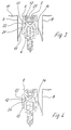
- Figure 4 shows the same section as in Figure 3, but with only one holder 8.
- the catch connection between a holder 8 is clear in these cuts and the adapter element 6 shown.
- the thin Sheet metal of the holder 8 engage securely and a particularly large tolerance range of compensate for different glass thicknesses or filling thicknesses.
- Figure 5 shows the adapter element 6 in a side view.
- the symmetrical one Adapter element 6 comprises the grooves 22 on the sides of the legs 13 and 14 are connectable with a holder 8 and the compensation of a larger tolerance range of filling panels.
- the projection 12 is turned inwards for secure positioning on the insulator profile 4.
- the adapter element 6 can also be coupled directly to the profile 1 of the supporting structure.
- the legs 13 and 14 are connected to a bridge 15.
- the bridge 15 has one U-shaped middle section 25, the adapter element 6 great flexibility gives, whereby the mounting of the adapter element 6 is easily possible.
- the Legs 13 and 14 can thereby be clipped onto the insulator profile 4 in a clamp-like manner become.
- the U-shaped middle section is dimensioned such that it fits into a fastening groove fits on the insulator profile 4 (see e.g. Figure 4).
- the adapter element 6 has at the end of the legs 13 and 14 to the axis of symmetry towards bevels 16 and 17, which is a simple plug on the Ensure isolator profile 4 and thus make assembly easier.
- the adapter element 6 is advantageously used as a plastic molding, preferably in one Length of approx. 50 mm, approximately corresponding to the length of a holder 8.
- Figure 6 shows again individual components in an exploded view and their Assembly sequence from bottom to top. So the isolator profile 4 is first in the Screw channel 3 of the profile 1 inserted and then fastened with the screw 5. Here you can see the small screw head 18, which is specially designed the mounting groove of the insulator profile 4 is adapted. Then the adapter element 6 clipped onto the insulating web 4, the projections 12 engaging in the grooves 24.
- the holder 8 has on the leg 19, which on the Grooves 22 of the adapter element 6 engages a crank 20, which improved Engagement in the grooves 22 allows. This increases the resting security.
Landscapes
- Engineering & Computer Science (AREA)
- Architecture (AREA)
- Physics & Mathematics (AREA)
- Electromagnetism (AREA)
- Civil Engineering (AREA)
- Structural Engineering (AREA)
- Load-Bearing And Curtain Walls (AREA)
- Securing Of Glass Panes Or The Like (AREA)
- Gates (AREA)
- Ladders (AREA)
- Bay Windows, Entrances, And Structural Adjustments Related Thereto (AREA)
Abstract
Description
- Fig. 1
- eine perspektivische Teilansicht eines Ausführungsbeispieles einer erfindungsgemäßen Haltevorrichtung;
- Fig. 2
- eine perspektivische Ansicht der Haltevorrichtung der Fig. 1 im montierten Zustand;
- Fig. 3
- eine geschnittene Teilansicht der Haltevorrichtung der Fig 2;
- Fig. 4
- eine geschnittene Teilansicht der Haltevorrichtung der Fig. 2 mit einseitigem Halteelement;
- Fig. 5
- eine Seitenansicht des Adapterelementes der Haltevorrichtung der Fig. 1, und
- Fig. 6
- eine Explosionsansicht der Haltevorrichtung.
- 1
- Profil
- 2
- Glasdichtung
- 3
- Schraubkanal
- 4
- Isolatorprofil
- 5
- Schraube
- 6
- Adapterelement
- 7
- Isolierglasscheibe
- 8
- Halter
- 9
- Ausnehmung
- 10
- Gewindeabschnitt
- 11
- Halteabschnitt
- 12
- Vorsprung
- 13
- Schenkel
- 14
- Schenkel
- 15
- Brücke
- 16
- Schräge
- 17
- Schräge
- 18
- Schraubenkopf
- 19
- Schenkel
- 20
- Kröpfung
- 21
- Rastzunge
- 22
- Rillen
- 24
- Nut
- 25
- Mittelabschnitt
Claims (11)
- In einem Glasfalz einer Fassade oder eines Lichtdaches vorgesehene Haltevorrichtung für Glasscheiben (7) oder Füllungsplatten, deren Außenränder an Dichtungen (2) anliegen, die mit einem Pfosten- oder Riegelprofil verbunden sind, mit einem Isolatorprofil (4) und einem Halter (8) mit einer Rastzunge (21), der an einer Seite einen Außenrand der Glasscheibe (7) oder der Füllungsplatte abstützt, dadurch gekennzeichnet, daß ein an dem Isolatorprofil (4) festlegbares Adapterelement (6) vorgesehen ist, das über Rastmittel (22) mit der Rastzunge (21) des Halters (8) verbunden ist.
- Haltevorrichtung nach Anspruch 1, dadurch gekennzeichnet, daß das Adapterelement (6) das Isolatorprofil (4) mit zwei integral ausgebildeten Schenkeln (23) im wesentlichen formschlüssig umgreift.
- Haltevorrichtung nach Anspruch 2, dadurch gekennzeichnet, daß an den Schenkeln (13, 14) des Adapterelementes (6) Rillen (22) für den Eingriff mit der Rastzunge (21) des Halters (8) ausgebildet sind.
- Haltevorrichtung nach einem der Ansprüche 1 bis 3, dadurch gekennzeichnet, daß das Adapterelement (6) an dem Isolatorprofil (4) verrastbar ist.
- Haltevorrichtung nach Anspruch 4, dadurch gekennzeichnet, daß an den Schenkeln (13, 14) des Adapterelementes (6) Vorsprünge (12) ausgebildet sind, die in korrespondierende Nuten (24) an dem Isolatorprofil (4) eingreifen.
- Haltevorrichtung nach einem oder mehreren der vorhergehenden Ansprüche 1 bis 5, dadurch gekennzeichnet, daß das Adapterelement (6) einen U-förmigen Mittelabschnitt (25) aufweist, dessen Schenkel sich im wesentlichen parallel zu den äußeren Schenkeln (13, 14) des Adapterelementes (6) erstrecken.
- Haltevorrichtung nach einem oder mehreren der vorhergehenden Ansprüche 1 bis 6, dadurch gekennzeichnet, daß das Adapterelement (6) als Spritzgußteil aus Kunststoff ausgebildet ist.
- Haltevorrichtung nach einem der Ansprüche 1 bis 7, dadurch gekennzeichnet, daß in dem Adapterelement (6) eine Aussparung (9) vorgesehen ist, durch die eine Schraube (5) zur Festlegung des Isolatorprofils (4) durchführbar ist.
- Haltevorrichtung nach einem oder mehreren der vorhergehenden Ansprüche 1 bis 8, dadurch gekennzeichnet, daß zur Festlegung des Isolatorprofils (4) eine Schraube (5) vorgesehen ist, deren Kopf (18) nur einen bis zu 1,4-fachen Durchmesser des Gewindeabschnittes (10) aufweist.
- Haltevorrichtung nach einem der Ansprüche 1 bis 9, dadurch gekennzeichnet, daß die Haltevorrichtung zu einer parallel zu den Schenkeln (13, 14) des Adapterelementes (6) verlaufenden Mittelebene symmetrisch ausgebildet ist.
- Haltevorrichtung nach einem der Ansprüche 1 bis 10, dadurch gekennzeichnet, daß die Rastzunge (21) des Halters (8) gekröpft ausgebildet ist.
Applications Claiming Priority (2)
| Application Number | Priority Date | Filing Date | Title |
|---|---|---|---|
| DE20015646U | 2000-09-09 | ||
| DE20015646U DE20015646U1 (de) | 2000-09-09 | 2000-09-09 | Haltevorrichtung für eine Riegel-Pfosten-Fassade |
Publications (3)
| Publication Number | Publication Date |
|---|---|
| EP1186723A2 true EP1186723A2 (de) | 2002-03-13 |
| EP1186723A3 EP1186723A3 (de) | 2003-01-08 |
| EP1186723B1 EP1186723B1 (de) | 2005-07-06 |
Family
ID=7946282
Family Applications (1)
| Application Number | Title | Priority Date | Filing Date |
|---|---|---|---|
| EP01121151A Expired - Lifetime EP1186723B1 (de) | 2000-09-09 | 2001-09-04 | Haltevorrichtung für eine Riegel-Pfosten-Fassade |
Country Status (3)
| Country | Link |
|---|---|
| EP (1) | EP1186723B1 (de) |
| AT (1) | ATE299210T1 (de) |
| DE (2) | DE20015646U1 (de) |
Cited By (3)
| Publication number | Priority date | Publication date | Assignee | Title |
|---|---|---|---|---|
| DE19651365C5 (de) * | 1996-12-10 | 2006-08-24 | Gerhard Kaese | Vorrichtung zur vorläufigen Halterung von Platten und Halterungen an Riegel- und Pfostenfassaden |
| DE202013103684U1 (de) | 2013-08-14 | 2014-11-17 | SCHÜCO International KG | Profil für Türen, Fenster, Blendrahmen oder Fassadenkonstruktionen |
| EP2586954A3 (de) * | 2011-10-27 | 2016-12-14 | Lindner Fassaden GmbH | Befestigungsvorrichtung für Fassadenelemente |
Families Citing this family (2)
| Publication number | Priority date | Publication date | Assignee | Title |
|---|---|---|---|---|
| DE20114225U1 (de) * | 2001-08-29 | 2001-10-31 | Schüco International KG, 33609 Bielefeld | Im Falzraum einer Fassade oder eines Lichtdaches festlegbare Haltevorrichtung |
| CN105401833A (zh) * | 2015-11-20 | 2016-03-16 | 安徽银盾斯金铝业有限公司 | 一种高铁用断桥隔热车窗铝合金型材 |
Citations (2)
| Publication number | Priority date | Publication date | Assignee | Title |
|---|---|---|---|---|
| DE19651365A1 (de) | 1996-12-10 | 1998-07-16 | Gerhard Kaese | Vorrichtung zur vorläufigen Halterung von Platten und Halterungen an Riegel- und Pfostenfassaden |
| DE29903658U1 (de) | 1999-03-01 | 1999-06-02 | Schüco International KG, 33609 Bielefeld | Haltevorrichtung für Glasscheiben oder Füllungsplatten einer Fassade oder eines Lichtdachs |
Family Cites Families (1)
| Publication number | Priority date | Publication date | Assignee | Title |
|---|---|---|---|---|
| DE19603433C2 (de) * | 1996-01-31 | 1998-05-14 | Gerhard Kaese | Vorrichtung zur vorläufigen Halterung von Einsatzteilen in Riegel- und Pfostenfassaden |
-
2000
- 2000-09-09 DE DE20015646U patent/DE20015646U1/de not_active Expired - Lifetime
-
2001
- 2001-09-04 AT AT01121151T patent/ATE299210T1/de not_active IP Right Cessation
- 2001-09-04 EP EP01121151A patent/EP1186723B1/de not_active Expired - Lifetime
- 2001-09-04 DE DE50106674T patent/DE50106674D1/de not_active Expired - Lifetime
Patent Citations (2)
| Publication number | Priority date | Publication date | Assignee | Title |
|---|---|---|---|---|
| DE19651365A1 (de) | 1996-12-10 | 1998-07-16 | Gerhard Kaese | Vorrichtung zur vorläufigen Halterung von Platten und Halterungen an Riegel- und Pfostenfassaden |
| DE29903658U1 (de) | 1999-03-01 | 1999-06-02 | Schüco International KG, 33609 Bielefeld | Haltevorrichtung für Glasscheiben oder Füllungsplatten einer Fassade oder eines Lichtdachs |
Cited By (3)
| Publication number | Priority date | Publication date | Assignee | Title |
|---|---|---|---|---|
| DE19651365C5 (de) * | 1996-12-10 | 2006-08-24 | Gerhard Kaese | Vorrichtung zur vorläufigen Halterung von Platten und Halterungen an Riegel- und Pfostenfassaden |
| EP2586954A3 (de) * | 2011-10-27 | 2016-12-14 | Lindner Fassaden GmbH | Befestigungsvorrichtung für Fassadenelemente |
| DE202013103684U1 (de) | 2013-08-14 | 2014-11-17 | SCHÜCO International KG | Profil für Türen, Fenster, Blendrahmen oder Fassadenkonstruktionen |
Also Published As
| Publication number | Publication date |
|---|---|
| EP1186723A3 (de) | 2003-01-08 |
| ATE299210T1 (de) | 2005-07-15 |
| EP1186723B1 (de) | 2005-07-06 |
| DE50106674D1 (de) | 2005-08-11 |
| DE20015646U1 (de) | 2000-11-30 |
Similar Documents
| Publication | Publication Date | Title |
|---|---|---|
| EP0501994B1 (de) | Verbindungsformstück für bauprofile | |
| DE4309088C2 (de) | Ortsfest einbaubare Scheibe für Kraftfahrzeuge | |
| EP0528213B1 (de) | Beschlagteil zur Klemmbefestigung in einer mindestens einseitigen hinterschnittenen Profilnut | |
| EP0056484A2 (de) | Mit einem Stulpschienenbeschlag ausgerüsteter Tür- oder Fensterflügel | |
| EP0478877A1 (de) | Vorrichtung zum lösbaren Verbinden zweier Profilstäbe | |
| EP0369326B1 (de) | Isolierende Verbindungsvorrichtung für Bauplatten | |
| EP1840315A2 (de) | Rahmenkonstruktion | |
| DE3319627C2 (de) | Eckverbindung | |
| DE8712171U1 (de) | Positioniervorrichtung sowie damit versehener Gleitklotz und Spannanker zum Festlegen von Werkstücken an einer Werkzeugmaschine | |
| EP1186723B1 (de) | Haltevorrichtung für eine Riegel-Pfosten-Fassade | |
| EP2754803B1 (de) | Riegelstangenbeschlag für ein Fenster oder eine Tür und Riegelstange für einen solchen Riegelstangenbeschlag | |
| EP1522668B1 (de) | Verbinder für Doppelfenster-Rahmenprofile | |
| EP0067970B1 (de) | Befestigungsvorrichtung für Fassadenelemente an einer Gebäudeaussenwand | |
| EP1840314A2 (de) | Rahmenkonstruktion aus Rahmenholmen für ein zusammengesetztes Bauelement | |
| EP2455574B1 (de) | Fenster- oder Türrahmen | |
| EP3369946B1 (de) | Flachdübel und verfahren zum anbringen eines flachdübels in einer mauer | |
| EP0111185B1 (de) | Rahmen, insbesondere für eine Duschtrennwand | |
| DE4441769C2 (de) | Steckverbinder für Sprossenprofile | |
| DE3103291C2 (de) | An Blend- und Flügelrahmen von Fenstern, Türen od.dgl. ansetzbares einteiliges Verbindungselement | |
| EP1469157B1 (de) | Schliessleiste | |
| DE19917036C2 (de) | Sprossenfenster | |
| DE29502101U1 (de) | Verbindung von flächigen, miteinander fluchtenden Planteilen | |
| DE2553509C2 (de) | Vorrichtung zum Verbinden eines Deckprofils mit einem Rahmenprofil | |
| DE29516689U1 (de) | Bauelemente für Gestelle, Wandkonstruktionen o.dgl. | |
| EP2088335A2 (de) | Profilverbinder |
Legal Events
| Date | Code | Title | Description |
|---|---|---|---|
| PUAI | Public reference made under article 153(3) epc to a published international application that has entered the european phase |
Free format text: ORIGINAL CODE: 0009012 |
|
| AK | Designated contracting states |
Kind code of ref document: A2 Designated state(s): AT BE CH CY DE DK ES FI FR GB GR IE IT LI LU MC NL PT SE TR |
|
| AX | Request for extension of the european patent |
Free format text: AL;LT PAYMENT 20010905;LV PAYMENT 20010905;MK;RO;SI |
|
| PUAL | Search report despatched |
Free format text: ORIGINAL CODE: 0009013 |
|
| AK | Designated contracting states |
Kind code of ref document: A3 Designated state(s): AT BE CH CY DE DK ES FI FR GB GR IE IT LI LU MC NL PT SE TR |
|
| AX | Request for extension of the european patent |
Free format text: AL;LT PAYMENT 20010905;LV PAYMENT 20010905;MK;RO;SI |
|
| 17P | Request for examination filed |
Effective date: 20030226 |
|
| AKX | Designation fees paid |
Designated state(s): AT BE CH CY DE DK ES FI FR GB GR IE IT LI LU MC NL PT SE TR |
|
| AXX | Extension fees paid |
Extension state: LT Payment date: 20010905 Extension state: SI Payment date: 20030226 Extension state: LV Payment date: 20010905 |
|
| 17Q | First examination report despatched |
Effective date: 20040122 |
|
| GRAP | Despatch of communication of intention to grant a patent |
Free format text: ORIGINAL CODE: EPIDOSNIGR1 |
|
| GRAS | Grant fee paid |
Free format text: ORIGINAL CODE: EPIDOSNIGR3 |
|
| GRAA | (expected) grant |
Free format text: ORIGINAL CODE: 0009210 |
|
| AK | Designated contracting states |
Kind code of ref document: B1 Designated state(s): AT BE CH CY DE DK ES FI FR GB GR IE IT LI LU MC NL PT SE TR |
|
| AX | Request for extension of the european patent |
Extension state: LT LV SI |
|
| PG25 | Lapsed in a contracting state [announced via postgrant information from national office to epo] |
Ref country code: IT Free format text: LAPSE BECAUSE OF FAILURE TO SUBMIT A TRANSLATION OF THE DESCRIPTION OR TO PAY THE FEE WITHIN THE PRESCRIBED TIME-LIMIT;WARNING: LAPSES OF ITALIAN PATENTS WITH EFFECTIVE DATE BEFORE 2007 MAY HAVE OCCURRED AT ANY TIME BEFORE 2007. THE CORRECT EFFECTIVE DATE MAY BE DIFFERENT FROM THE ONE RECORDED. Effective date: 20050706 Ref country code: FI Free format text: LAPSE BECAUSE OF FAILURE TO SUBMIT A TRANSLATION OF THE DESCRIPTION OR TO PAY THE FEE WITHIN THE PRESCRIBED TIME-LIMIT Effective date: 20050706 Ref country code: NL Free format text: LAPSE BECAUSE OF FAILURE TO SUBMIT A TRANSLATION OF THE DESCRIPTION OR TO PAY THE FEE WITHIN THE PRESCRIBED TIME-LIMIT Effective date: 20050706 Ref country code: TR Free format text: LAPSE BECAUSE OF FAILURE TO SUBMIT A TRANSLATION OF THE DESCRIPTION OR TO PAY THE FEE WITHIN THE PRESCRIBED TIME-LIMIT Effective date: 20050706 Ref country code: GB Free format text: LAPSE BECAUSE OF FAILURE TO SUBMIT A TRANSLATION OF THE DESCRIPTION OR TO PAY THE FEE WITHIN THE PRESCRIBED TIME-LIMIT Effective date: 20050706 Ref country code: IE Free format text: LAPSE BECAUSE OF FAILURE TO SUBMIT A TRANSLATION OF THE DESCRIPTION OR TO PAY THE FEE WITHIN THE PRESCRIBED TIME-LIMIT Effective date: 20050706 |
|
| REG | Reference to a national code |
Ref country code: GB Ref legal event code: FG4D Free format text: NOT ENGLISH |
|
| REG | Reference to a national code |
Ref country code: CH Ref legal event code: EP |
|
| REG | Reference to a national code |
Ref country code: IE Ref legal event code: FG4D Free format text: LANGUAGE OF EP DOCUMENT: GERMAN |
|
| REF | Corresponds to: |
Ref document number: 50106674 Country of ref document: DE Date of ref document: 20050811 Kind code of ref document: P |
|
| PG25 | Lapsed in a contracting state [announced via postgrant information from national office to epo] |
Ref country code: CY Free format text: LAPSE BECAUSE OF FAILURE TO SUBMIT A TRANSLATION OF THE DESCRIPTION OR TO PAY THE FEE WITHIN THE PRESCRIBED TIME-LIMIT Effective date: 20050904 Ref country code: AT Free format text: LAPSE BECAUSE OF NON-PAYMENT OF DUE FEES Effective date: 20050904 |
|
| PG25 | Lapsed in a contracting state [announced via postgrant information from national office to epo] |
Ref country code: LU Free format text: LAPSE BECAUSE OF NON-PAYMENT OF DUE FEES Effective date: 20050930 Ref country code: BE Free format text: LAPSE BECAUSE OF NON-PAYMENT OF DUE FEES Effective date: 20050930 Ref country code: CH Free format text: LAPSE BECAUSE OF NON-PAYMENT OF DUE FEES Effective date: 20050930 Ref country code: LI Free format text: LAPSE BECAUSE OF NON-PAYMENT OF DUE FEES Effective date: 20050930 Ref country code: MC Free format text: LAPSE BECAUSE OF NON-PAYMENT OF DUE FEES Effective date: 20050930 |
|
| PG25 | Lapsed in a contracting state [announced via postgrant information from national office to epo] |
Ref country code: GR Free format text: LAPSE BECAUSE OF FAILURE TO SUBMIT A TRANSLATION OF THE DESCRIPTION OR TO PAY THE FEE WITHIN THE PRESCRIBED TIME-LIMIT Effective date: 20051006 Ref country code: SE Free format text: LAPSE BECAUSE OF FAILURE TO SUBMIT A TRANSLATION OF THE DESCRIPTION OR TO PAY THE FEE WITHIN THE PRESCRIBED TIME-LIMIT Effective date: 20051006 Ref country code: DK Free format text: LAPSE BECAUSE OF FAILURE TO SUBMIT A TRANSLATION OF THE DESCRIPTION OR TO PAY THE FEE WITHIN THE PRESCRIBED TIME-LIMIT Effective date: 20051006 |
|
| PG25 | Lapsed in a contracting state [announced via postgrant information from national office to epo] |
Ref country code: ES Free format text: LAPSE BECAUSE OF FAILURE TO SUBMIT A TRANSLATION OF THE DESCRIPTION OR TO PAY THE FEE WITHIN THE PRESCRIBED TIME-LIMIT Effective date: 20051017 |
|
| PG25 | Lapsed in a contracting state [announced via postgrant information from national office to epo] |
Ref country code: PT Free format text: LAPSE BECAUSE OF FAILURE TO SUBMIT A TRANSLATION OF THE DESCRIPTION OR TO PAY THE FEE WITHIN THE PRESCRIBED TIME-LIMIT Effective date: 20051212 |
|
| LTIE | Lt: invalidation of european patent or patent extension |
Effective date: 20050706 |
|
| NLV1 | Nl: lapsed or annulled due to failure to fulfill the requirements of art. 29p and 29m of the patents act | ||
| GBV | Gb: ep patent (uk) treated as always having been void in accordance with gb section 77(7)/1977 [no translation filed] |
Effective date: 20050706 |
|
| REG | Reference to a national code |
Ref country code: IE Ref legal event code: FD4D |
|
| PLBE | No opposition filed within time limit |
Free format text: ORIGINAL CODE: 0009261 |
|
| STAA | Information on the status of an ep patent application or granted ep patent |
Free format text: STATUS: NO OPPOSITION FILED WITHIN TIME LIMIT |
|
| REG | Reference to a national code |
Ref country code: CH Ref legal event code: PL |
|
| 26N | No opposition filed |
Effective date: 20060407 |
|
| EN | Fr: translation not filed | ||
| PG25 | Lapsed in a contracting state [announced via postgrant information from national office to epo] |
Ref country code: FR Free format text: LAPSE BECAUSE OF FAILURE TO SUBMIT A TRANSLATION OF THE DESCRIPTION OR TO PAY THE FEE WITHIN THE PRESCRIBED TIME-LIMIT Effective date: 20060901 |
|
| BERE | Be: lapsed |
Owner name: SCHUCO INTERNATIONAL K.G. Effective date: 20050930 |
|
| PG25 | Lapsed in a contracting state [announced via postgrant information from national office to epo] |
Ref country code: FR Free format text: LAPSE BECAUSE OF FAILURE TO SUBMIT A TRANSLATION OF THE DESCRIPTION OR TO PAY THE FEE WITHIN THE PRESCRIBED TIME-LIMIT Effective date: 20050930 |
|
| PG25 | Lapsed in a contracting state [announced via postgrant information from national office to epo] |
Ref country code: FR Free format text: LAPSE BECAUSE OF FAILURE TO SUBMIT A TRANSLATION OF THE DESCRIPTION OR TO PAY THE FEE WITHIN THE PRESCRIBED TIME-LIMIT Effective date: 20050706 |
|
| PGFP | Annual fee paid to national office [announced via postgrant information from national office to epo] |
Ref country code: DE Payment date: 20141003 Year of fee payment: 14 |
|
| REG | Reference to a national code |
Ref country code: DE Ref legal event code: R119 Ref document number: 50106674 Country of ref document: DE |
|
| PG25 | Lapsed in a contracting state [announced via postgrant information from national office to epo] |
Ref country code: DE Free format text: LAPSE BECAUSE OF NON-PAYMENT OF DUE FEES Effective date: 20160401 |