EP1184572A2 - Addichtungsvorrichtung für einen Übergangsbereich an Hochdruckbauteilen - Google Patents
Addichtungsvorrichtung für einen Übergangsbereich an Hochdruckbauteilen Download PDFInfo
- Publication number
- EP1184572A2 EP1184572A2 EP01117578A EP01117578A EP1184572A2 EP 1184572 A2 EP1184572 A2 EP 1184572A2 EP 01117578 A EP01117578 A EP 01117578A EP 01117578 A EP01117578 A EP 01117578A EP 1184572 A2 EP1184572 A2 EP 1184572A2
- Authority
- EP
- European Patent Office
- Prior art keywords
- pressure seal
- seal
- sealing device
- pressure
- high pressure
- Prior art date
- Legal status (The legal status is an assumption and is not a legal conclusion. Google has not performed a legal analysis and makes no representation as to the accuracy of the status listed.)
- Granted
Links
Images




Classifications
-
- F—MECHANICAL ENGINEERING; LIGHTING; HEATING; WEAPONS; BLASTING
- F04—POSITIVE - DISPLACEMENT MACHINES FOR LIQUIDS; PUMPS FOR LIQUIDS OR ELASTIC FLUIDS
- F04B—POSITIVE-DISPLACEMENT MACHINES FOR LIQUIDS; PUMPS
- F04B1/00—Multi-cylinder machines or pumps characterised by number or arrangement of cylinders
- F04B1/04—Multi-cylinder machines or pumps characterised by number or arrangement of cylinders having cylinders in star- or fan-arrangement
- F04B1/0404—Details or component parts
- F04B1/0448—Sealing means, e.g. for shafts or housings
-
- F—MECHANICAL ENGINEERING; LIGHTING; HEATING; WEAPONS; BLASTING
- F04—POSITIVE - DISPLACEMENT MACHINES FOR LIQUIDS; PUMPS FOR LIQUIDS OR ELASTIC FLUIDS
- F04B—POSITIVE-DISPLACEMENT MACHINES FOR LIQUIDS; PUMPS
- F04B53/00—Component parts, details or accessories not provided for in, or of interest apart from, groups F04B1/00 - F04B23/00 or F04B39/00 - F04B47/00
- F04B53/007—Cylinder heads
-
- F—MECHANICAL ENGINEERING; LIGHTING; HEATING; WEAPONS; BLASTING
- F04—POSITIVE - DISPLACEMENT MACHINES FOR LIQUIDS; PUMPS FOR LIQUIDS OR ELASTIC FLUIDS
- F04B—POSITIVE-DISPLACEMENT MACHINES FOR LIQUIDS; PUMPS
- F04B53/00—Component parts, details or accessories not provided for in, or of interest apart from, groups F04B1/00 - F04B23/00 or F04B39/00 - F04B47/00
- F04B53/16—Casings; Cylinders; Cylinder liners or heads; Fluid connections
-
- F—MECHANICAL ENGINEERING; LIGHTING; HEATING; WEAPONS; BLASTING
- F02—COMBUSTION ENGINES; HOT-GAS OR COMBUSTION-PRODUCT ENGINE PLANTS
- F02M—SUPPLYING COMBUSTION ENGINES IN GENERAL WITH COMBUSTIBLE MIXTURES OR CONSTITUENTS THEREOF
- F02M2200/00—Details of fuel-injection apparatus, not otherwise provided for
- F02M2200/16—Sealing of fuel injection apparatus not otherwise provided for
-
- F—MECHANICAL ENGINEERING; LIGHTING; HEATING; WEAPONS; BLASTING
- F02—COMBUSTION ENGINES; HOT-GAS OR COMBUSTION-PRODUCT ENGINE PLANTS
- F02M—SUPPLYING COMBUSTION ENGINES IN GENERAL WITH COMBUSTIBLE MIXTURES OR CONSTITUENTS THEREOF
- F02M59/00—Pumps specially adapted for fuel-injection and not provided for in groups F02M39/00 -F02M57/00, e.g. rotary cylinder-block type of pumps
- F02M59/44—Details, components parts, or accessories not provided for in, or of interest apart from, the apparatus of groups F02M59/02 - F02M59/42; Pumps having transducers, e.g. to measure displacement of pump rack or piston
Definitions
- the present invention relates to a sealing device for a transition area on high pressure components and in particular a sealing device for transition areas on pump components of pumps for common rail systems.
- FIG. 11 there is a known high pressure seal 1 for a common rail system, which on a Transition area 5 between a first component 2 and a second component 3 is used to continue to enable a fluid channel 6.
- High-pressure seal 1 consists of two elements, namely one Sealing ring 24 and a support ring 25, which in a recess 4 are arranged, which are formed in the first component 2 is.
- the sealing ring 24 is made of an elastomer.
- the support ring 25 is on the outer circumference of the sealing ring 24 arranged to the sealing ring 24 against the high pressures in the Support common rail.
- the support ring has none Sealing function.
- a valve 26 is arranged first to the second component, which essentially from a valve ball 22, a spring element 27 and a basket-shaped ball cage 28.
- high pressure seals are disadvantageous that they are not over the entire temperature range seal completely. Especially at low temperatures are the sealing properties of the well-known high pressure seals not sufficient, often causing leakage occurs to the outside. This results in sealing problems in particular when starting a cold engine, especially in winter because the sealing ring withstands the high pressures in the common rail system (up to approx. 1800 bar) does not withstand. Further the known high pressure seals are disadvantageous in that that depends on the operating loads (pressure, forces) there is a gap in the transition region 5. From a certain The gap size or frequency of the gap change is the Elastomeric ring is no longer able to pass this transition area seal. This leads to undesirable leaks during of the company.
- a sealing device Sealing high pressure components at a transition area provided on a high pressure line, which has a high pressure seal with a substantially annular shape and includes a low pressure seal.
- the high pressure seal is at a line transition of the high pressure components arranged.
- the low pressure seal is outside the high pressure seal arranged to prevent any leakage to seal securely to the outside thanks to the high pressure seal. So there is a redundant sealing system, which is an escape of fluid at transition areas of high pressure components can reliably prevent. Therefore can occur in the event of leakage through the high pressure seal retained by the low pressure seal become. Accordingly, the combination of a high pressure seal and a low pressure seal reliably prevents leakage prevent.
- the present invention can be found in a common rail system at transitions between pump components be used.
- the high pressure seal is made of metal. Further is the inventive high pressure seal made of metal preloaded when assembled. Thereby can be achieved that the high pressure seal after the Assembly due to their preload with high pressure on their Contact surfaces for sealing.
- a high-pressure seal according to the invention provides a seal, which over the entire temperature range ensures adequate sealing without leakage, especially in the lower temperature range.
- the combination of the preload of the seal and of the sealing ring made of metal is a dynamically resilient High pressure seal provided, which in particular Pressure pulsations with a high frequency can follow and thus no leaks due to fluid-induced Has stress pulses.
- the invention requires High pressure seal also no support ring, because they are adequate due to their manufacture from a metal Resistance to high pressures. moreover is the high pressure seal made of metal against aggressive Media resistant.
- the high-pressure seal is preferably made of spring plate or made of steel. This can be an inexpensive and easy to manufacture high pressure seal can be obtained. When producing the seal from spring plate, the further also a particularly simple prestressing of the seal be realized.
- the high-pressure seal made of temperature-resistant Plastic or made of rubber. Particularly preferred an elastomer is used as the plastic.
- the low pressure seal made of metal or made of plastic or rubber or from one with plastic coated metal.
- the low pressure seal is preferably a flat seal or designed as a profile seal. Particularly preferred the low pressure seal has a bead.
- the high pressure seal as a ring with a C-shaped Cross section formed.
- the open area of the C-shaped ring directed inwards. Due to the C-shaped design of the high pressure seal in particular, that the seal is additionally achieved through the fluid pressure with great force against their contact surfaces is pressed because the fluid pressure in the direction of the contact surface is directed.
- the existing contact pressure due to the geometric Design of the seal in C-shape reinforced.
- Can continue the C-ring-shaped high pressure seal also deforms components, which arise due to the high pressures, very good compensate for the fact that due to its C-shape it especially the extensions and the approaches, neighboring Components can follow easily due to the high pressure.
- the high-pressure seal which is C-shaped in cross section is particularly preferred a symmetrical shape, so that a mix-up is guaranteed.
- the high-pressure seal advantageously has two sealing surfaces or three sealing surfaces.
- the seal can thus be arranged such that it has an upper and a lower contact surface for sealing. It is also possible to have a third contact surface through the outward circular section of the C-shaped sealing ring is formed.
- the high pressure seal as a ring with a angular cross section.
- This has so-called wedge ring in the unassembled state one leg angle, i.e. an angle between his two legs, from significantly larger than 90 °. For example, this leg angle is approx. 115 ° when not installed.
- the one leg When assembled the one leg is attached to an area of the one component pressed. The other leg is against the sealing surface of the second component pressed.
- This is the leg angle the wedge ring when installed is significantly smaller than in the unassembled state and is approx. 90 ° to 95 °.
- both legs of the wedge ring lie directly on the sealing surfaces of the two components, so that a very secure seal is achieved.
- the wedge ring is made of metal e.g. a sheet (spring sheet) manufactured.
- the high-pressure seal preferably has a cross section tapered area.
- This can, for example a wedge-shaped seal can be provided.
- the wedge-shaped surface of the seal is on the inside of the seal directed. It is particularly preferred tapered area parabolic or rectilinear in section educated.
- the high pressure seal has in addition to that tapered area an area with constant internal and outside diameter.
- one of the Contact surfaces for sealing are relatively large.
- the high pressure seal has a central connection area on which has at least one through opening having.
- the middle connection area connects the outer ones Ring areas of the seal with each other. This allows the The stability of the high pressure seal can be increased.
- the high-pressure seal is advantageously designed in the form of a button.
- the high pressure seal has a flat circular shape middle connection area so that the high pressure seal e.g. as a cage or stop for a valve body can be used.
- the high pressure seal e.g. as a cage or stop for a valve body can be used.
- the high pressure seal with a cage for a valve body combined to retain a valve body. Consequently the high pressure seal has both a sealing function as well as a retention function for a valve body valve located immediately before the seal.
- the button-shaped high-pressure seal is preferably included four through openings are provided to ensure adequate To ensure fluid flow.
- the middle connection area at one in cross section C-shaped ring formed at one end in the vertical direction. This enables the advantages of the C-shaped high pressure seal with those of the middle connection area combine.
- the central connection area preferably serves as a stop for the valve body. This makes it particularly easy Construction of the high pressure seal and one immediately valve adjacent to the seal.
- the present invention provides a redundant sealing device through a combination of a high pressure seal ready with a low pressure seal.
- the sealing device has a simple structure and enables over the entire temperature range in which the Combination seal is used, a reliable seal without leakage problems, especially in the low temperature range.
- This is further combined by a high pressure sealing made of metal and the preload the seal is further reinforced, so that excellent sealing properties can be provided.
- the sealing device according to the invention an insensitivity to load pulses occurring in the delivery fluid achieved, which with the previously used Elastomer seals were not given.
- it can sealing system according to the invention also as a cage or stop can be used for a valve body and is durable against aggressive media.
- Figures 1 and 2 is a high pressure seal 1 for a Sealing device according to a first embodiment of the present invention.
- the high pressure seal 1 is at a transition area 5 between a first component 2 (e.g. a cylinder) and a second component 3 (e.g. a cylinder head). There is a recess 4 on the first component 2 for receiving the high pressure seal 1 provided (see FIG. 1). At the transition area 5 opens a fluid channel 6 of the first component 2, which is continued in the second component 3. The recess 4 is formed around the mouth of the fluid channel 6. The high-pressure seal 1 must therefore cover the transition area 5 Seal around the fluid channel 6 to prevent fluid leakage to prevent.
- the high-pressure seal 1 an annular shape. Further, as can be seen from Figure 1 is, the high pressure seal 1 has a C-shaped Cross section on.
- the high-pressure seal shows 1 a first straight section 7, a curved section 8 and a second straight section 9.
- the two straight sections 7 and 9 lie with their flat surfaces on the first or second component and thus form annular Sealing areas 10 and 11 in the form of line seals.
- the curved section 8 is designed such that he is in contact with the side wall of the recess 4 comes and thus an additional third sealing area 30 forms.
- the C-shaped High-pressure seal is completely curved, i.e. is formed without straight sections or such that he only has two sealing areas, e.g. B. the two sealing areas 10 and 11.
- the C-shaped high pressure seal 1 has its entire Cross-section has a constant thickness. However, it is also possible that the high pressure seal, especially if made of sheet metal or similar is produced, different in cross section Has thicknesses.
- the high-pressure seal 1 points in the vertical direction, i.e. in the direction of the central axis 0-0, one at one end Inside diameter D1 and at the other end an inside diameter D2 on.
- the inside diameter is D1 equal to the inside diameter D2, so the high pressure seal 1 is symmetrical.
- the high pressure seal 1 of the first embodiment is made of spring steel and the two straight sections 7 and 9 are biased outwards so that they are installed Condition against the wall surfaces of the first and second Component 2 and 3 are pressed. Due to the concave arrangement of the curved area 8 to the fluid channel 6 supported the fluid pressure the pressing of the straight regions 7 and 9 against the respective contact surfaces of the first and second Component.
- the C-ring-shaped high pressure seal 1 is constructed symmetrically is the same at both ends in the vertical direction Has inner diameter D1 and D2, the pressing forces the same at all points of the high pressure seal 1. Consequently can secure sealing of the transition region 5 is achieved become. Since the preload of the high pressure seal 1 over the entire temperature range is one adequate sealing, especially at low temperatures guaranteed. Furthermore, you can also easily high-frequency pressure pulsations are recorded in the fluid and Component deformations due to the high pressure compensated become. Furthermore, the symmetrical structure of the High pressure seal 1 ensures a mix-up-free installation and the high pressure seal is against aggressive Media resistant.
- FIG 3 is the sealing device according to the invention with the C-ring-shaped high pressure seal 1 according to the first Embodiment shown.
- the sealing device comprises the high pressure seal and a low pressure seal 12.
- the high pressure seal 1 seals a transition area between a cylinder block 2 and a cylinder head 3 a fluid channel 6.
- the high pressure seal 1 is in a on the cylinder block 2 formed annular recess 4 inserted.
- Between cylinder head 3 and cylinder block 2 is further the low-pressure seal 12 designed as a flat seal arranged.
- the low pressure seal 12 is one with a Sheet with an elastomer coating and can also have one Have a bead.
- the transition area on the fluid channel 6 sealed twice by the sealing device, namely by the high pressure seal 1 and the low pressure seal 12.
- the two seals are in the assembled state 1 and 12 of the sealing device essentially in one level at the transition area 5.
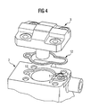
- FIG 4 is a sealing device according to a second Embodiment shown.
- the second embodiment corresponds essentially to that shown in FIG first embodiment.
- the flat gasket Form seal or profile seal 12 is provided, which in a corresponding recess 13 inserted in the cylinder block 2 becomes.
- the molded seal 12 is outside the high pressure seal 1 arranged so that a direct connection from the High pressure seal 1 to the low pressure area guaranteed is.
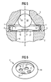
- FIGS A high-pressure seal 1 is shown in FIGS Use in a sealing device according to the invention according to a third embodiment of the present invention shown. Same or functionally the same parts have the same reference numerals as in the first embodiment designated. Because the third embodiment corresponds essentially to the first exemplary embodiment, are only the differences between the two below Exemplary embodiments described in detail.
- the high pressure seal 1 is for one Sealing device at a transition area 5 of a fluid channel 6 between a first component 2 and a second Component 3 arranged.
- the high pressure seal 1 is, as shown in Figures 5 and 6, button-shaped.
- a C-ring-shaped edge region 16 one of its sides in the vertical direction (i.e. in the direction the center line 0-0) a middle connection area 17 on.
- a first straight section 7 a curved section 8 and a second straight section 9 formed C-shaped edge area 16 at its second straight section 9 with the middle connection area 17 connected.
- the second straight section 9 goes in the middle connection area over.
- the section 7 can also be curved.
- a valve ball 22 is provided, which on a Valve seat 23 abuts.
- a valve is formed.
- the button-shaped high-pressure seal 1 forms the ball cage for the valve ball 22.
- the in Area of the midline 0-0 lying section of the middle Connection area 17 a greater thickness than the edge area 16 to provide sufficient strength for retention to provide the valve ball 22.
- the high-pressure seal 1 for a sealing device according to the third embodiment in addition to the Sealing function also a retention function for the Valve ball 22 on.
- the high pressure seal 1 made of metal e.g. made of spring steel, can be made. It is also possible to choose between the as Cage serving high pressure seal and the valve ball still to arrange a spring element so that a check valve in Fluid channel 6 arranged between the first and the second component is.
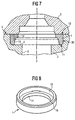
- FIG. 7 and 8 is a high pressure seal 1 for a Sealing device according to a fourth embodiment of the present invention. Same or Functionally identical parts have the same reference symbols as referred to in the previously described embodiments. Since the fourth embodiment essentially corresponds to the previously described exemplary embodiments, are only the differences to the exemplary embodiments described in detail.
- the high pressure seal 1 is at one Transition area 5 between a first component 2 and arranged a second component 3. It is in one Recess 4 positioned, which is formed in the first component 2 is and seals a transition of a fluid channel 6.
- the high-pressure seal 1 a first area 14 and a second area 15.
- the first area 14 has a constant inside and outside diameter and therefore has a rectangular section Shape up. However, the first area 14 can also be different Have inside and outside diameter.
- the second Area 15 tapers starting from the first area 14 to its outside. As shown in Figure 7, the is tapering region 15 is parabolic in section.
- This configuration of the high-pressure seal according to the invention 1 arise at the contact surfaces of the seal 1 different areas for the first and second component of sealing areas 10 and 11.
- the wedge ring-shaped High pressure seal 1 To on both sealing areas to get a surface pressure, the wedge ring-shaped High pressure seal 1 to one side accordingly biased.
- the high pressure seal is pressed 1 to areas 10 and 11 and towards the center line 0-0 extending area 30 of the recess 4.
- To a to obtain additional prestressing of the high pressure seal 1, are the sealing areas 10 and 30 of the seal 1 in the unassembled state to each other at an angle of greater arranged as 90 ° - 95 °.
- the sealing areas are in the assembled state 10 and 30 then at an angle of 90 ° - 95 ° arranged to each other.
- the high pressure seal 1 according to the fourth Embodiment a sufficient sealing function very high pressures and is insensitive to the fluid occurring high-frequency pressure pulsations and resistant to PME fluids.
- FIG. 9 and 10 is a high pressure seal 1 for a sealing device according to a fifth embodiment of the present invention. Same or Functionally identical parts have the same reference symbols as referred to in the previously described embodiments. Since the fifth embodiment essentially corresponds to the previously described exemplary embodiments, are only the differences to the exemplary embodiments described in detail.
- the high pressure seal is 1 for the sealing device as a so-called wedge seal educated.
- the wedge seal 1 is annular and includes a first leg 31 and a second Leg 32.
- the two legs 31 and 32 have the same length. You can but also have different lengths.
- the high-pressure seal 1 is provided in a component 2 Recess 4 arranged.
- the depth corresponds to the Recess 4 essentially the length of the leg of the leg 32.
- the high-pressure seal 1 is in an intermediate assembly step shown.
- the high pressure seal 1 inserted into the recess 4.
- sealing device according to the invention from any combination of those previously described High pressure seals or low pressure seals can be formed.
- the present invention relates to a sealing device with a high pressure seal 1 and one Low pressure seal 12 for sealing a transition area 5 on a high-pressure line 6, which in particular is used in common rail systems.
- the high pressure seal 1 has a substantially annular shape and is arranged at the line transition of the high pressure components 2, 3.
- the low pressure seal 12 is in one plane with the high-pressure seal 1 arranged around it to a Any leakage that may occur through the high pressure seal 1 to seal to the outside.
- a reliable, redundant seal are provided which dynamic across the entire operating temperature range resilient high-pressure sealing ring 1 and also for one Use with aggressive media is suitable.
Landscapes
- Engineering & Computer Science (AREA)
- Mechanical Engineering (AREA)
- General Engineering & Computer Science (AREA)
- Gasket Seals (AREA)
Abstract
Description
- Figur 1
- eine schematische Schnittansicht einer Hochdruckabdichtung für eine Abdichtungsvorrichtung gemäß einem ersten Ausführungsbeispiel der vorliegenden Erfindung im eingebauten Zustand;
- Figur 2
- eine perspektivische Ansicht der in Figur 1 gezeigten Hochdruckabdichtung;
- Figur 3
- eine perspektivische Explosionsdarstellung der Anordnung der Abdichtungsvorrichtung gemäß dem ersten Ausführungsbeispiel;
- Figur 4
- eine perspektivische Explosionsdarstellung einer Abdichtungsvorrichtung gemäß einem zweiten Ausführungsbeispiel der vorliegenden Erfindung;
- Figur 5
- eine schematische Schnittansicht einer Hochdruckabdichtung für eine Abdichtungsvorrichtung gemäß einem dritten Ausführungsbeispiel der vorliegenden Erfindung im eingebauten Zustand;
- Figur 6
- eine perspektivische Ansicht der in Figur 5 gezeigten Hochdruckabdichtung;
- Figur 7
- eine schematische Schnittansicht einer Hochdruckabdichtung für eine Abdichtungsvorrichtung gemäß einem vierten Ausführungsbeispiel der vorliegenden Erfindung im eingebauten Zustand;
- Figur 8
- eine perspektivische Ansicht der in Figur 7 gezeigten Hochdruckabdichtung;
- Figur 9
- eine schematische Schnittansicht einer Hochdruckabdichtung für eine Abdichtungsvorrichtung gemäß einem fünften Ausführungsbeispiel im teilmontierten Zustand;
- Figur 10
- eine schematische Schnittansicht der in Figur 9 gezeigten Hochdruckabdichtung im endmontierten Zustand und
- Figur 11
- eine schematische Schnittansicht einer Hochdruckabdichtung gemäß dem Stand der Technik.
Claims (21)
- Abdichtungsvorrichtung für einen Übergangsbereich (5) an Hochdruckbauteilen (2, 3), insbesondere Pumpenbauteilen einer Pumpe für ein Common-Rail-System, umfassend eine Hochdruckabdichtung (1), die eine im wesentlichen ringförmige Gestalt aufweist und an einem Leitungsübergang der Hochdruckbauteile angeordnet ist, und eine Niederdruckabdichtung (12), welche um die Hochdruckabdichtung (1) herum angeordnet ist, um eine eventuell auftretende Leckage durch die Hochdruckabdichtung (1) nach außen abzudichten.
- Abdichtungsvorrichtung für einen Übergangsbereich (5) an Hochdruckbauteilen (2, 3) nach Anspruch 1, dadurch gekennzeichnet, dass die Hochdruckabdichtung (1) aus Metall hergestellt ist und im montierten Zustand eine Vorspannung aufweist.
- Abdichtungsvorrichtung für einen Übergangsbereich (5) an Hochdruckbauteilen (2, 3) nach Anspruch 2, dadurch gekennzeichnet, dass die Hochdruckabdichtung (1) aus Federblech oder aus Stahl hergestellt ist.
- Abdichtungsvorrichtung für einen Übergangsbereich (5) an Hochdruckbauteilen (2, 3) nach Anspruch 1, dadurch gekennzeichnet, dass die Hochdruckabdichtung (1) aus Kunststoff, insbesondere einem Elastomer, oder aus Kautschuk hergestellt ist.
- Abdichtungsvorrichtung für einen Übergangsbereich (5) an Hochdruckbauteilen (2, 3) nach einem der Ansprüche 1 bis 4, dadurch gekennzeichnet, dass die Niederdruckabdichtung (12) aus Metall oder aus Kunststoff oder aus Kautschuk oder aus einem mit Kunststoff beschichteten Metall hergestellt ist.
- Abdichtungsvorrichtung für einen Übergangsbereich (5) an Hochdruckbauteilen (2, 3) nach einem der Ansprüche 1 bis 4, dadurch gekennzeichnet, dass die Niederdruckabdichtung (12) als Flachdichtung oder als Profildichtung ausgebildet ist.
- Abdichtungsvorrichtung für einen Übergangsbereich (5) an Hochdruckbauteilen (2, 3) nach einem der Ansprüche 1 bis 6, dadurch gekennzeichnet, dass in der Niederdruckabdichtung (12) ein Spalt (29) ausgebildet ist, um eine Leckage von der Hochdruckabdichtung (1) abzuführen.
- Abdichtungsvorrichtung für einen Übergangsbereich (5) an Hochdruckbauteilen (2, 3) nach einem der Ansprüche 1 bis 7, dadurch gekennzeichnet, dass die Hochdruckabdichtung (1) als Ring (7, 8, 9) mit einem C-förmigen Querschnitt ausgebildet ist.
- Abdichtungsvorrichtung für einen Übergangsbereich (5) an Hochdruckbauteilen (2, 3) nach Anspruch 8, dadurch gekennzeichnet, dass die im Querschnitt C-förmige Hochdruckabdichtung (1) symmetrisch ausgebildet ist.
- Abdichtungsvorrichtung für einen Übergangsbereich (5) an Hochdruckbauteilen (2, 3) nach Anspruch 8 oder 9, dadurch gekennzeichnet, dass die Hochdruckabdichtung (1) zwei Abdichtflächen (10, 11) oder drei Abdichtflächen mit Linienberührung aufweist.
- Abdichtungsvorrichtung für einen Übergangsbereich (5) an Hochdruckbauteilen (2, 3) nach einem der Ansprüche 1 bis 7, dadurch gekennzeichnet, dass die Hochdruckabdichtung (1) als Ring mit einem winkelförmigen Querschnitt ausgebildet ist.
- Abdichtungsvorrichtung für einen Übergangsbereich (5) an Hochdruckbauteilen (2, 3) nach Anspruch 11, dadurch gekennzeichnet, dass der Winkel (α) zwischen zwei Schenkeln (31, 32) des Rings im unverbauten Zustand größer als 95° ist und im verbauten Zustand zwischen 90° und 95° liegt.
- Abdichtungsvorrichtung für einen Übergangsbereich (5) an Hochdruckbauteilen (2, 3) nach einem der Ansprüche 1 bis 12, dadurch gekennzeichnet, dass die Hochdruckabdichtung (1) einen sich im Querschnitt verjüngenden Bereich (15) aufweist.
- Abdichtungsvorrichtung für einen Übergangsbereich (5) an Hochdruckbauteilen (2, 3) nach Anspruch 13, dadurch gekennzeichnet, dass der sich verjüngende Bereich (15) im Schnitt parabelförmig oder geradlinig ausgebildet ist.
- Abdichtungsvorrichtung für einen Übergangsbereich (5) an Hochdruckbauteilen (2, 3) nach einem der Ansprüche 1 bis 14, dadurch gekennzeichnet, dass die Hochdruckabdichtung (1) einen Bereich (14) mit konstantem Innen- und Aussendurchmesser aufweist.
- Abdichtungsvorrichtung für einen Übergangsbereich (5) an Hochdruckbauteilen (2, 3) nach einem der Ansprüche 1 bis 15, dadurch gekennzeichnet, dass die Hochdruckabdichtung (1) einen mittleren Verbindungsbereich (17) aufweist, welcher mindestens eine Durchgangsöffnung (18, 19, 20, 21) aufweist.
- Abdichtungsvorrichtung für einen Übergangsbereich (5) an Hochdruckbauteilen (2, 3) nach Anspruch 16, dadurch gekennzeichnet, dass vier Durchgangsöffnungen (18, 19, 20, 21) vorgesehen sind.
- Abdichtungsvorrichtung für einen Übergangsbereich (5) an Hochdruckbauteilen (2, 3) nach Anspruch 16 oder 17, dadurch gekennzeichnet, dass die Hochdruckabdichtung (1) knopfförmig ausgebildet ist.
- Abdichtungsvorrichtung für einen Übergangsbereich (5) an Hochdruckbauteilen (2, 3) nach einem der Ansprüche 16 bis 18, dadurch gekennzeichnet, dass der mittlere Verbindungsbereich (17) an einem Ende in Vertikalrichtung eines im Querschnitt C-förmigen Rings (7, 8, 9) gebildet ist.
- Abdichtungsvorrichtung für einen Übergangsbereich (5) an Hochdruckbauteilen (2, 3) nach einem der Ansprüche 16 bis 19, dadurch gekennzeichnet, dass der mittlere Verbindungsbereich (17) als Anschlag für einen Ventilkörper (22) ausgebildet ist.
- Abdichtungsvorrichtung für einen Übergangsbereich (5) an Hochdruckbauteilen (2, 3) nach einem der Ansprüche 16 bis 20, dadurch gekennzeichnet, dass der mittlere Verbindungsbereich (17) einen dickeren Querschnitt als andere Bereiche der Hochdruckabdichtung (1) aufweist.
Applications Claiming Priority (2)
| Application Number | Priority Date | Filing Date | Title |
|---|---|---|---|
| DE2000142305 DE10042305A1 (de) | 2000-08-29 | 2000-08-29 | Abdichtungsvorrichtung für einen Übergangsbereich an Hochdruckbauteilen |
| DE10042305 | 2000-08-29 |
Publications (3)
| Publication Number | Publication Date |
|---|---|
| EP1184572A2 true EP1184572A2 (de) | 2002-03-06 |
| EP1184572A3 EP1184572A3 (de) | 2003-03-19 |
| EP1184572B1 EP1184572B1 (de) | 2008-06-11 |
Family
ID=7654110
Family Applications (1)
| Application Number | Title | Priority Date | Filing Date |
|---|---|---|---|
| EP01117578A Expired - Lifetime EP1184572B1 (de) | 2000-08-29 | 2001-07-20 | Addichtungsvorrichtung für einen Übergangsbereich an Hochdruckbauteilen |
Country Status (2)
| Country | Link |
|---|---|
| EP (1) | EP1184572B1 (de) |
| DE (2) | DE10042305A1 (de) |
Cited By (6)
| Publication number | Priority date | Publication date | Assignee | Title |
|---|---|---|---|---|
| WO2004046547A1 (de) * | 2002-11-15 | 2004-06-03 | Robert Bosch Gmbh | Radialkolbenpumpe mit flächiger dichtung zwischen flansch und gehäuse |
| DE10310123A1 (de) * | 2003-03-07 | 2004-09-23 | Siemens Ag | Radialkolbenpumpe |
| WO2009071462A1 (en) * | 2007-12-06 | 2009-06-11 | Robert Bosch Gmbh | Gasket for high-pressure pump and high-pressure pump comprising said gasket |
| WO2009135709A1 (de) * | 2008-05-06 | 2009-11-12 | Robert Bosch Gmbh | Hochdruckkraftstoffpumpe zum betrieb einer brennkraftmaschine |
| WO2012038198A1 (de) * | 2010-09-22 | 2012-03-29 | Robert Bosch Gmbh | Hochdruckpumpe und verfahren zum herstellen eines pumpengehäuses |
| WO2017220696A1 (en) * | 2016-06-23 | 2017-12-28 | Delphi International Operations Luxembourg S.À R.L. | Gasket of a front plate of a high pressure pump |
Families Citing this family (2)
| Publication number | Priority date | Publication date | Assignee | Title |
|---|---|---|---|---|
| DE102005023226B4 (de) | 2005-05-20 | 2019-05-16 | Audi Ag | Maschinenbauteilanordnung mit einer Flachdichtung und Flachdichtung |
| EP2072818A1 (de) | 2007-12-21 | 2009-06-24 | Reinz-Dichtungs-GmbH & Co. KG | Metallische Flachdichtung und Ihre Verwendung |
Family Cites Families (4)
| Publication number | Priority date | Publication date | Assignee | Title |
|---|---|---|---|---|
| DE19653339A1 (de) * | 1996-12-20 | 1998-06-25 | Rexroth Mannesmann Gmbh | Pumpenanordnung zur Förderung von Kraftstoff |
| DE19726572A1 (de) * | 1997-06-23 | 1998-12-24 | Mannesmann Rexroth Ag | Radialkolbenpumpe |
| DE19802476A1 (de) * | 1998-01-23 | 1999-07-29 | Bosch Gmbh Robert | Pumpenanordnung zur Kraftstoffhochdruckversorgung |
| JP4088738B2 (ja) * | 1998-12-25 | 2008-05-21 | 株式会社デンソー | 燃料噴射ポンプ |
-
2000
- 2000-08-29 DE DE2000142305 patent/DE10042305A1/de not_active Withdrawn
-
2001
- 2001-07-20 DE DE50114019T patent/DE50114019D1/de not_active Expired - Lifetime
- 2001-07-20 EP EP01117578A patent/EP1184572B1/de not_active Expired - Lifetime
Cited By (10)
| Publication number | Priority date | Publication date | Assignee | Title |
|---|---|---|---|---|
| WO2004046547A1 (de) * | 2002-11-15 | 2004-06-03 | Robert Bosch Gmbh | Radialkolbenpumpe mit flächiger dichtung zwischen flansch und gehäuse |
| CN100429398C (zh) * | 2002-11-15 | 2008-10-29 | 罗伯特·博世有限公司 | 在法兰盘与壳体之间设有平面密封件的径向柱塞泵 |
| DE10310123A1 (de) * | 2003-03-07 | 2004-09-23 | Siemens Ag | Radialkolbenpumpe |
| US7415920B2 (en) | 2003-03-07 | 2008-08-26 | Siemens Aktiengesellschaft | Radial piston pump |
| CN1756905B (zh) * | 2003-03-07 | 2011-06-08 | 欧陆汽车有限责任公司 | 径向柱塞泵 |
| WO2009071462A1 (en) * | 2007-12-06 | 2009-06-11 | Robert Bosch Gmbh | Gasket for high-pressure pump and high-pressure pump comprising said gasket |
| US8590442B2 (en) | 2007-12-06 | 2013-11-26 | Robert Bosch Gmbh | Gasket for high-pressure pump and high-pressure pump comprising said gasket |
| WO2009135709A1 (de) * | 2008-05-06 | 2009-11-12 | Robert Bosch Gmbh | Hochdruckkraftstoffpumpe zum betrieb einer brennkraftmaschine |
| WO2012038198A1 (de) * | 2010-09-22 | 2012-03-29 | Robert Bosch Gmbh | Hochdruckpumpe und verfahren zum herstellen eines pumpengehäuses |
| WO2017220696A1 (en) * | 2016-06-23 | 2017-12-28 | Delphi International Operations Luxembourg S.À R.L. | Gasket of a front plate of a high pressure pump |
Also Published As
| Publication number | Publication date |
|---|---|
| DE10042305A1 (de) | 2002-03-21 |
| EP1184572A3 (de) | 2003-03-19 |
| EP1184572B1 (de) | 2008-06-11 |
| DE50114019D1 (de) | 2008-07-24 |
Similar Documents
| Publication | Publication Date | Title |
|---|---|---|
| EP0863354B1 (de) | Rohrverschraubung mit Schneidring für metallische Rohrleitungen | |
| DE4030484C2 (de) | Verbindungsanordnung für ein abzweigendes Anschlußstück in einer Hochdruck-Kraftstoffschiene | |
| DE60000198T2 (de) | Rückschlagventil für medizinische Infusionsleitungen und dergleichen | |
| DE2920983C2 (de) | Anordnung zur druckdichten Befestigung eines Schlauches auf einem Nippel | |
| DE10119534B4 (de) | Metallische Dichtung | |
| DE19523287A1 (de) | Verbindungsanordnung zum Verbinden eines Abzweigelementes mit einer Hochdruck-Kraftstoffschiene | |
| DE2703156C2 (de) | Dichtungsgarnitur mit radialer Kompression für teleskopisch ineinander gesteckte Rohrleitungen | |
| WO2003106850A1 (de) | Schraubverbindung mit dichtansatz | |
| EP1184572B1 (de) | Addichtungsvorrichtung für einen Übergangsbereich an Hochdruckbauteilen | |
| EP0832382B1 (de) | Trockenlaufdichtungsring | |
| EP3824207B1 (de) | Hubventil und dichtung | |
| DE102008008435B4 (de) | Federbelastetes Ventil und Verfahren zur Einstellung einer Ventilbaugruppe eines federbelasteten Ventils | |
| AT501851B1 (de) | Verbindung von leitungen für hochdruckmedien | |
| DE102015200232A1 (de) | Verbindungsanordnung zum Ausbilden einer hydraulischen Verbindung | |
| EP1099892A1 (de) | Abdichtung zwischen zueinander koaxialen axialsymmetrischen Querschnitten von Bauteilen | |
| DE102007041950B4 (de) | Ventilanordnung, für eine hydrostatische Kolbenmaschine | |
| DE102018203445B4 (de) | Dichtungsanordnung, Fluidregelventil mit einer solchen Dichtungsanordnung und Verwendung eines solchen Fluidregelventils | |
| DE10217824C1 (de) | Rohrverbindung | |
| EP4317749B1 (de) | Dichtungsanordnung und wasseraufbereitungsgerät, das die dichtungsanordnung umfasst | |
| WO2018002212A1 (de) | Flachdichtung sowie getriebesteuervorrichtung mit einer derartigen flachdichtung sowie verfahren zu deren herstellung | |
| DE7825899U1 (de) | Schwenkverschraubung | |
| EP3839316A1 (de) | Kupplungsteil für eine schlauchkupplung | |
| EP3502524A1 (de) | Gleitringdichtung sowie aggregat mit einer solchen gleitringdichtung | |
| EP1945985A1 (de) | Verbindungssystem für leitungen, armaturen oder aggregate | |
| DE19959105A1 (de) | Anschlussstutzen und Gehäuse, insbesondere Kraftstoffhochdruckspeicher, mit vorgespannt angeschweißtem Anschlussstutzen für ein Kraftstoffeinspritzsystem für Brennkraftmaschinen |
Legal Events
| Date | Code | Title | Description |
|---|---|---|---|
| PUAI | Public reference made under article 153(3) epc to a published international application that has entered the european phase |
Free format text: ORIGINAL CODE: 0009012 |
|
| AK | Designated contracting states |
Kind code of ref document: A2 Designated state(s): AT BE CH CY DE DK ES FI FR GB GR IE IT LI LU MC NL PT SE TR |
|
| AX | Request for extension of the european patent |
Free format text: AL;LT;LV;MK;RO;SI |
|
| PUAL | Search report despatched |
Free format text: ORIGINAL CODE: 0009013 |
|
| AK | Designated contracting states |
Kind code of ref document: A3 Designated state(s): AT BE CH CY DE DK ES FI FR GB GR IE IT LI LU MC NL PT SE TR |
|
| AX | Request for extension of the european patent |
Extension state: AL LT LV MK RO SI |
|
| 17P | Request for examination filed |
Effective date: 20030407 |
|
| AKX | Designation fees paid |
Designated state(s): DE FR GB IT |
|
| 17Q | First examination report despatched |
Effective date: 20060905 |
|
| GRAP | Despatch of communication of intention to grant a patent |
Free format text: ORIGINAL CODE: EPIDOSNIGR1 |
|
| GRAS | Grant fee paid |
Free format text: ORIGINAL CODE: EPIDOSNIGR3 |
|
| GRAA | (expected) grant |
Free format text: ORIGINAL CODE: 0009210 |
|
| RAP1 | Party data changed (applicant data changed or rights of an application transferred) |
Owner name: CONTINENTAL AUTOMOTIVE GMBH |
|
| AK | Designated contracting states |
Kind code of ref document: B1 Designated state(s): DE FR GB IT |
|
| REG | Reference to a national code |
Ref country code: GB Ref legal event code: FG4D Free format text: NOT ENGLISH |
|
| REF | Corresponds to: |
Ref document number: 50114019 Country of ref document: DE Date of ref document: 20080724 Kind code of ref document: P |
|
| PLBE | No opposition filed within time limit |
Free format text: ORIGINAL CODE: 0009261 |
|
| STAA | Information on the status of an ep patent application or granted ep patent |
Free format text: STATUS: NO OPPOSITION FILED WITHIN TIME LIMIT |
|
| 26N | No opposition filed |
Effective date: 20090312 |
|
| GBPC | Gb: european patent ceased through non-payment of renewal fee |
Effective date: 20080911 |
|
| PG25 | Lapsed in a contracting state [announced via postgrant information from national office to epo] |
Ref country code: IT Free format text: LAPSE BECAUSE OF FAILURE TO SUBMIT A TRANSLATION OF THE DESCRIPTION OR TO PAY THE FEE WITHIN THE PRESCRIBED TIME-LIMIT Effective date: 20080611 |
|
| PG25 | Lapsed in a contracting state [announced via postgrant information from national office to epo] |
Ref country code: GB Free format text: LAPSE BECAUSE OF NON-PAYMENT OF DUE FEES Effective date: 20080911 |
|
| REG | Reference to a national code |
Ref country code: FR Ref legal event code: PLFP Year of fee payment: 16 |
|
| REG | Reference to a national code |
Ref country code: FR Ref legal event code: PLFP Year of fee payment: 17 |
|
| REG | Reference to a national code |
Ref country code: FR Ref legal event code: PLFP Year of fee payment: 18 |
|
| PGFP | Annual fee paid to national office [announced via postgrant information from national office to epo] |
Ref country code: AT Payment date: 20180821 Year of fee payment: 7 |
|
| REG | Reference to a national code |
Ref country code: DE Ref legal event code: R084 Ref document number: 50114019 Country of ref document: DE |
|
| REG | Reference to a national code |
Ref country code: DE Ref legal event code: R081 Ref document number: 50114019 Country of ref document: DE Owner name: VITESCO TECHNOLOGIES GMBH, DE Free format text: FORMER OWNER: CONTINENTAL AUTOMOTIVE GMBH, 30165 HANNOVER, DE |
|
| PG25 | Lapsed in a contracting state [announced via postgrant information from national office to epo] |
Ref country code: FR Free format text: LAPSE BECAUSE OF NON-PAYMENT OF DUE FEES Effective date: 20190731 |
|
| PGFP | Annual fee paid to national office [announced via postgrant information from national office to epo] |
Ref country code: DE Payment date: 20200731 Year of fee payment: 20 |
|
| REG | Reference to a national code |
Ref country code: DE Ref legal event code: R071 Ref document number: 50114019 Country of ref document: DE |