EP1184318A2 - Abroller für Kreppband oder Klebeband - Google Patents
Abroller für Kreppband oder Klebeband Download PDFInfo
- Publication number
- EP1184318A2 EP1184318A2 EP01109554A EP01109554A EP1184318A2 EP 1184318 A2 EP1184318 A2 EP 1184318A2 EP 01109554 A EP01109554 A EP 01109554A EP 01109554 A EP01109554 A EP 01109554A EP 1184318 A2 EP1184318 A2 EP 1184318A2
- Authority
- EP
- European Patent Office
- Prior art keywords
- slide
- adhesive tape
- carriage
- dispenser according
- exit window
- Prior art date
- Legal status (The legal status is an assumption and is not a legal conclusion. Google has not performed a legal analysis and makes no representation as to the accuracy of the status listed.)
- Withdrawn
Links
Images




Classifications
-
- B—PERFORMING OPERATIONS; TRANSPORTING
- B65—CONVEYING; PACKING; STORING; HANDLING THIN OR FILAMENTARY MATERIAL
- B65H—HANDLING THIN OR FILAMENTARY MATERIAL, e.g. SHEETS, WEBS, CABLES
- B65H35/00—Delivering articles from cutting or line-perforating machines; Article or web delivery apparatus incorporating cutting or line-perforating devices, e.g. adhesive tape dispensers
- B65H35/0006—Article or web delivery apparatus incorporating cutting or line-perforating devices
- B65H35/0073—Details
- B65H35/008—Arrangements or adaptations of cutting devices
- B65H35/0086—Arrangements or adaptations of cutting devices using movable cutting elements
-
- B—PERFORMING OPERATIONS; TRANSPORTING
- B65—CONVEYING; PACKING; STORING; HANDLING THIN OR FILAMENTARY MATERIAL
- B65H—HANDLING THIN OR FILAMENTARY MATERIAL, e.g. SHEETS, WEBS, CABLES
- B65H35/00—Delivering articles from cutting or line-perforating machines; Article or web delivery apparatus incorporating cutting or line-perforating devices, e.g. adhesive tape dispensers
- B65H35/0006—Article or web delivery apparatus incorporating cutting or line-perforating devices
- B65H35/002—Hand-held or table apparatus
- B65H35/0026—Hand-held or table apparatus for delivering pressure-sensitive adhesive tape
Definitions
- the invention relates to a dispenser for masking tape or adhesive tape, the housing of a hub for an adhesive tape roll, guides for the adhesive tape and an exit window for the same.
- the object of the invention is to provide a dispenser that cuts safely and cleanly of adhesive tape strips.
- a in the plane of the exit window Slider is slidably arranged with a knife that perpendicular to the plane of the exit window a carriage is slidably arranged with a cutting table and that the carriage and the slide are connected by coupling means.
- the invention differs from the prior art in that it carries the knife Slider is coupled via the coupling means to the carriage, the cutting table, the ends of the Masking tape and masking tape holds.
- a precise determination of the end positions of the carriage is possible in that the carriage is guided between the bottom wall and at least one guide pin and that a pin of Side wall for determining the end positions of the carriage passes through a slot of the carriage.
- the guidance of the carriage is improved in that a pull rod to which the pull strap is attached, passes through a stop fork ..
- the provision of the unwinder in the starting position is ensured by the fact that on the tie rod a spring sits, on the one hand on a contact surface of the carriage and on the other hand on the Support fork of the housing supports.
- a clean cutting is ensured by the cutting table of the carriage Has slot on which the knife of the slide is aligned in the cutting position.
- the knife In the cutting position of the slide, the knife must penetrate the slot for cutting.
- the necessary cutting stroke of the knife is provided in that the drawstring is elastic is designed so that the mass moves further in the stop position of the carriage over the cutting stroke can be.
- the drawstring is rigid, the drawstring is connected to the spring by means of a spring Slider coupled. This spring enables the final in the sled stop position Cutting stroke of the knife.
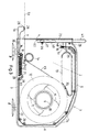
- Fig. 1 shows the housing 1 of the dispenser with a side wall 2, at the edges of a bottom wall 3, a front wall 4 oriented at right angles thereto, a top wall 5 and a rear wall 6 sit.
- the front wall 4 leaves an exit window 7 opposite the bottom wall 3.
- On the bottom wall 3 sit two suction feet 8.
- a hub 9 is formed, on which one Recording 10 with spiral arms 11 for an adhesive tape roll or masking tape roll 12 rotatably arranged is.
- a wall 13 extending through the housing 1 and enclosing a cutout is also included a guide section 35 is provided, the cutout of the wall 13 serving as a handle.
- a deflection guide or deflection roller 14 for the adhesive tape or Masking tape 15.
- a slide 16 between the bottom wall 3 and at least one guide pin 17 seated on the side wall 2 is arranged displaceably. Moreover are a pin 18 and a stop fork 19 with two parallel to the guide for the carriage 16 Bottom wall 3 aligned legs 20, 21 provided, compare in particular Fig. 1.
- a slot 30 of the carriage 16 engages over a pin 18 of the side wall 2 and through the slot ends End positions of the carriage 16 fixed.
- a drawstring 22 connects the carriage 16 to a slider 23 which carries a knife 52.
- the Drawstring 22 can be a wire, a rope, a thread, a strip-like band or the like.
- the Tension band 22 is via hollow pins or sleeves 24 seated on the side wall 2 and a curved guide 25 guided.
- the slider 23 is between the front wall 4 and hollow pin 26 and an oval guide pin 27 guided and parallel to the front wall 4 and thus in the plane of the exit window 7 displaceable.
- a slot 46 of the slider 23 engages over the hollow pin 26 and sets the end positions of the carriage 23 firmly.
- a housing cover 41 according to FIG. 2 fits into the end edge of the housing 1 by clamping or latching and engages with pins 42 or a profile wall 43 in the hollow pin 24 or in the curved guide 25 pinching or snapping.
- a conical or cylindrical and slotted sleeve 44, 45 engages in each Hub 9 for the adhesive tape roll 12 or into the hub of the deflection roller 14. The entire housing cover 41 closes the housing 1.
- the carriage 16 has, on the one hand, a cutting table 28, in the upper side of which is provided with corrugations a slot 29 is designed as a cutting guide.
- a slot 29 is designed as a cutting guide.
- the pull rod 32 extends between the legs 20, 21 of the Stop fork 19 through.
- a spring 34 which is plugged onto the pull rod 32 lies on the one hand on the contact surface 31 and on the other hand to the stop fork 19. The spring 34 thus clamps the slide 16 in 1, so that the cutting table 28 protrudes from the exit window 7.
- the slider 23 has profiles on an actuating lug 47 to prevent the fingers from sliding off to exclude the operator.
- the drawstring 22 is fastened to a handle 48 by the same passed through a passage 49 and completed by a head 50. If necessary, sits between the handle 48 and the head 50 a spring 51.
- the end position of the carriage 16 is by the Stop surface 31 set.
- the slider 23 with the knife 52 must then still over the actual Move the cutting stroke within the slot 29. This cutting stroke is due to the elasticity of the Drawstring 22 provided. In the case of an inelastic or rigid tension band 22, the Spring 51 the cutting stroke ready.
- the roll of adhesive tape 12 is inserted into the housing 1.
- the tape 15 is guided over the deflection roller 14 through the exit window 7 to the cutting table 28 and placed there so that the adhesive layer of the adhesive tape 15 on the corrugations of the cutting table 28 adheres.
- the housing cover 41 is put on and locked in place with the housing. A strip of tape 53 of the desired working length is pulled out.
- the slide 23 is moved in the direction of the bottom wall 3 pushed.
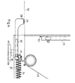
- the slide 16 is drawn into the interior of the housing and arrives via the drawstring 22 5, by the contact of the pin 17 at one end of the slot 30 is set.
- the knife 52 is immediately above the masking tape.
- the slider 23 is moved further over the cutting stroke, so that the knife 52 enters the slot 29 and cuts the masking tape, see FIG. 6.
- the spring 34 takes effect.
- the slider 23 and the carriage 16 return to the basic position under the action of the spring 34, so that the masking tape strip 53rd can be removed.
- the end of the masking tape 15 sticks to the cutting table 28.
Landscapes
- Adhesive Tape Dispensing Devices (AREA)
Abstract
Description
Claims (8)
- Abroller für Kreppband oder Klebeband, dessen Gehäuse eine Nabe für eine Klebebandrolle, Führungen für das Klebeband und ein Austrittsfenster für dasselbe aufweist, dadurch gekennzeichnet, daß in der Ebene des Austrittsfensters (7) ein Schieber (23) mit einem Messer (52) verschiebbar angeordnet ist, daß rechtwinklig zur Ebene des Austrittsfensters (7) ein Schlitten (16) mit einem Schneidtisch (28) verschiebbar angeordnet ist und daß der Schlitten (16) und der Schieber (23) durch Koppelmittel verbunden sind.
- Abroller nach Anspruch 1, dadurch gekennzeichnet, daß die Koppelmittel als Zugband (22) ausgebildet sind.
- Abroller nach Anspruch 1 oder 2, dadurch gekennzeichnet, daß der Schlitten (16) zwischen der Bodenwand (3) und mindestens einem Führungszapfen (17) geführt ist und daß ein Zapfen (18) der Seitenwand (2) zur Festlegung der Endlagen des Schlittens einen Schlitz (30) des Schlittens (16) durchgreift.
- Abroller nach Anspruch 3, dadurch gekennzeichnet, daß eine Zugstange (32), an die das Zugband (22) angehängt ist, durch eine Anschlaggabel (19) hindurchreicht..
- Abroller nach Anspruch 4, dadurch gekennzeichnet, daß auf der Zugstange (32) eine Feder (34) sitzt, die sich einerseits an einer Anlagefläche (31) des Schlittens (16) und andererseits an der Anschlaggabel (19) des Gehäuses (1) abstützt.
- Abroller nach einem der Ansprüche 3 bis 5, dadurch gekennzeichnet, daß der Schneidtisch (28) des Schlittens (16) einen Schlitz (29) aufweist, auf den in der Schneidstellung das Messer (52) des Schiebers (23) ausgerichtet ist.
- Abroller nach einem der Ansprüche 2 bis 5, dadurch gekennzeichnet, daß das Zugband (22) elastisch ausgebildet ist.
- Abroller nach einem der Ansprüche 2 bis 6, dadurch gekennzeichnet, daß das Zugband (22) unter Vermittlung einer Feder (51) mit dem Schieber (23) gekoppelt ist.
Applications Claiming Priority (2)
| Application Number | Priority Date | Filing Date | Title |
|---|---|---|---|
| DE2000131263 DE10031263C1 (de) | 2000-06-27 | 2000-06-27 | Abroller für Kreppband oder Klebeband |
| DE10031263 | 2000-06-27 |
Publications (2)
| Publication Number | Publication Date |
|---|---|
| EP1184318A2 true EP1184318A2 (de) | 2002-03-06 |
| EP1184318A3 EP1184318A3 (de) | 2004-05-12 |
Family
ID=7646962
Family Applications (1)
| Application Number | Title | Priority Date | Filing Date |
|---|---|---|---|
| EP01109554A Withdrawn EP1184318A3 (de) | 2000-06-27 | 2001-04-18 | Abroller für Kreppband oder Klebeband |
Country Status (2)
| Country | Link |
|---|---|
| EP (1) | EP1184318A3 (de) |
| DE (1) | DE10031263C1 (de) |
Family Cites Families (3)
| Publication number | Priority date | Publication date | Assignee | Title |
|---|---|---|---|---|
| JPS56140545U (de) * | 1980-03-19 | 1981-10-23 | ||
| US4630765A (en) * | 1985-05-22 | 1986-12-23 | Minnesota Minning And Manufacturing Company | Dispenser for tape with a stretchable backing |
| US5814184A (en) * | 1995-10-25 | 1998-09-29 | Denkins; Jeffrey L. | Hand operated mudless drywall tape applicator |
-
2000
- 2000-06-27 DE DE2000131263 patent/DE10031263C1/de not_active Expired - Fee Related
-
2001
- 2001-04-18 EP EP01109554A patent/EP1184318A3/de not_active Withdrawn
Also Published As
| Publication number | Publication date |
|---|---|
| DE10031263C1 (de) | 2001-07-05 |
| EP1184318A3 (de) | 2004-05-12 |
Similar Documents
| Publication | Publication Date | Title |
|---|---|---|
| DE69120932T2 (de) | Bandabroller | |
| DE4306312A1 (de) | ||
| EP0412489B1 (de) | Vorrichtung zum Schneiden von Obst, Gemüse oder dergleichen in Scheiben | |
| DE2332327C3 (de) | Vorrichtung zum Zuführen, Abtrennen und Anspülen des Fadenanfanges an eine laufende Spule | |
| DE3524758C2 (de) | ||
| DE2408201A1 (de) | Spann- und beschneidwerkzeug fuer ein um ein leiterbuendel gefuehrtes flexibles band | |
| EP0095599A2 (de) | Vorrichtung zum Zuführen eines Klebebandzuschnitts zu einem Gerät zum Verkleben des Rückens eines Buchblocks oder dergleichen | |
| DE10031263C1 (de) | Abroller für Kreppband oder Klebeband | |
| DE20018049U1 (de) | Splißschneidevorrichtung unter Verwendung elektrischer Haarschneidemaschinen | |
| DE202004011913U1 (de) | Messer mit einer Ausfahr- und Einzugseinrichtung für eine Klinge | |
| EP1854595B1 (de) | Abschneidevorrichtung mit einem Rastelement zum schrittweisen Bewegen eines Auswuchtgewichtsstrangs | |
| DE2433091A1 (de) | Hand-anleimgeraet mit fuehrungs- und kappeinrichtung | |
| DE3008739A1 (de) | Baenderzusammenklebmaschine, insbesondere fuer in kassetten zu ladende magnetbaender | |
| DE2320333A1 (de) | Vorrichtung zum schrittweisen abzug eines etikettenbandes | |
| DE19808538C2 (de) | Schneidvorrichtung und deren Verwendung | |
| DE19937140C2 (de) | Schneidmesser für Gipskartonplatten | |
| EP1493540B1 (de) | Papierschneidgerät | |
| DE2815912A1 (de) | Vorrichtung zum klemmbinden von zusammengetragenen papierblaettern | |
| DE19727198C2 (de) | Kleisterauftragsgerät für Tapetenbahnen | |
| DE2804620C3 (de) | Gummiband-Einziehgerät | |
| DE804796C (de) | Heftgeraet | |
| DE2755084B2 (de) | Papierführung in einer Schreibmaschine zur seitlichen Ausrichtung der Kante der Papierblätter | |
| DD94746B1 (de) | Fälzelstreifenabrollung | |
| DE7423445U (de) | Hand-Anleimgerät mit Führungsund Kappeinrichtung | |
| DE1511423A1 (de) | Klebstreifenausgeber |
Legal Events
| Date | Code | Title | Description |
|---|---|---|---|
| PUAI | Public reference made under article 153(3) epc to a published international application that has entered the european phase |
Free format text: ORIGINAL CODE: 0009012 |
|
| AK | Designated contracting states |
Kind code of ref document: A2 Designated state(s): AT BE CH CY DE DK ES FI FR GB GR IE IT LI LU MC NL PT SE TR |
|
| AX | Request for extension of the european patent |
Free format text: AL;LT;LV;MK;RO;SI |
|
| PUAL | Search report despatched |
Free format text: ORIGINAL CODE: 0009013 |
|
| AK | Designated contracting states |
Kind code of ref document: A3 Designated state(s): AT BE CH CY DE DK ES FI FR GB GR IE IT LI LU MC NL PT SE TR |
|
| AX | Request for extension of the european patent |
Extension state: AL LT LV MK RO SI |
|
| AKX | Designation fees paid | ||
| REG | Reference to a national code |
Ref country code: DE Ref legal event code: 8566 |
|
| STAA | Information on the status of an ep patent application or granted ep patent |
Free format text: STATUS: THE APPLICATION IS DEEMED TO BE WITHDRAWN |
|
| 18D | Application deemed to be withdrawn |
Effective date: 20041102 |