EP1183139B1 - Vorrichtung zum herstellen von kunststoff-formteilen - Google Patents
Vorrichtung zum herstellen von kunststoff-formteilen Download PDFInfo
- Publication number
- EP1183139B1 EP1183139B1 EP00934995A EP00934995A EP1183139B1 EP 1183139 B1 EP1183139 B1 EP 1183139B1 EP 00934995 A EP00934995 A EP 00934995A EP 00934995 A EP00934995 A EP 00934995A EP 1183139 B1 EP1183139 B1 EP 1183139B1
- Authority
- EP
- European Patent Office
- Prior art keywords
- container
- mould
- mold container
- axis
- supporting frame
- Prior art date
- Legal status (The legal status is an assumption and is not a legal conclusion. Google has not performed a legal analysis and makes no representation as to the accuracy of the status listed.)
- Expired - Lifetime
Links
Images
Classifications
-
- B—PERFORMING OPERATIONS; TRANSPORTING
- B29—WORKING OF PLASTICS; WORKING OF SUBSTANCES IN A PLASTIC STATE IN GENERAL
- B29C—SHAPING OR JOINING OF PLASTICS; SHAPING OF MATERIAL IN A PLASTIC STATE, NOT OTHERWISE PROVIDED FOR; AFTER-TREATMENT OF THE SHAPED PRODUCTS, e.g. REPAIRING
- B29C33/00—Moulds or cores; Details thereof or accessories therefor
- B29C33/0022—Multi-cavity moulds
-
- B—PERFORMING OPERATIONS; TRANSPORTING
- B29—WORKING OF PLASTICS; WORKING OF SUBSTANCES IN A PLASTIC STATE IN GENERAL
- B29C—SHAPING OR JOINING OF PLASTICS; SHAPING OF MATERIAL IN A PLASTIC STATE, NOT OTHERWISE PROVIDED FOR; AFTER-TREATMENT OF THE SHAPED PRODUCTS, e.g. REPAIRING
- B29C41/00—Shaping by coating a mould, core or other substrate, i.e. by depositing material and stripping-off the shaped article; Apparatus therefor
- B29C41/02—Shaping by coating a mould, core or other substrate, i.e. by depositing material and stripping-off the shaped article; Apparatus therefor for making articles of definite length, i.e. discrete articles
- B29C41/04—Rotational or centrifugal casting, i.e. coating the inside of a mould by rotating the mould
- B29C41/06—Rotational or centrifugal casting, i.e. coating the inside of a mould by rotating the mould about two or more axes
-
- B—PERFORMING OPERATIONS; TRANSPORTING
- B29—WORKING OF PLASTICS; WORKING OF SUBSTANCES IN A PLASTIC STATE IN GENERAL
- B29C—SHAPING OR JOINING OF PLASTICS; SHAPING OF MATERIAL IN A PLASTIC STATE, NOT OTHERWISE PROVIDED FOR; AFTER-TREATMENT OF THE SHAPED PRODUCTS, e.g. REPAIRING
- B29C41/00—Shaping by coating a mould, core or other substrate, i.e. by depositing material and stripping-off the shaped article; Apparatus therefor
- B29C41/34—Component parts, details or accessories; Auxiliary operations
- B29C41/52—Measuring, controlling or regulating
-
- B—PERFORMING OPERATIONS; TRANSPORTING
- B29—WORKING OF PLASTICS; WORKING OF SUBSTANCES IN A PLASTIC STATE IN GENERAL
- B29C—SHAPING OR JOINING OF PLASTICS; SHAPING OF MATERIAL IN A PLASTIC STATE, NOT OTHERWISE PROVIDED FOR; AFTER-TREATMENT OF THE SHAPED PRODUCTS, e.g. REPAIRING
- B29C41/00—Shaping by coating a mould, core or other substrate, i.e. by depositing material and stripping-off the shaped article; Apparatus therefor
- B29C41/02—Shaping by coating a mould, core or other substrate, i.e. by depositing material and stripping-off the shaped article; Apparatus therefor for making articles of definite length, i.e. discrete articles
- B29C41/18—Slush casting, i.e. pouring moulding material into a hollow mould with excess material being poured off
Definitions
- the invention relates to a device for producing Plastic molded parts, according to the preamble of claim 1.
- Devices of this type e.g. from EP-A1 0 502 378 for manufacturing of shaped films made of flake or powdered plastic materials are known by the mold melting process (slush process), contain a two-part from a powder box and one after the other heated and cooled molded shell existing mold container, the during the melting process to achieve a uniform Foil thickness and a high quality surface quality, especially at entangled spatial forms around two perpendicular axes rotated back and forth and additionally in the direction of one axis of rotation must be moved oscillating.
- the molding container linearly displaceable in a supporting frame, which in turn rotatable about the longitudinal axis via end bearings driven and with the help of individually controllable lifting cylinders which selectively raise and lower the bearing points together with the molded container about a pivot axis perpendicular to the longitudinal axis is tilted.
- Such pivoting kinematics is complicated, structurally complex construction, requires powerful lifting drives and has the further disadvantage that the pivoting movement of the molded container is only possible within a limited angular range, on a biaxial Fully rotatable suspension of the molded container, however, although procedurally desired, must be waived.
- the object of the invention is in a device of the aforementioned Kind in a structurally simple way and reducing the moving Masses a biaxially fully rotatable and oscillating in the direction of an axis to achieve movable storage of the molded container.
- the device according to the invention has due to the claimed Articulated connections via a structurally very simple, biaxially rotatable and at the same time linearly movable suspension of the molded container, whereby at the linear movements and the rotary movements around the swivel axis only the molded container, but not the support frame takes part, so that it moving masses and accordingly the loads of the associated Bearings and drives are kept low with the Another effect that can be easily with the device according to the invention an unrestricted rotatability of the molded container around both Axes can be realized.
- the rotary actuator and the linear actuator can be individually varied for the molded container and the rotary drive for the support frame expediently in each case independently of one another controllable.
- the molded container according to claim 3 two separate, symmetrical to the swivel axis Mold interiors, increasing the manufacturing capacity of the device is easily doubled.
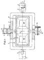
- the device for producing shaped films e.g. Dashboards of motor vehicles, of thermoplastic, flake or contains powdered plastic material by way of the slush process one that is flexibly suspended in three degrees of freedom and individual controllable molded container 2, which is mounted in a support frame 4, which via end bearings 6, 8 about a horizontal axis of rotation A rotatably supported and by means of a motor M in the direction of rotation (Direction of arrow I) is driven.
- a fully rotatable mounting of the molded container 2 about a second axis of rotation A vertical axis B, combined with a translationally limited Slidable suspension is laterally between each Mold container 2 and support frame 4 arranged rotary sliding joints 10, 12 causes, on the one hand, a linear drive in the form of a reversible hydraulic actuator 14 for an oscillating stroke movement in Arrow direction II and on the other hand a rotary drive 16 for a pivoting movement (Arrow direction III) of the molded container 2 with respect to the supporting frame 4 assigned.
- the drives 14, 16 and M are independent of one another controllable.
- the molded container 2 itself consists of an attached to an inner frame 18 Molding tool 20, which for reasons of increased manufacturing capacity two mold sections arranged symmetrically to the pivot axis B. 22A and 22B.
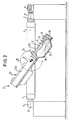
- Each mold section 22A, B contains one thin-walled, galvanoplastic molded shell 24 with one of the Contour of the molded part corresponding to the molded surface 26 (FIG. 2), which are fastened together with a detachable to the molded container 2
- Powder box 28 limits the mold interior 30.
- the mold 20 is double-walled, and the cavity 32 thus formed is on the back of the mold shell 24 with inlet and outlet ports 34, 36 for a cooling and heating medium, preferably Oil provided through which the mold surface 26 during the manufacturing process is heated and cooled alternately.
- a cooling and heating medium preferably Oil provided through which the mold surface 26 during the manufacturing process is heated and cooled alternately.
- the powder box 28 is first released and with the plastic material filled and then the mold interior 30 by the Powder box 28 closed, whereupon the mold container 2 is program-controlled around the two axes of rotation A and B several times in one and then rotated in the other direction and in the direction of the pivot axis B is oscillating back and forth.
- the on heated this way with plastic flakes sprinkled mold surface 26, so that the plastic material there in layers and with even Layer thickness melts.
Landscapes
- Engineering & Computer Science (AREA)
- Mechanical Engineering (AREA)
- Moulding By Coating Moulds (AREA)
- Vehicle Interior And Exterior Ornaments, Soundproofing, And Insulation (AREA)
- Extrusion Moulding Of Plastics Or The Like (AREA)
Description
- Fig. 1
- die Aufsicht einer Vorrichtung nach der Erfindung zum Herstellen von Formfolien aus thermoplastischem, flockenförmigem Kunststoffpulver nach dem Formaufschmelzverfahren; und
- Fig. 2
- eine teilweise geschnittene Seitenansicht der Vorrichtung nach Fig. 1.
Claims (3)
- Vorrichtung zum Herstellen von Kunststoff-Formteilen, insbesondere von Formfolien aus thermoplastischen Kunststoffflocken nach dem Slush-Verfahren, mit einem Formbehälter (2) mit mindestens einem mit dem Kunststoffmaterial befüllbaren Forminnenraum (30) einschließlich einer in wechselnder Abfolge heiz- und kühlbaren Formfläche (26) sowie mit einem um eine Rotationsachse (A) angetriebenen Tragrahmen (4) für den Formbehälter (2),
gekennzeichnet durch
eine kombinierte, zwischen Tragrahmen (4) und Formbehälter (2) wirksame Schwenk-Schiebeverbindung (10, 12), über die der Formbehälter am Tragrahmen um eine senkrecht zur Rotationsachse (A) des Tragrahmens verlaufende Schwenkachse (B) drehbar und in Richtung der Schwenkachse oszillierend beweglich gelagert ist. - Vorrichtung nach Anspruch 1,
dadurch gekennzeichnet, daß
der Schwenkantrieb (16) und der Linearantrieb (14) für den Formbehälter (2) sowie der Rotationsantrieb (M) für den Tragrahmen (4) jeweils unabhängig voneinander steuerbar sind. - Vorrichtung nach Anspruch 1 oder 2,
dadurch gekennzeichnet, daß
der Formbehälter (2) zwei voneinander getrennte, symmetrisch zur Schwenkachse (B) angeordnete Forminnenräume (30) enthält.
Applications Claiming Priority (3)
| Application Number | Priority Date | Filing Date | Title |
|---|---|---|---|
| DE19922164 | 1999-05-12 | ||
| DE19922164A DE19922164A1 (de) | 1999-05-12 | 1999-05-12 | Vorrichtung zum Herstellen von Kunststofformteilen |
| PCT/EP2000/004157 WO2000069611A2 (de) | 1999-05-12 | 2000-05-10 | Vorrichtung zum herstellen von kunststoff-formteilen |
Publications (2)
| Publication Number | Publication Date |
|---|---|
| EP1183139A2 EP1183139A2 (de) | 2002-03-06 |
| EP1183139B1 true EP1183139B1 (de) | 2002-10-30 |
Family
ID=7908008
Family Applications (1)
| Application Number | Title | Priority Date | Filing Date |
|---|---|---|---|
| EP00934995A Expired - Lifetime EP1183139B1 (de) | 1999-05-12 | 2000-05-10 | Vorrichtung zum herstellen von kunststoff-formteilen |
Country Status (7)
| Country | Link |
|---|---|
| US (1) | US6648625B2 (de) |
| EP (1) | EP1183139B1 (de) |
| JP (1) | JP2002544015A (de) |
| AT (1) | ATE226877T1 (de) |
| DE (2) | DE19922164A1 (de) |
| ES (1) | ES2185597T3 (de) |
| WO (1) | WO2000069611A2 (de) |
Families Citing this family (11)
| Publication number | Priority date | Publication date | Assignee | Title |
|---|---|---|---|---|
| DE10027201A1 (de) * | 2000-05-23 | 2001-11-29 | Volkswagen Ag | Laborversuchsanlage |
| DE102007019862B4 (de) | 2007-04-25 | 2009-05-14 | Peguform Gmbh | Form, Vorrichtung und Verfahren zur Herstellung von Formhäuten und Formkörpern aus Kunststoff |
| WO2009126948A2 (en) * | 2008-04-11 | 2009-10-15 | Linares Medical Devices, Llc | Mold and process for combining metal/ceramic and polymer component mixture in the formation of homogenous parts and further including an article of manufacture & process for creating a combination plastic and silver composite exhibiting lifelong anti-biotic properties |
| US8562333B2 (en) * | 2011-01-31 | 2013-10-22 | Konal Engineering And Equipment Inc. | Rotational molding machine and method |
| BE1020382A5 (nl) | 2012-04-30 | 2013-08-06 | Plastigi | Inrichting en werkwijze voor rotatiegieten van kunststof. |
| CN103395154A (zh) * | 2013-07-01 | 2013-11-20 | 长春富维—江森自控汽车饰件系统有限公司 | 搪塑表皮b面波纹的消除方法 |
| MX2020004480A (es) * | 2017-10-25 | 2020-08-03 | Univ Michigan Regents | Moldeo termico monolitico de mezclas de polimeros para aplicaciones arquitectonicas. |
| LU101869B1 (de) * | 2020-06-19 | 2021-12-20 | Roto Evolution Gmbh | Rotationsgussvorrichtung sowie Verfahren zum Betreiben einer Rotationsgussvorrichtung |
| WO2021255074A1 (de) * | 2020-06-19 | 2021-12-23 | Roto Evolution Gmbh | Rotationsgussvorrichtung sowie verfahren zum betreiben einer rotationsgussvorrichtung |
| CN114571646B (zh) * | 2022-02-14 | 2023-02-10 | 苏州恒坤精密电子有限公司 | 一种新能源电池绝缘材料制作成型系统及生产工艺 |
| CN115922982A (zh) * | 2022-12-09 | 2023-04-07 | 合肥大道模具有限责任公司 | 一种高精度、高强度pom模具的制作工艺 |
Family Cites Families (5)
| Publication number | Priority date | Publication date | Assignee | Title |
|---|---|---|---|---|
| US3337662A (en) * | 1963-10-10 | 1967-08-22 | Allied Chem | Process for cavity wetting |
| DE2160124A1 (de) * | 1971-01-08 | 1972-08-24 | Monster Molding Ltd | Verfahren zum Rotationspressen von Formkörpern bei Raumtemperatur |
| FR2590836B1 (fr) * | 1985-12-02 | 1988-04-15 | Luchaire Sa | Procede et machine de fabrication de pieces creuses en matiere plastique, par roulage par rotation |
| DE4106964C2 (de) | 1991-03-05 | 1994-07-21 | Peguform Werke Gmbh | Vorrichtung und Verfahren zum Herstellen von Formhäuten und -körpern aus Kunststoff |
| DE4142109C2 (de) * | 1991-12-19 | 1995-10-12 | Krauss Maffei Ag | Vorrichtung zum Herstellen von Kunststoff-Formfolien |
-
1999
- 1999-05-12 DE DE19922164A patent/DE19922164A1/de not_active Withdrawn
-
2000
- 2000-05-10 JP JP2000618058A patent/JP2002544015A/ja active Pending
- 2000-05-10 DE DE50000707T patent/DE50000707D1/de not_active Expired - Fee Related
- 2000-05-10 EP EP00934995A patent/EP1183139B1/de not_active Expired - Lifetime
- 2000-05-10 AT AT00934995T patent/ATE226877T1/de not_active IP Right Cessation
- 2000-05-10 WO PCT/EP2000/004157 patent/WO2000069611A2/de not_active Ceased
- 2000-05-10 ES ES00934995T patent/ES2185597T3/es not_active Expired - Lifetime
-
2001
- 2001-11-13 US US10/032,561 patent/US6648625B2/en not_active Expired - Fee Related
Also Published As
| Publication number | Publication date |
|---|---|
| ES2185597T3 (es) | 2003-05-01 |
| US20020051834A1 (en) | 2002-05-02 |
| DE19922164A1 (de) | 2000-11-16 |
| DE50000707D1 (de) | 2002-12-05 |
| EP1183139A2 (de) | 2002-03-06 |
| JP2002544015A (ja) | 2002-12-24 |
| US6648625B2 (en) | 2003-11-18 |
| WO2000069611A3 (de) | 2001-03-29 |
| ATE226877T1 (de) | 2002-11-15 |
| WO2000069611A2 (de) | 2000-11-23 |
Similar Documents
| Publication | Publication Date | Title |
|---|---|---|
| EP0502378B1 (de) | Vorrichtung und Verfahren zum Herstellen von Formhäuten und -körpern aus Kunststoff | |
| DE19747698C2 (de) | Blasformmaschine | |
| EP1979148B1 (de) | Transfersystem für mehrkomponenten spritzgiessen | |
| EP2173542B1 (de) | Befüllungseinrichtung zum befüllen von formwerkzeugen mit schüttfähigem formmaterial | |
| DE3635334A1 (de) | Verfahren und vorrichtung zur herstellung grossvolumiger hohlkoerper aus kunststoff mit mehrschichtigen wandungen | |
| EP2081758B1 (de) | Vorrichtung und verfahren zum bilden von formlingen aus einer formbaren masse | |
| WO2000069611A2 (de) | Vorrichtung zum herstellen von kunststoff-formteilen | |
| DE7441333U (de) | Rotationsmaschine mit entformungsvorrichtung | |
| WO2016202866A1 (de) | Puverbettbasiertes laserschmelzen-anlage | |
| EP0301200B1 (de) | Kunststoff-Spritzgiessmaschine für wahlweise zentrale oder lineare Formfüllung | |
| EP0572593B1 (de) | Vorrichtung zum herstellen von kunststoff-formfolien | |
| EP0566927B1 (de) | Verfahren und Vorrichtung zur Herstellung von Schokoladenartikeln | |
| EP3253549B1 (de) | Spritzgiessvorrichtung zum herstellen von teilen aus kunststoff | |
| DE19922684C2 (de) | Blasformmaschine für das abfallarme Blasen | |
| DE19531328C2 (de) | Spritzgießeinheit für eine Kunststoff-Spritzgießmaschine | |
| DE3033652A1 (de) | Verfahren und einrichtung zur herstellung und zum stapeln kastenloser formballen | |
| EP1385689B1 (de) | Extrusionskopf zur herstellung eines schlauch- oder rohrförmigen kunststoffstranges | |
| EP2081759B1 (de) | Hochleistungs-rotationsumlauf-form-verfahren und -vorrichtung | |
| EP1772247B1 (de) | Verfahren zur Herstellung von Kunststoff-Formhäuten | |
| DE10208053B3 (de) | Slush-Moulding-Anlage zur Herstellung einer Kunststoffhaut | |
| DE69628848T2 (de) | Mehrachsiges rotationsformverfahren und vorrichtung | |
| DE2401901A1 (de) | Schliesseinheit und verfahren fuer die herstellung von kunststoff-formteilen | |
| DE2004894A1 (en) | Several thermoplastic blowing moulds served by one extruder | |
| DE8629759U1 (de) | Vorrichtung zur Herstellung von Gegenständen aus thermoplastischem Kunststoff | |
| DE4242656A1 (de) | Vorrichtung zur Erzeugung eines Werkstücks aus einem thermisch erweichbaren Kunststoff in einer ortsfest angebrachten Form |
Legal Events
| Date | Code | Title | Description |
|---|---|---|---|
| PUAI | Public reference made under article 153(3) epc to a published international application that has entered the european phase |
Free format text: ORIGINAL CODE: 0009012 |
|
| 17P | Request for examination filed |
Effective date: 20011212 |
|
| AK | Designated contracting states |
Kind code of ref document: A2 Designated state(s): AT BE CH CY DE DK ES FI FR GB GR IE IT LI LU MC NL PT SE |
|
| AX | Request for extension of the european patent |
Free format text: AL;LT;LV;MK;RO;SI |
|
| GRAG | Despatch of communication of intention to grant |
Free format text: ORIGINAL CODE: EPIDOS AGRA |
|
| GRAG | Despatch of communication of intention to grant |
Free format text: ORIGINAL CODE: EPIDOS AGRA |
|
| GRAH | Despatch of communication of intention to grant a patent |
Free format text: ORIGINAL CODE: EPIDOS IGRA |
|
| 17Q | First examination report despatched |
Effective date: 20020426 |
|
| GRAH | Despatch of communication of intention to grant a patent |
Free format text: ORIGINAL CODE: EPIDOS IGRA |
|
| GRAA | (expected) grant |
Free format text: ORIGINAL CODE: 0009210 |
|
| AK | Designated contracting states |
Kind code of ref document: B1 Designated state(s): AT BE CH CY DE DK ES FI FR GB GR IE IT LI LU MC NL PT SE |
|
| PG25 | Lapsed in a contracting state [announced via postgrant information from national office to epo] |
Ref country code: NL Free format text: LAPSE BECAUSE OF FAILURE TO SUBMIT A TRANSLATION OF THE DESCRIPTION OR TO PAY THE FEE WITHIN THE PRESCRIBED TIME-LIMIT Effective date: 20021030 Ref country code: IE Free format text: LAPSE BECAUSE OF FAILURE TO SUBMIT A TRANSLATION OF THE DESCRIPTION OR TO PAY THE FEE WITHIN THE PRESCRIBED TIME-LIMIT Effective date: 20021030 Ref country code: GR Free format text: LAPSE BECAUSE OF FAILURE TO SUBMIT A TRANSLATION OF THE DESCRIPTION OR TO PAY THE FEE WITHIN THE PRESCRIBED TIME-LIMIT Effective date: 20021030 Ref country code: FI Free format text: LAPSE BECAUSE OF FAILURE TO SUBMIT A TRANSLATION OF THE DESCRIPTION OR TO PAY THE FEE WITHIN THE PRESCRIBED TIME-LIMIT Effective date: 20021030 |
|
| REF | Corresponds to: |
Ref document number: 226877 Country of ref document: AT Date of ref document: 20021115 Kind code of ref document: T |
|
| REG | Reference to a national code |
Ref country code: GB Ref legal event code: FG4D Free format text: NOT ENGLISH |
|
| REG | Reference to a national code |
Ref country code: CH Ref legal event code: EP |
|
| REG | Reference to a national code |
Ref country code: IE Ref legal event code: FG4D Free format text: GERMAN |
|
| REF | Corresponds to: |
Ref document number: 50000707 Country of ref document: DE Date of ref document: 20021205 |
|
| GBT | Gb: translation of ep patent filed (gb section 77(6)(a)/1977) |
Effective date: 20021202 |
|
| PG25 | Lapsed in a contracting state [announced via postgrant information from national office to epo] |
Ref country code: PT Free format text: LAPSE BECAUSE OF FAILURE TO SUBMIT A TRANSLATION OF THE DESCRIPTION OR TO PAY THE FEE WITHIN THE PRESCRIBED TIME-LIMIT Effective date: 20030130 Ref country code: DK Free format text: LAPSE BECAUSE OF FAILURE TO SUBMIT A TRANSLATION OF THE DESCRIPTION OR TO PAY THE FEE WITHIN THE PRESCRIBED TIME-LIMIT Effective date: 20030130 |
|
| ET | Fr: translation filed | ||
| NLV1 | Nl: lapsed or annulled due to failure to fulfill the requirements of art. 29p and 29m of the patents act | ||
| LTIE | Lt: invalidation of european patent or patent extension |
Effective date: 20021030 |
|
| REG | Reference to a national code |
Ref country code: ES Ref legal event code: FG2A Ref document number: 2185597 Country of ref document: ES Kind code of ref document: T3 |
|
| PG25 | Lapsed in a contracting state [announced via postgrant information from national office to epo] |
Ref country code: LU Free format text: LAPSE BECAUSE OF NON-PAYMENT OF DUE FEES Effective date: 20030510 Ref country code: CY Free format text: LAPSE BECAUSE OF FAILURE TO SUBMIT A TRANSLATION OF THE DESCRIPTION OR TO PAY THE FEE WITHIN THE PRESCRIBED TIME-LIMIT Effective date: 20030510 Ref country code: AT Free format text: LAPSE BECAUSE OF NON-PAYMENT OF DUE FEES Effective date: 20030510 |
|
| PG25 | Lapsed in a contracting state [announced via postgrant information from national office to epo] |
Ref country code: MC Free format text: LAPSE BECAUSE OF NON-PAYMENT OF DUE FEES Effective date: 20030531 |
|
| REG | Reference to a national code |
Ref country code: IE Ref legal event code: FD4D Ref document number: 1183139E Country of ref document: IE |
|
| PLBI | Opposition filed |
Free format text: ORIGINAL CODE: 0009260 |
|
| 26 | Opposition filed |
Opponent name: PEGUFORM GMBH & CO. KG Effective date: 20030626 |
|
| PLAX | Notice of opposition and request to file observation + time limit sent |
Free format text: ORIGINAL CODE: EPIDOSNOBS2 |
|
| PLBB | Reply of patent proprietor to notice(s) of opposition received |
Free format text: ORIGINAL CODE: EPIDOSNOBS3 |
|
| PG25 | Lapsed in a contracting state [announced via postgrant information from national office to epo] |
Ref country code: LI Free format text: LAPSE BECAUSE OF NON-PAYMENT OF DUE FEES Effective date: 20040531 Ref country code: CH Free format text: LAPSE BECAUSE OF NON-PAYMENT OF DUE FEES Effective date: 20040531 |
|
| PLCK | Communication despatched that opposition was rejected |
Free format text: ORIGINAL CODE: EPIDOSNREJ1 |
|
| REG | Reference to a national code |
Ref country code: CH Ref legal event code: PL |
|
| PLBN | Opposition rejected |
Free format text: ORIGINAL CODE: 0009273 |
|
| STAA | Information on the status of an ep patent application or granted ep patent |
Free format text: STATUS: OPPOSITION REJECTED |
|
| 27O | Opposition rejected |
Effective date: 20041005 |
|
| PGFP | Annual fee paid to national office [announced via postgrant information from national office to epo] |
Ref country code: DE Payment date: 20050419 Year of fee payment: 6 |
|
| PGFP | Annual fee paid to national office [announced via postgrant information from national office to epo] |
Ref country code: GB Payment date: 20050425 Year of fee payment: 6 |
|
| PGFP | Annual fee paid to national office [announced via postgrant information from national office to epo] |
Ref country code: ES Payment date: 20050509 Year of fee payment: 6 |
|
| PGFP | Annual fee paid to national office [announced via postgrant information from national office to epo] |
Ref country code: FR Payment date: 20050518 Year of fee payment: 6 |
|
| PGFP | Annual fee paid to national office [announced via postgrant information from national office to epo] |
Ref country code: SE Payment date: 20050519 Year of fee payment: 6 |
|
| PGFP | Annual fee paid to national office [announced via postgrant information from national office to epo] |
Ref country code: BE Payment date: 20050520 Year of fee payment: 6 |
|
| PG25 | Lapsed in a contracting state [announced via postgrant information from national office to epo] |
Ref country code: GB Free format text: LAPSE BECAUSE OF NON-PAYMENT OF DUE FEES Effective date: 20060510 |
|
| PG25 | Lapsed in a contracting state [announced via postgrant information from national office to epo] |
Ref country code: SE Free format text: LAPSE BECAUSE OF NON-PAYMENT OF DUE FEES Effective date: 20060511 Ref country code: ES Free format text: LAPSE BECAUSE OF NON-PAYMENT OF DUE FEES Effective date: 20060511 |
|
| PG25 | Lapsed in a contracting state [announced via postgrant information from national office to epo] |
Ref country code: BE Free format text: LAPSE BECAUSE OF NON-PAYMENT OF DUE FEES Effective date: 20060531 |
|
| PGFP | Annual fee paid to national office [announced via postgrant information from national office to epo] |
Ref country code: IT Payment date: 20060531 Year of fee payment: 7 |
|
| PG25 | Lapsed in a contracting state [announced via postgrant information from national office to epo] |
Ref country code: DE Free format text: LAPSE BECAUSE OF NON-PAYMENT OF DUE FEES Effective date: 20061201 |
|
| EUG | Se: european patent has lapsed | ||
| GBPC | Gb: european patent ceased through non-payment of renewal fee |
Effective date: 20060510 |
|
| REG | Reference to a national code |
Ref country code: FR Ref legal event code: ST Effective date: 20070131 |
|
| REG | Reference to a national code |
Ref country code: ES Ref legal event code: FD2A Effective date: 20060511 |
|
| BERE | Be: lapsed |
Owner name: *KRAUSS-MAFFEI KUNSTSTOFFTECHNIK G.M.B.H. Effective date: 20060531 |
|
| PG25 | Lapsed in a contracting state [announced via postgrant information from national office to epo] |
Ref country code: FR Free format text: LAPSE BECAUSE OF NON-PAYMENT OF DUE FEES Effective date: 20060531 |
|
| PG25 | Lapsed in a contracting state [announced via postgrant information from national office to epo] |
Ref country code: IT Free format text: LAPSE BECAUSE OF NON-PAYMENT OF DUE FEES Effective date: 20070510 |