EP1182413A1 - Vorrichtung und Verfahren zur Behandlung von Warenbahnen - Google Patents
Vorrichtung und Verfahren zur Behandlung von Warenbahnen Download PDFInfo
- Publication number
- EP1182413A1 EP1182413A1 EP01114365A EP01114365A EP1182413A1 EP 1182413 A1 EP1182413 A1 EP 1182413A1 EP 01114365 A EP01114365 A EP 01114365A EP 01114365 A EP01114365 A EP 01114365A EP 1182413 A1 EP1182413 A1 EP 1182413A1
- Authority
- EP
- European Patent Office
- Prior art keywords
- combustion air
- radiator
- fuel gas
- air fan
- speed
- Prior art date
- Legal status (The legal status is an assumption and is not a legal conclusion. Google has not performed a legal analysis and makes no representation as to the accuracy of the status listed.)
- Granted
Links
Images

Classifications
-
- F—MECHANICAL ENGINEERING; LIGHTING; HEATING; WEAPONS; BLASTING
- F26—DRYING
- F26B—DRYING SOLID MATERIALS OR OBJECTS BY REMOVING LIQUID THEREFROM
- F26B13/00—Machines and apparatus for drying fabrics, fibres, yarns, or other materials in long lengths, with progressive movement
- F26B13/10—Arrangements for feeding, heating or supporting materials; Controlling movement, tension or position of materials
-
- F—MECHANICAL ENGINEERING; LIGHTING; HEATING; WEAPONS; BLASTING
- F23—COMBUSTION APPARATUS; COMBUSTION PROCESSES
- F23D—BURNERS
- F23D14/00—Burners for combustion of a gas, e.g. of a gas stored under pressure as a liquid
- F23D14/46—Details
- F23D14/60—Devices for simultaneous control of gas and combustion air
-
- F—MECHANICAL ENGINEERING; LIGHTING; HEATING; WEAPONS; BLASTING
- F23—COMBUSTION APPARATUS; COMBUSTION PROCESSES
- F23D—BURNERS
- F23D14/00—Burners for combustion of a gas, e.g. of a gas stored under pressure as a liquid
- F23D14/46—Details
- F23D14/62—Mixing devices; Mixing tubes
- F23D14/64—Mixing devices; Mixing tubes with injectors
-
- F—MECHANICAL ENGINEERING; LIGHTING; HEATING; WEAPONS; BLASTING
- F23—COMBUSTION APPARATUS; COMBUSTION PROCESSES
- F23N—REGULATING OR CONTROLLING COMBUSTION
- F23N1/00—Regulating fuel supply
- F23N1/02—Regulating fuel supply conjointly with air supply
- F23N1/022—Regulating fuel supply conjointly with air supply using electronic means
-
- F—MECHANICAL ENGINEERING; LIGHTING; HEATING; WEAPONS; BLASTING
- F26—DRYING
- F26B—DRYING SOLID MATERIALS OR OBJECTS BY REMOVING LIQUID THEREFROM
- F26B3/00—Drying solid materials or objects by processes involving the application of heat
- F26B3/28—Drying solid materials or objects by processes involving the application of heat by radiation, e.g. from the sun
- F26B3/30—Drying solid materials or objects by processes involving the application of heat by radiation, e.g. from the sun from infrared-emitting elements
- F26B3/305—Drying solid materials or objects by processes involving the application of heat by radiation, e.g. from the sun from infrared-emitting elements the infrared radiation being generated by combustion or combustion gases
-
- F—MECHANICAL ENGINEERING; LIGHTING; HEATING; WEAPONS; BLASTING
- F23—COMBUSTION APPARATUS; COMBUSTION PROCESSES
- F23N—REGULATING OR CONTROLLING COMBUSTION
- F23N2225/00—Measuring
- F23N2225/04—Measuring pressure
-
- F—MECHANICAL ENGINEERING; LIGHTING; HEATING; WEAPONS; BLASTING
- F23—COMBUSTION APPARATUS; COMBUSTION PROCESSES
- F23N—REGULATING OR CONTROLLING COMBUSTION
- F23N2225/00—Measuring
- F23N2225/08—Measuring temperature
-
- F—MECHANICAL ENGINEERING; LIGHTING; HEATING; WEAPONS; BLASTING
- F23—COMBUSTION APPARATUS; COMBUSTION PROCESSES
- F23N—REGULATING OR CONTROLLING COMBUSTION
- F23N2233/00—Ventilators
- F23N2233/06—Ventilators at the air intake
- F23N2233/08—Ventilators at the air intake with variable speed
-
- F—MECHANICAL ENGINEERING; LIGHTING; HEATING; WEAPONS; BLASTING
- F23—COMBUSTION APPARATUS; COMBUSTION PROCESSES
- F23N—REGULATING OR CONTROLLING COMBUSTION
- F23N2235/00—Valves, nozzles or pumps
- F23N2235/12—Fuel valves
- F23N2235/16—Fuel valves variable flow or proportional valves
-
- F—MECHANICAL ENGINEERING; LIGHTING; HEATING; WEAPONS; BLASTING
- F23—COMBUSTION APPARATUS; COMBUSTION PROCESSES
- F23N—REGULATING OR CONTROLLING COMBUSTION
- F23N3/00—Regulating air supply or draught
- F23N3/08—Regulating air supply or draught by power-assisted systems
- F23N3/082—Regulating air supply or draught by power-assisted systems using electronic means
Definitions
- the invention relates to a device and a method for the treatment of webs, in particular of textile webs, with at least one IR emitter, the IR radiator with a combustion air fan and fuel gas supply means and controllable in its heating capacity via a control device is.
- Such devices are particularly used for drying webs.
- the amount of fuel gas is known from practice controlled by a temperature controller. Dependent on the amount of fuel gas is then the required Combustion air through another control loop customized. The quantity is usually metered by throttle valves controlled by motors become. For the ignition of the IR emitter is also a separate facility is necessary.
- the invention is based on the object, the device according to claim 1 or the method according to claim 7 simplify and operational security too increase.
- the inventive device for treating webs has at least one IR radiator, wherein the IR radiator with a combustion air fan and fuel gas supply means in connection and via a control device in its heating capacity controllable is.
- the combustion air fan is in his Speed adjustable and stands with the control device in such a way that the speed to a desired Heating power can be adjusted.
- the Fuel gas supply means a pressure regulator, which the Amount of fuel gas depending on the combustion air fan generated air pressure regulates.
- the Fuel gas supply means a pressure regulator, which the Amount of fuel gas depending on the combustion air fan generated air pressure regulates.
- the Fuel gas supply can thus be completely motor-driven Throttle valves for metering the combustion air or the fuel gas can be dispensed with.
- IR emitters for example Ceramic emitters used, they glow due to their relatively large mass relative long after, causing damage to the web can. To protect the web in such cases, has therefore developed constructions in which the IR radiators can be swung away.
- Another known solution provides that between the web and IR illuminator is pulled up a protective curtain. such
- protective measures are relatively complex.
- the cooling time of the IR radiator compared to ceramic emitters considerably shorten because the ceramic spotlights due to their high Need a slightly longer cooling time.
- the combustion air fan is expedient via a frequency converter from the control device controlled to change the speed.
- the control device can with a temperature and / or humidity sensor related to the heat output of the IR radiator by changing the speed of the Combustion air fan to a desired value adapt.
- the frequency converter is used to ignite the IR radiator a certain speed of the combustion air fan driven. This can always be done with a exactly defined heating output can be started. A separate ignition bypass circuit is therefore not necessary.
- the control device in connection with the temperature and / or humidity sensor released so that the temperature or Moisture automatically to the preselected setpoint can be driven.
- the frequency converter limits the minimum and maximum fan speed. Thereby the minimum and maximum heating output of the IR radiator limited. Within this speed range continuous power control is guaranteed.
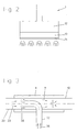
- the device shown in Figure 1 in a block diagram for the treatment of webs in particular points one or more IR radiators 1, a combustion air fan 2, fuel gas supply means 3 and a control device 4.
- the IR emitter 1 stands with the combustion air fan 2 and the fuel gas supply means 3 in conjunction with the control device 4 the speed of the combustion air fan 2 can be changed so that the speed to a desired Heating power can be adjusted.
- the IR radiators 1 are on one or both sides of a web 5, in particular one textile web, arranged.
- the web 5 is relative to the IR emitters 1 transported.
- the IR emitters 1 transported.
- the IR emitters 1 are two IR emitters above the web 5 shown.
- dashed lines are two further spotlights indicated on the underside. The number the arranged in and across the transport direction IR emitter depends on the respective requirements.
- a temperature and / or moisture sensor 6 In the area of the web or somewhere in the area of Exhaust air path of the device is a temperature and / or moisture sensor 6 is provided, its output signal the control device 4 is supplied.
- the Control device 4 controls a frequency converter 7 the speed of the combustion air fan 2 in order depending on the signal of the temperature and / or Moisture sensor 6 the heating power of the IR radiator 1 to adapt to a desired heating output.
- the fuel gas supply means 3 have in particular one Pressure regulator 30, which depends on the amount of fuel gas of the combustion air fan 2 generated Combustion air pressure regulates.
- the pressure regulator 30 stands thus via a sensing line 31 with the combustion air line 20 in connection.
- the pressure regulator 30 doses thus automatically the pressure of the fuel gas in the Fuel gas line 32.
- the desired ratio of combustion air pressure to fuel gas pressure can be on the pressure regulator set manually or electrically.
- the fuel gas supply means naturally have more known devices, such as solenoid valves 33, pressure indicators 34, pressure switch 35, another Pressure regulator 36 and a gas flow meter 37 on.
- a mixer 8 is provided in which the combustion air mixed with the fuel gas to form a gas-air mixture becomes.
- the mixer 8 can in particular be used as a DC mixer or countercurrent mixer.
- the mixer 8 designed as a counterflow mixer. Is on the input side the mixer 8 via the combustion air line 20 the combustion air fan 2 and via the fuel gas line 32 connected to the fuel gas supply means 3.
- the fuel gas line 32 thus opens into the combustion air line 20 a that the fuel gas 38 in countercurrent introduced to the combustion air 23 and with this is mixed to the gas-air mixture 11.
- the mixture in Counterflow mixer has compared to the DC mixer higher flow losses, however, is essential more intense, so that an evenly mixed gas-air mixture 11 arises. This in turn leads to a better and more even combustion.
- the gas-air mixture 11 is via the gas-air mixture lines 10 fed to the IR radiators 1.
- the IR radiators 1 can be used, for example, as ceramic radiators be trained. Leave particularly advantageous however, use IR radiators in the context of the invention, whose radiator surface consists of a metal mesh.
- a radiator is shown schematically in Fig.2 shown. It essentially consists of a distribution chamber 12 and a metal mesh 13, for example on a support grid, not shown is spanned.
- the metal mesh 13 can for example formed by a sintered metal mesh become.
- the actual firing zone 14 takes place on the outer Surface or inside of the metal mesh 13 instead of.
- the heat transfer can depend on the type of Firing conditions are done by radiation or convection.
- the control device 4 released so that the heating power automatically moved to the specified setpoint becomes. Via the signal from the temperature and / or humidity sensor 6, the control device 4, the heating power by changing the speed to a desired one Maintain level.
Landscapes
- Engineering & Computer Science (AREA)
- Chemical & Material Sciences (AREA)
- Combustion & Propulsion (AREA)
- Mechanical Engineering (AREA)
- General Engineering & Computer Science (AREA)
- Microbiology (AREA)
- Life Sciences & Earth Sciences (AREA)
- Textile Engineering (AREA)
- Drying Of Solid Materials (AREA)
- Treatment Of Fiber Materials (AREA)
- Regulation And Control Of Combustion (AREA)
- Treatments Of Macromolecular Shaped Articles (AREA)
- Treatments For Attaching Organic Compounds To Fibrous Goods (AREA)
Abstract
Description
- Fig.1
- ein Blockschaltbild der erfindungsgemäßen Vorrichtung,
- Fig.2
- eine schematische Darstellung des IR-Strahlers und
- Fig.3
- eine schematische Darstellung des Mischers.
Claims (10)
- Vorrichtung zur Behandlung von Warenbahnen mit wenigstens einem IR-Strahler (1), wobei der IR-Strahler mit einem Verbrennungsluftventilator (2) und Brenngaszuführmitteln (3) in Verbindung steht und über eine Regeleinrichtung (4) in seiner Heizleistung steuerbar ist,
dadurch gekennzeichnet, daß der Verbrennungsluftventilator (2) in seiner Drehzahl regelbar ist und mit der Regeleinrichtung (4) derart in Verbindung steht, daß die Drehzahl an eine gewünschte Heizleistung angepaßt werden kann. - Vorrichtung nach Anspruch 1, dadurch gekennzeichnet, daß die Brenngaszuführmittel (3) einen Druckregler (30) aufweisen, der die Brenngasmenge in Abhängigkeit des vom Verbrennungsluftventilators (2) erzeugten Verbrennungsluftdrucks regelt.
- Vorrichtung nach Anspruch 1, dadurch gekennzeichnet, daß der IR-Strahler (1) eine Strahlerfläche aus einem Metallgewebe (13) aufweist.
- Vorrichtung nach Anspruch 1, dadurch gekennzeichnet, daß ein Gegenstrommischer (8) vorgesehen ist, der eingangsseitig mit dem Verbrennungsluftventilator (2) und den Brenngaszuführmitteln (3) und ausgangsseitig mit dem IR-Strahler (1) in Verbindung steht, wobei das Brenngas (38) mit der Verbrennungsluft (23) im Gegenstrom zu einem Gas-Luftgemisch (11) zusammengeführt wird.
- Vorrichtung nach Anspruch 1, dadurch gekennzeichnet, daß die Regeleinrichtung (4) zur Veränderung der Heizleistung des IR-Strahlers (1) mit einem Temperatur- und/oder Feuchtigkeitssensor (6) in Verbindung steht.
- Vorrichtung nach Anspruch 1, dadurch gekennzeichnet, daß der Verbrennungsluftventilator (2) zur Veränderung der Drehzahl mit einem Frequenzumrichter (7) in Verbindung steht, der über die Regeleinrichtung (4) ansteuerbar ist.
- Verfahren zur Behandlung von Warenbahnen mit wenigstens einem IR-Strahler (1), wobei ein Verbrennungsluftventilator (2) eine Verbrennungsluftmenge erzeugt, die mit einer dosierten Brenngasmenge vermischt und dem IR-Strahler (1) zugeführt wird, wobei die Heizleistung des IR-Strahlers steuerbar ist,
dadurch gekennzeichnet, daß zur Veränderung der Heizleistung die Drehzahl des Verbrennungsluftventilators (2) verändert wird. - Verfahren nach Anspruch 7, dadurch gekennzeichnet, daß die Brenngasmenge in Abhängigkeit des Verbrennungsluftdrucks dosiert wird.
- Verfahren nach Anspruch 7, dadurch gekennzeichnet, daß beim Abschalten des IR-Strahlers (1) der Verbrennungsluftventilator (2) auf seine höchste Drehzahl geregelt wird, um eine sofortige Abkühlung des Strahlers zu bewirken.
- Verfahren nach Anspruch 7, dadurch gekennzeichnet, daß die Drehzahl des Verbrennungsluftventilators (2) in Abhängigkeit eines Temperatur- und/oder Feuchtigkeitssignals geregelt wird.
Applications Claiming Priority (2)
| Application Number | Priority Date | Filing Date | Title |
|---|---|---|---|
| DE10040788A DE10040788A1 (de) | 2000-08-21 | 2000-08-21 | Vorrichtung und Verfahren zur Behandlung von Warenbahnen |
| DE10040788 | 2000-08-21 |
Publications (2)
| Publication Number | Publication Date |
|---|---|
| EP1182413A1 true EP1182413A1 (de) | 2002-02-27 |
| EP1182413B1 EP1182413B1 (de) | 2005-04-20 |
Family
ID=7653125
Family Applications (1)
| Application Number | Title | Priority Date | Filing Date |
|---|---|---|---|
| EP01114365A Expired - Lifetime EP1182413B1 (de) | 2000-08-21 | 2001-06-13 | Verfahren zur Behandlung von Warenbahnen |
Country Status (3)
| Country | Link |
|---|---|
| EP (1) | EP1182413B1 (de) |
| AT (1) | ATE293780T1 (de) |
| DE (2) | DE10040788A1 (de) |
Cited By (6)
| Publication number | Priority date | Publication date | Assignee | Title |
|---|---|---|---|---|
| WO2004006036A3 (en) * | 2002-07-05 | 2004-03-18 | Seco Warwick Sp Z O O | Temperature control system |
| GB2419181A (en) * | 2004-10-12 | 2006-04-19 | Lg Electronics Inc | Gas burner and speed control of air supply fan |
| EP1650517A3 (de) * | 2004-10-19 | 2009-06-17 | Moretto S.p.A. | Adsorptionstrockner für Kunststoffgranulat. |
| US8046934B2 (en) * | 2006-01-25 | 2011-11-01 | Nv Bekaert Sa | Convective system for a dryer installation |
| CN102679356A (zh) * | 2011-03-15 | 2012-09-19 | 佛山市启迪节能科技有限公司 | 一种预混式二次燃烧器的自动控制方式及其装置 |
| CN103234218A (zh) * | 2013-04-23 | 2013-08-07 | 台州英达机械科技有限公司 | 喷灯的燃料输送装置 |
Families Citing this family (2)
| Publication number | Priority date | Publication date | Assignee | Title |
|---|---|---|---|---|
| CN101375123B (zh) * | 2006-01-25 | 2011-06-08 | 贝卡尔特股份有限公司 | 火焰干燥器 |
| DE102022212826A1 (de) * | 2022-11-29 | 2024-05-29 | Continental Reifen Deutschland Gmbh | Trocknungsvorrichtung |
Citations (5)
| Publication number | Priority date | Publication date | Assignee | Title |
|---|---|---|---|---|
| CH361271A (de) * | 1957-04-20 | 1962-04-15 | Belge Produits Chimiques Sa | Einrichtung zum Vermischen von Gasen |
| US3150864A (en) * | 1962-08-09 | 1964-09-29 | Gas Heat Engineering Corp | Apparatus for applying heat treatment to web material |
| US3228113A (en) * | 1960-08-18 | 1966-01-11 | John J Fannon Products Co | Heating apparatus and method |
| EP0317178A1 (de) * | 1987-11-19 | 1989-05-24 | Davair Heating Limited | Gasbrenner |
| EP0890791A1 (de) * | 1997-07-11 | 1999-01-13 | Electrowatt Technology Innovation AG | Steuer- und Regelgerät für einen Brenner |
Family Cites Families (1)
| Publication number | Priority date | Publication date | Assignee | Title |
|---|---|---|---|---|
| DE8817120U1 (de) * | 1988-04-07 | 1993-02-04 | Vits Maschinenbau Gmbh, 4018 Langenfeld | Vorrichtung zur Wärmebehandlung und/oder Trocknung einer Materialbahn |
-
2000
- 2000-08-21 DE DE10040788A patent/DE10040788A1/de not_active Ceased
-
2001
- 2001-06-13 DE DE50105941T patent/DE50105941D1/de not_active Expired - Fee Related
- 2001-06-13 EP EP01114365A patent/EP1182413B1/de not_active Expired - Lifetime
- 2001-06-13 AT AT01114365T patent/ATE293780T1/de not_active IP Right Cessation
Patent Citations (5)
| Publication number | Priority date | Publication date | Assignee | Title |
|---|---|---|---|---|
| CH361271A (de) * | 1957-04-20 | 1962-04-15 | Belge Produits Chimiques Sa | Einrichtung zum Vermischen von Gasen |
| US3228113A (en) * | 1960-08-18 | 1966-01-11 | John J Fannon Products Co | Heating apparatus and method |
| US3150864A (en) * | 1962-08-09 | 1964-09-29 | Gas Heat Engineering Corp | Apparatus for applying heat treatment to web material |
| EP0317178A1 (de) * | 1987-11-19 | 1989-05-24 | Davair Heating Limited | Gasbrenner |
| EP0890791A1 (de) * | 1997-07-11 | 1999-01-13 | Electrowatt Technology Innovation AG | Steuer- und Regelgerät für einen Brenner |
Cited By (8)
| Publication number | Priority date | Publication date | Assignee | Title |
|---|---|---|---|---|
| WO2004006036A3 (en) * | 2002-07-05 | 2004-03-18 | Seco Warwick Sp Z O O | Temperature control system |
| US7193188B2 (en) | 2002-07-05 | 2007-03-20 | Seco/Warwick Sp.Zo.O | Temperature control system for controlling heat treatment of metals, that is heating, soaking and cooling by a single frequency converter |
| GB2419181A (en) * | 2004-10-12 | 2006-04-19 | Lg Electronics Inc | Gas burner and speed control of air supply fan |
| GB2419181B (en) * | 2004-10-12 | 2008-01-09 | Lg Electronics Inc | Cooking Gas Burner and Method for Controlling the Same |
| EP1650517A3 (de) * | 2004-10-19 | 2009-06-17 | Moretto S.p.A. | Adsorptionstrockner für Kunststoffgranulat. |
| US8046934B2 (en) * | 2006-01-25 | 2011-11-01 | Nv Bekaert Sa | Convective system for a dryer installation |
| CN102679356A (zh) * | 2011-03-15 | 2012-09-19 | 佛山市启迪节能科技有限公司 | 一种预混式二次燃烧器的自动控制方式及其装置 |
| CN103234218A (zh) * | 2013-04-23 | 2013-08-07 | 台州英达机械科技有限公司 | 喷灯的燃料输送装置 |
Also Published As
| Publication number | Publication date |
|---|---|
| DE50105941D1 (de) | 2005-05-25 |
| EP1182413B1 (de) | 2005-04-20 |
| ATE293780T1 (de) | 2005-05-15 |
| DE10040788A1 (de) | 2002-03-07 |
Similar Documents
| Publication | Publication Date | Title |
|---|---|---|
| DE3312704C2 (de) | Trocknungsvorrichtung für eine Druckmaschine, mit Abgasrückführung von einer Oxidations- und Vorheizeinrichtung | |
| EP2594848B1 (de) | Verfahren zur Steuerung einer Feuerungseinrichtung und Feuerungseinrichtung | |
| DE69331081T2 (de) | Verfahren und Vorrichtung zum Mischen von Gasen | |
| DE19627539A1 (de) | Verfahren und Vorrichtung zum Steuern der Flammengröße gasbetriebener Koch- oder Backgeräte | |
| DE3441475A1 (de) | Verfahren zur steuerung eines heisslufterzeugers fuer einen kessel mit kohlefeuerung | |
| DE3638410C2 (de) | ||
| DE3639172C2 (de) | ||
| DE10148548C5 (de) | Backofen | |
| DE4236785A1 (de) | ||
| EP0006163B1 (de) | Verfahren und Vorrichtungen zur Rauchgasführung in einem Wärmekessel | |
| WO1987004773A1 (fr) | Procede d'exploitation d'un radiateur au gaz de rayons infra-rouges et radiateur au gaz de rayons infra-rouges | |
| EP1182413B1 (de) | Verfahren zur Behandlung von Warenbahnen | |
| EP1630361B1 (de) | Einrichtung und Verfahren zum Kühlen eines Gehäuses einer Gasturbine bzw. einer Brennkammer | |
| DE3025831C2 (de) | ||
| DE3027753A1 (de) | Verbrennungsvorrichtung, insbesondere zur durchfuehrung des thermischen regenerativverfahrens | |
| DE202004021534U1 (de) | Heizsystem für ein Fahrzeug | |
| EP0053269A2 (de) | Vorrichtung zur Wärmebehandlung von bahnförmigem Gut | |
| DE2949720A1 (de) | Verfahren und vorrichtung zum trocknen und erhitzen von feuchter kohle | |
| DE1408990C3 (de) | Vorrichtung zur Regelung des durch die Klinkerkühlanlage vorgewärmten Unterwindes bei Zementdrehrohröfen | |
| DE2825500C3 (de) | Verfahren und Einrichtung zur Mischung zweier Gasströme | |
| DE2119006A1 (de) | Verfahren und Vorrichtung zum Kühlen von in einem Ofensystem gebranntem Material, insbesondere von Zementklinker | |
| EP0178401A2 (de) | Verfahren zur Anpassung eines Tunnelofens an unterschiedliche Leistungen sowie rechnergeführter Tunnelofen | |
| DE4418885A1 (de) | Rostkühler für Brenngut und Verfahren zum Betrieb desselben | |
| DE102004063992B4 (de) | Verfahren zur Steuerung einer Feuerungseinrichtung und Feuerungseinrichtung | |
| DE1471921B2 (de) |
Legal Events
| Date | Code | Title | Description |
|---|---|---|---|
| PUAI | Public reference made under article 153(3) epc to a published international application that has entered the european phase |
Free format text: ORIGINAL CODE: 0009012 |
|
| AK | Designated contracting states |
Kind code of ref document: A1 Designated state(s): AT BE CH CY DE DK ES FI FR GB GR IE IT LI LU MC NL PT SE TR |
|
| AX | Request for extension of the european patent |
Free format text: AL;LT;LV;MK;RO;SI |
|
| 17P | Request for examination filed |
Effective date: 20020417 |
|
| AKX | Designation fees paid |
Free format text: AT CH DE IT LI |
|
| 17Q | First examination report despatched |
Effective date: 20021106 |
|
| GRAP | Despatch of communication of intention to grant a patent |
Free format text: ORIGINAL CODE: EPIDOSNIGR1 |
|
| RTI1 | Title (correction) |
Free format text: PROCESS FOR TREATMENT OF MATERIAL WEBS |
|
| GRAS | Grant fee paid |
Free format text: ORIGINAL CODE: EPIDOSNIGR3 |
|
| GRAA | (expected) grant |
Free format text: ORIGINAL CODE: 0009210 |
|
| AK | Designated contracting states |
Kind code of ref document: B1 Designated state(s): AT CH DE IT LI |
|
| REG | Reference to a national code |
Ref country code: CH Ref legal event code: EP |
|
| REG | Reference to a national code |
Ref country code: CH Ref legal event code: NV Representative=s name: RIEDERER HASLER & PARTNER PATENTANWAELTE AG |
|
| REG | Reference to a national code |
Ref country code: IE Ref legal event code: FG4D Free format text: LANGUAGE OF EP DOCUMENT: GERMAN |
|
| REF | Corresponds to: |
Ref document number: 50105941 Country of ref document: DE Date of ref document: 20050525 Kind code of ref document: P |
|
| PLBI | Opposition filed |
Free format text: ORIGINAL CODE: 0009260 |
|
| PLAX | Notice of opposition and request to file observation + time limit sent |
Free format text: ORIGINAL CODE: EPIDOSNOBS2 |
|
| 26 | Opposition filed |
Opponent name: MOENUS TEXTILMASCHINEN GMBH Effective date: 20060119 |
|
| PLBB | Reply of patent proprietor to notice(s) of opposition received |
Free format text: ORIGINAL CODE: EPIDOSNOBS3 |
|
| PGFP | Annual fee paid to national office [announced via postgrant information from national office to epo] |
Ref country code: AT Payment date: 20090615 Year of fee payment: 9 Ref country code: IT Payment date: 20090626 Year of fee payment: 9 |
|
| PGFP | Annual fee paid to national office [announced via postgrant information from national office to epo] |
Ref country code: CH Payment date: 20090617 Year of fee payment: 9 |
|
| PLAB | Opposition data, opponent's data or that of the opponent's representative modified |
Free format text: ORIGINAL CODE: 0009299OPPO |
|
| PGFP | Annual fee paid to national office [announced via postgrant information from national office to epo] |
Ref country code: DE Payment date: 20090828 Year of fee payment: 9 |
|
| R26 | Opposition filed (corrected) |
Opponent name: MOENUS TEXTILMASCHINEN GMBH Effective date: 20060119 |
|
| PLCK | Communication despatched that opposition was rejected |
Free format text: ORIGINAL CODE: EPIDOSNREJ1 |
|
| PLBN | Opposition rejected |
Free format text: ORIGINAL CODE: 0009273 |
|
| STAA | Information on the status of an ep patent application or granted ep patent |
Free format text: STATUS: OPPOSITION REJECTED |
|
| 27O | Opposition rejected |
Effective date: 20100522 |
|
| REG | Reference to a national code |
Ref country code: CH Ref legal event code: PL |
|
| PG25 | Lapsed in a contracting state [announced via postgrant information from national office to epo] |
Ref country code: IT Free format text: LAPSE BECAUSE OF NON-PAYMENT OF DUE FEES Effective date: 20100613 |
|
| PG25 | Lapsed in a contracting state [announced via postgrant information from national office to epo] |
Ref country code: DE Free format text: LAPSE BECAUSE OF NON-PAYMENT OF DUE FEES Effective date: 20110101 Ref country code: CH Free format text: LAPSE BECAUSE OF NON-PAYMENT OF DUE FEES Effective date: 20100630 Ref country code: LI Free format text: LAPSE BECAUSE OF NON-PAYMENT OF DUE FEES Effective date: 20100630 |
|
| PG25 | Lapsed in a contracting state [announced via postgrant information from national office to epo] |
Ref country code: AT Free format text: LAPSE BECAUSE OF NON-PAYMENT OF DUE FEES Effective date: 20100613 |