EP1180837B1 - Gehäuse für Elektroinstallationseinrichtungen - Google Patents
Gehäuse für Elektroinstallationseinrichtungen Download PDFInfo
- Publication number
- EP1180837B1 EP1180837B1 EP01118078A EP01118078A EP1180837B1 EP 1180837 B1 EP1180837 B1 EP 1180837B1 EP 01118078 A EP01118078 A EP 01118078A EP 01118078 A EP01118078 A EP 01118078A EP 1180837 B1 EP1180837 B1 EP 1180837B1
- Authority
- EP
- European Patent Office
- Prior art keywords
- housing
- hollow profile
- wall
- housing according
- profile
- Prior art date
- Legal status (The legal status is an assumption and is not a legal conclusion. Google has not performed a legal analysis and makes no representation as to the accuracy of the status listed.)
- Expired - Lifetime
Links
Images




Classifications
-
- H—ELECTRICITY
- H02—GENERATION; CONVERSION OR DISTRIBUTION OF ELECTRIC POWER
- H02B—BOARDS, SUBSTATIONS OR SWITCHING ARRANGEMENTS FOR THE SUPPLY OR DISTRIBUTION OF ELECTRIC POWER
- H02B1/00—Frameworks, boards, panels, desks, casings; Details of substations or switching arrangements
- H02B1/26—Casings; Parts thereof or accessories therefor
- H02B1/40—Wall-mounted casings; Parts thereof or accessories therefor
-
- H—ELECTRICITY
- H02—GENERATION; CONVERSION OR DISTRIBUTION OF ELECTRIC POWER
- H02B—BOARDS, SUBSTATIONS OR SWITCHING ARRANGEMENTS FOR THE SUPPLY OR DISTRIBUTION OF ELECTRIC POWER
- H02B1/00—Frameworks, boards, panels, desks, casings; Details of substations or switching arrangements
- H02B1/015—Boards, panels, desks; Parts thereof or accessories therefor
Definitions
- the invention relates to a housing for electrical installation equipment, in particular for distributors, meter stations and the like, which has a housing connected to the housing, the housing stabilizing hollow profile.
- the legs of the angle pieces are each secured in the cavity of a hollow profile plate.
- the EP-A-0008051 describes a device cover, which is assembled from profile parts, each forming an edge of the cover, plug-in corner connectors and a cover plate.
- the present invention has for its object to provide a housing for electrical installation equipment of the type mentioned above, which has an increased stability.
- the problem-solving housing according to the invention is characterized in that the hollow profile with its profile walls in one piece continuously extends around at least one corner of the housing.
- the hollow profiles can be produced using the known GID method, in which the workpiece is subjected in the injection mold before the complete solidification of an internal gas pressure.
- Such, e.g. integrally formed in a housing wall integrally with the housing hollow profile can give the housing even with a small wall thickness high strength.
- relatively little material is needed even for the hollow profile itself compared to stiffeners, which are formed as stiffening ribs by mere thickening of the housing wall, relatively little.
- stiffeners which are formed as stiffening ribs by mere thickening of the housing wall, relatively little.
- a hollow profile material accumulation which involves the risk of the formation of sink marks on the housing surface in itself, which can greatly affect the appearance of such a plastic housing.
- the hollow profile extends at least in sections along the edge of a housing wall, wherein it is in particular directly adjacent to the edge of the housing wall and preferably rotates like a frame around the housing wall.
- a housing wall e.g. formed on the front wall of a distributor housing cover or the rear wall of a distributor housing frame hollow profile can provide a high torsional stiffness of the housing parts and affects even if it extends in cross-section into the housing interior, due to its arrangement on the housing wall edge hardly the installation of electrical equipment in the housing usable mounting space.
- the hollow profile can also extend from the housing to the outside, so that inside the housing assembly space is lost at any point.
- the hollow profile is integrated into a housing wall such that it is formed over part of its circumference by the housing wall itself.
- the hollow profile may be formed in the corner region of angularly adjacent housing walls, e.g. in the corner region between a housing rear wall and the housing side walls, wherein the hollow profile is formed by the angularly abutting housing walls and a peripheral portion connecting the housing walls.
- Such a peripheral portion may be bent to form a three-cornered hollow profile straight or according to a circular line.
- Such a peripheral portion of the hollow profile then forms a Eckenabschrägung or Eckenabrundung inside the housing, through which the size of the housing internal volume only slightly and in particular reduced only in a hardly required for the installation of installation space space area.
- the hollow profile may also extend at a distance from the edge of a housing wall along the wall surface.
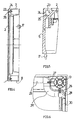
- the reference numeral 1 denotes in the figures a housing cover of a plastic housing (not otherwise shown), which comprises e.g. under plaster installable junction box for receiving connecting rails. Safety devices, etc. has.
- the housing cover 1 shown with a cutout at 50 has a front wall 2, are formed in the windows 3 and 4 for access to the arranged in the distribution box safety devices.
- a bolt guide is formed, of which in the Fig. 1 and 3 the guides 13 to 15 are visible.
- bolts for fixing the housing cover 1 to the distribution box can be inserted.
- the head of these bolts has a laterally projecting beard.
- tabs 16 and 17 are formed, of which the plug 16 in Fig. 3 and the plug 17 in Fig. 5 is visible.
- About the sockets 16 and 17 of the housing cover 1 in the above-mentioned distribution box can be latched.
- the housing integrated hollow sections are designated, which circulate like a frame at the edge of the front wall 2, wherein the frame formed by the hollow sections 18 and 19 at 20 and 21, that is in the region of Indentations 9 and 10, is interrupted.
- the hollow profile is formed in the bump corner region of each of the side walls 5 to 8 and the front wall 2 of the housing cover 1, wherein, as in particular from 4 and 5 shows a profile leg 23 through the front wall 2 of the housing cover 1 and a profile leg 24 through one of the side walls 5 to 8 of the housing cover 1 is formed.
- the hollow profile is 18 and 19 away from the side walls and guided around the respective bolt guide, wherein, as in particular from Fig. 6 and 7 can be seen, in this section of the hollow profile, a profile leg 23 'is formed by the graduated in this area front wall 2 of the housing cover 1.
- the profile leg 25 corresponds here a profile leg 25 ', and there is another, projecting into the housing interior profile leg 26 is provided.
- the led away from the side walls of the housing cover 1 sections of the hollow sections 18, 19 with the profile legs 23 ', 25' and 26 are stabilizing webs 27 and 28 with the housing interior projecting part of the respective bolt guide, in Fig. 6 the bolt guide 13, connected.
- the reference numerals 31 and 32 are used in the production of the housing cover by plastic injection openings used, which is subjected to the already solidified on the outer skin material of an internal pressure by a pressurized gas during the injection process, that the hollow sections 18, 19 form.
- a pressurized gas during the injection process, that the hollow sections 18, 19 form.
- GID method pressurization the compressed gas generates the cavity of the hollow profile, thereby ensuring a material expansion, wherein the plastic material under the action of the internal pressure in the forming the hollow profiles tool area against the inner wall of the injection mold.
- the hollow sections are arranged to save space in the corner region at the edge of the front wall, so that the installation space inside the housing is hardly reduced by this measure.
- the housing is sufficiently stiffened, so that there is no need to connect at this point the hollow sections 18 and 19 to a closed frame.
- Fig. 1 to 6 Similar hollow profile circumferentially along the bump corners between the cabinet rear wall and the side walls to be formed.
- the door 2a could include further deformations for stiffening including further, e.g. have the frame parts connecting hollow sections.
- FIG. 10 where a housing cover for a distributor housing is shown.
- hollow profiles are formed at opposite side edges of a front wall 2b, of which in the Fig. 10 the hollow profile 60 is visible.
- the hollow sections 18, 19 of the embodiment of Fig. 1 to 7 These hollow sections are formed only over part of their circumference through the front wall 2a and perpendicular side walls 60 and 61.
- At the sides perpendicular to the hollow profiles of the housing cover 1 is provided at 63 and 64 with stiffening ribs, which provide in conjunction with the hollow profiles for a large torsional rigidity of the housing cover.
- a housing cover 1c of a distributor housing is shown, in which on a housing front wall 2c, offset from the edge of the front wall, a front wall stiffening hollow profile 65 is formed in the form of a closed frame.
- the embodiment of Fig. 12 shows a distribution box lid 1 d, which is different from the housing cover 1 of the embodiment of Fig. 1 to 7 only differs in that is formed between the edge of the hollow profiles 18d and 19d extending transversely across the front wall 2d of the housing cover 1d further hollow section 40.
- the hollow profile 40 is formed integrally with the housing cover by the GID method.
Landscapes
- Engineering & Computer Science (AREA)
- Power Engineering (AREA)
- Casings For Electric Apparatus (AREA)
Description
- Die Erfindung betrifft ein Gehäuse für Elektroinstallationseinrichtungen, insbesondere für Verteiler, Zählerplätze und dergleichen, das ein mit dem Gehäuse verbundenes, das Gehäuse stabilisierendes Hohlprofil aufweist.
- Ein derartiges Gehäuse, das als Wandplatten flache Hohlprofilplatten aufweist, die durch Winkelstücke miteinander verbunden sind, geht aus der
CH-A-554629 - Die
EP-A-0008051 beschreibt eine Geräteabdeckung, die aus Profilteilen, die jeweils einen Rand der Abdeckung bilden, einsteckbaren Eckverbindern und einer Abdeckplatte zusammengesteckt ist. - Der vorliegenden Erfindung liegt die Aufgabe zugrunde, ein Gehäuse für Elektroinstallationseinrichtungen der eingangs erwähnten Art zu schaffen, das eine erhöhte Stabilität aufweist.
- Das diese Aufgabe lösende Gehäuse nach der Erfindung ist dadurch gekennzeichnet, dass das Hohlprofil mit seinen Profilwänden einstückig durchgehend um zumindest eine Ecke des Gehäuses herum verläuft.
- Die Hohlprofile lassen sich unter Anwendung des bekannten GID-Verfahrens erzeugen, bei dem das Werkstück in der Spritzgußform vor der vollständigen Erstarrung einer Gasinnendruckbeaufschlagung unterzogen wird.
- Ein solches, z.B. unter Integrationen in eine Gehäusewand einstückig mit dem Gehäuse ausgebildetes Hohlprofil kann dem Gehäuse auch bei geringer Wanddicke eine hohe Festigkeit verleihen. Vorteilhaft wird auch für das Hohlprofil selbst im Vergleich zu Versteifungen, die wie Versteifungsrippen durch bloße Verdickung der Gehäusewand gebildet sind, verhältnismäßig wenig Material benötigt. Insbesondere läßt sich durch ein Hohlprofil eine Materialanhäufung vermeiden, welche die Gefahr der Bildung von Einfallstellen an der Gehäuseoberfläche in sich birgt, die das Aussehen eines solchen Kunststoffgehäuses stark beeinträchtigen können.
- In einer bevorzugten Ausführungsform der Erfindung erstreckt sich das Hohlprofil wenigstens abschnittsweise entlang dem Rand einer Gehäusewand, wobei es insbesondere unmittelbar an dem Rand der Gehäusewand angrenzt und vorzugsweise rahmenartig um die Gehäusewand umläuft. Ein solches, z.B. an der Vorderwand eines Verteilergehäusedeckels oder der Rückwand eines Verteilergehäuses gebildetes Rahmenhohlprofil kann für eine hohe Verwindungssteifigkeit der Gehäuseteile sorgen und beeinträchtigt, selbst dann, wenn es sich im Querschnitt gesehen in den Gehäuseinnenraum hinein erstreckt, aufgrund seiner Anordnung am Gehäusewandrand kaum den zur Montage elektrischer Einrichtungen in dem Gehäuse nutzbaren Montageraum.
- Natürlich kann sich das Hohlprofil im Querschnitt gesehen auch vom Gehäuse nach außen erstrecken, so daß im Gehäuseinneren an keiner Stelle Montageraum verlorengeht.
- In der bevorzugten Ausführungsform der Erfindung ist das Hohlprofil derart in eine Gehäusewand integriert, daß es über einen Teil seines Umfangs durch die Gehäusewand selbst gebildet ist.
- Insbesondere kann das Hohlprofil im Eckenbereich winklig aneinandergrenzender Gehäusewände gebildet sein, z.B. im Eckenbereich zwischen einer Gehäuserückwand und den Gehäuseseitenwänden, wobei das Hohlprofil durch die winklig aneinanderstoßenden Gehäusewände und einen die Gehäusewände verbindenden Umfangsabschnitt gebildet ist.
- Ein solcher Umfangsabschnitt kann zur Bildung eines drei Ecken aufweisenden Hohlprofils gerade oder entsprechend einer Kreislinie gebogen sein. Ein solcher Umfangsabschnitt des Hohlprofils bildet dann im Gehäuseinneren eine Eckenabschrägung oder Eckenabrundung, durch welche die Größe des Gehäuseinnenvolumens nur geringfügig und insbesondere nur in einem für die Montage von Installationseinrichtungen kaum benötigten Raumbereich vermindert.
- In einer Ausführungsform der Erfindung kann sich das Hohlprofil auch im Abstand vom Rand einer Gehäusewand entlang der Wandfläche erstrecken.
- Die Erfindung soll nun anhand von Ausführungsbeispielen und der beiliegenden, sich auf diese Ausführungsbeispiele beziehenden Zeichnungen näher erläutert werden. Es zeigen:
- Fig. 1
- einen gemäß einem ersten Ausführungsbeispiel für die vorliegende Erfindung ausgebildeten Gehäusedeckel eines Verteilergehäuses in einer Vorderansicht,
- Fig. 2
- den Gehäusedeckel von
Fig. 1 in einer Schnittansicht gemäß Schnitt A2 - A2 vonFig. 1 , - Fig. 3
- den Gehäusedeckel von
Fig. 1 in einer Rückansicht, - Fig. 4
- den Gehäusedeckel von
Fig. 1 in einer Seitenansicht gemäß Schnitt D - D vonFig. 3 , - Fig. 5
- ein Detail des Gehäusedeckels von
Fig. 1 gemäß Schnitt G1 - G1 vonFig. 3 , - Fig. 6
- ein weiteres Detail des Gehäusedeckels von
Fig. 1 , - Fig. 7
- ein weiteres Detail des Gehäusedeckels von
Fig. 1 gemäß Schnitt K - K vonFig. 1 , - Fig. 8
- eine Teilansicht einer Verteilerschranktür gemäß einem zweiten Ausführungsbeispiel für die vorliegenden Erfindung,
- Fig. 9
- eine Teilschnittansicht der Tür von
Fig. 8 gemäß Schnitt C - C, - Fig. 10
- einen Gehäusedeckel für ein Verteilergehäuse gemäß einem dritten Ausführungsbeispiel für die vorliegende Erfindung,
- Fig. 11
- einen Gehäusedeckel für ein Verteilergehäuse gemäß einem vierten Ausführungsbeispiel für die vorliegende Erfindung, und
- Fig. 12
- ein Gehäusedeckel für ein Verteilergehäuse gemäß einem fünften Ausführungsbeispiel für die vorliegende Erfindung.
- Mit dem Bezugszeichen 1 ist in den Figuren ein Gehäusedeckel eines im übrigen nicht dargestellten Verteilergehäuses aus Kunststoff bezeichnet, welche einen z.B. unter Putz installierbaren Verteilerkastens für die Aufnahme von Anschlußschienen. Sicherungseinrichtungen usw. aufweist.
- Der mit einem Ausschnitt bei 50 dargestellte Gehäusedeckel 1 weist eine Vorderwand 2 auf, in der Fenster 3 und 4 für den Zugang zu dem in dem Verteilerkasten angeordneten Sicherungseinrichtungen gebildet sind.
- Zu der Vorderwand 2 des Gehäusedeckels 1 erstrecken sich senkrecht Längsseitenwände 5 und 6 sowie Schmalseitenwände 7 und 8.
- Neben den Fenstern 3 und 4 sind an der Vorderwand 2 am oberen und unteren Rand einander gegenüberliegend Einbuchtungen 9 und 10 gebildet, aus denen scheibenartige Griffteile 11 und 12 vorstehen.
- An den vier Ecken des Gehäusedeckels 1 ist jeweils eine Bolzenführung gebildet, von denen in den
Fig. 1 und3 die Führungen 13 bis 15 sichtbar sind. In die Bolzenführungen sind Bolzen zur Befestigung des Gehäusedeckels 1 an dem Verteilerkasten einsteckbar. Der Kopf dieser Bolzen weist einen seitlich vorstehenden Bart auf. - An den Längsseitenwänden 5 und 6 sind Stecknasen 16 und 17 gebildet, von denen die Stecknase 16 in
Fig. 3 und die Stecknase 17 inFig. 5 sichtbar ist. Über die Stecknasen 16 und 17 ist der Gehäusedeckel 1 in dem obengenannten Verteilerkasten einrastbar. - Mit dem Bezugszeichen 18 und 19 sind einstückig mit dem Gehäusedeckel 1 verbundene, in das Gehäuse integrierte Hohlprofile bezeichnet, die am Rand der Vorderwand 2 rahmenartig umlaufen, wobei der durch die Hohlprofile 18 und 19 gebildete Rahmen bei 20 und 21, das heißt im Bereich der Einbuchtungen 9 und 10, unterbrochen ist.
- Entlang der Randseiten ist das Hohlprofil im Stoßeckenbereich jeweils der Seitenwände 5 bis 8 und der Vorderwand 2 des Gehäusedeckels 1 gebildet, wobei, wie insbesondere aus
Fig. 4 und 5 hervorgeht, ein Profilschenkel 23 durch die Vorderwand 2 des Gehäusedeckels 1 und ein Profilschenkel 24 durch eine der Seitenwände 5 bis 8 des Gehäusedeckels 1 gebildet ist. Ein dritter, etwa kreisförmig gebogener Profilschenkel 25, der sich von der Vorderwand 2 zu einer der Seitenwände 5 bis 8 erstreckt, schließt den Hohlraum des Hohlprofils zum Gehäuseinnenraum hin ab. - In den Eckenbereichen ist das Hohlprofil 18 bzw. 19 von den Seitenwänden weg und um die jeweilige Bolzenführung herumgeführt, wobei, wie insbesondere aus
Fig. 6 und7 zu erkennen ist, in diesem Abschnitt des Hohlprofils ein Profilschenkel 23' durch die in diesem Bereich abgestufte Vorderwand 2 des Gehäusedeckels 1 gebildet ist. Dem Profilschenkel 25 entspricht hier ein Profilschenkel 25', und es ist ein weiterer, in den Gehäuseinnenraum vorstehender Profilschenkel 26 vorgesehen. Die von den Seitenwänden des Gehäusedeckels 1 weggeführten Abschnitte der Hohlprofile 18, 19 mit den Profilschenkeln 23', 25' und 26 sind über Stabilisierungsstege 27 und 28 mit dem in den Gehäuseinnenraum vorstehenden Teil der jeweiligen Bolzenführung, inFig. 6 der Bolzenführung 13, verbunden. - Mit den Bezugszeichen 29 und 30 sind von dem Profilschenkel 25 vorstehende Stege bezeichnet, die an den Enden abgewinkelt und mit den Seitenwänden 5 und 6 verbunden sind. Durch die Stege 29 und 30 ist an den Seitenwänden 5 und 6 auf der Gehäuseinnenseite jeweils eine Tasche gebildet.
- Mit dem Bezugszeichen 31 und 32 sind bei der Herstellung des Gehäusedeckels durch Kunststoffspritzen verwendete Öffnungen bezeichnet, über welche während des Spritzvorgangs das bereits an der Außenhaut erstarrte Material einer Innendruckbeaufschlagung durch ein Druckgas derart unterzogen wird, daß sich die Hohlprofile 18, 19 ausbilden. Bei dieser als GID-Verfahren bekannten Druckbeaufschlagung erzeugt das Druckgas den Hohlraum des Hohlprofils und sorgt dabei für eine Materialausdehnung, wobei sich das Kunststoffmaterial unter der Wirkung des Innendrucks in dem die Hohlprofile bildenden Werkzeugbereich gegen die Innenwand des Spritzwerkzeugs anlegt.
- Durch das rahmenartig umlaufende Hohlprofil wird eine außerordentliche Versteifung des Gehäusedeckels erreicht, die letztlich dazu führt, daß für den Gehäusedeckel (bei gleichbleibender Steifigkeit) eine deutlich geringere Materialmenge als ohne das Hohlprofil eingesetzt werden kann
- Die Hohlprofile sind platzsparend im Eckenbereich am Rand der Vorderwand angeordnet, so daß der Installationsraum im Gehäuseinneren durch diese Maßnahme kaum verkleinert ist.
- Im Bereich der Einbuchtungen ist das Gehäuse ausreichend versteift, so daß es keine Notwendigkeit besteht, an dieser Stelle die Hohlprofile 18 und 19 zu einem geschlossenen Rahmen zu verbinden.
- Es wird nun auf die
Fig. 8 und 9 bezug genommen, wo mit dem Bezugszeichen 2a eine ausschnittsweise in einem Eckenbereich dargestellte Tür 2a eines im übrigen nicht dargestellten Verteilerschranks bezeichnet ist. Geschlossen umlaufend ist am Türrand der Tür 2a ein Hohlprofil 34 mit einem Profilschenkel 23a und einem halbkreisförmigen Umfangsabschnitt 33 gebildet. - An der Schrankrückwand des Verteilerschrankes könnte ein dem Ausführungsbeispiel von
Fig. 1 bis 6 ähnliches Hohlprofil umlaufend entlang den Stoßecken zwischen der Schrankrückwand und den Seitenseitenwänden gebildet sein. - Über das gezeigte rahmenartige Hohlprofil hinaus könnte die Tür 2a weitere Verformungen zur Versteifung einschließlich weiterer, z.B. die Rahmenteile verbindender Hohlprofile aufweisen.
- Es wird nun auf
Fig. 10 bezug genommen, wo ein Gehäusedeckel für ein Verteilergehäuse dargestellt ist. Hier sind an gegenüberliegenden Seitenrändern einer Vorderwand 2b Hohlprofile gebildet, von denen in derFig. 10 das Hohlprofil 60 sichtbar ist. Wie die Hohlprofile 18, 19 des Ausführungsbeispiels vonFig. 1 bis 7 sind auch diese Hohlprofile nur über einen Teil Ihres Umfangs durch die Vorderwand 2a und dazu senkrechte Seitenwände 60 und 61 gebildet. An den zu den Hohlprofilen senkrechten Seiten ist der Gehäusedeckel 1 bei 63 und 64 mit Versteifungsrippen versehen, welche im Zusammenwirken mit den Hohlprofilen für eine große Verwindungssteifigkeit des Gehäusedeckels sorgen. - In
Fig. 11 ist ein Gehäusedeckel 1c eines Verteilergehäuses dargestellt, bei dem an einer Gehäusevorderwand 2c, abgesetzt vom Rand der Vorderwand ein die Vorderwand versteifendes Hohlprofil 65 in Form eines geschlossenen Rahmens gebildet ist. - In dem betreffenden Ausführungsbeispiel ist ähnlich wie bei dem Ausführungsbeispiel von
Fig. 8 und 9 ein Umfangsabschnitt des Hohlprofils 65 durch die Vorderwand 2b des Gehäuses und einen runden, von der Vorderwand 2b vorstehenden Umfangsabschnitt 33 gebildet. - Das Ausführungsbeispiel von
Fig. 12 zeigt einen Verteilerkastendeckel 1 d, welcher sich von dem Gehäusedeckel 1 des Ausführungsbeispiels vonFig. 1 bis 7 nur dadurch unterscheidet, daß sich zwischen den am Rand verlaufenden Hohlprofilen 18d und 19d ein sich quer über die Vorderwand 2d des Gehäusedeckels 1d erstreckendes weiteres Hohlprofil 40 gebildet ist. Wie die Hohlprofile 18d und 19d ist auch das Hohlprofil 40 einstückig mit dem Gehäusedeckel nach dem GID-Verfahren ausgebildet.
Claims (12)
- Gehäuse für Elektroinstallationseinrichtungen, insbesondere für Verteiler, Zählerplätze und dergleichen, das ein mit dem Gehäuse (2;2a;2b;2c) verbundenes, das Gehäuse (2;2a;2b;2c) stabilisierendes Hohlprofil (18,19;34;60;65) aufweist,
dadurch gekennzeichnet,
daß das Hohlprofil (18,19;34;60;65) mit seinen Profilwänden einstückig durchgehend um zumindest eine Ecke des Gehäuses (2;2a;2b;2c) herum verläuft. - Gehäuse nach Anspruch 1,
dadurch gekennzeichnet,
daß sich das Hohlprofil (18, 19; 34; 60; 65) wenigstens abschnittsweise entlang dem Rand einer Gehäusewand (2; 2a; 2b; 2c) erstreckt. - Gehäuse nach Anspruch 1 oder 2,
dadurch gekennzeichnet,
daß das Hohlprofil (18, 19; 34; 60; 65) wenigstens abschnittsweise am Rand einer Gehäusewand (2; 2a; 2b) verläuft. - Gehäuse nach einem der Ansprüche 1 bis 3,
dadurch gekennzeichnet,
daß das Hohlprofil (18, 19; 34; 65) an einer Gehäusewand (2; 2a; 2c) rahmenartig umlaufend ausgebildet ist. - Gehäuse nach Anspruch 4,
dadurch gekennzeichnet,
daß das rahmenartig umlaufende Hohlprofil (18, 19) unterbrochen ist. - Gehäuse nach einem der Ansprüche 1 bis 5,
dadurch gekennzeichnet,
daß das Hohlprofil (18, 19; 34; 60; 65) einstückig mit dem Gehäuse (2; 2a) ausgebildet ist. - Gehäuse nach einem der Ansprüche 1 bis 6,
dadurch gekennzeichnet,
daß sich im Querschnitt gesehen das Hohlprofil (18, 19; 34; 60; 65) von dem Gehäuse (2; 2a) nach außen oder/und in den Gehäuseinnenraum hinein erstreckt. - Gehäuse nach einem der Ansprüche 1 bis 7,
dadurch gekennzeichnet,
daß das Hohlprofil (18, 19; 34; 60; 65) über einen Teil seines Umfangs durch eine Gehäusewand (2;2a; 2b; 2c) gebildet ist. - Gehäuse nach Anspruch 8,
dadurch gekennzeichnet,
daß das Hohlprofil (18,19) im Eckenbereich winklig aneinandergrenzender Gehäusewände (2, 5 bis 8) durch die Gehäusewände (2, 5 bis 8) und einen die Gehäusewände verbindenden Umfangsabschnitt (25) gebildet ist. - Gehäuse nach Anspruch 9,
dadurch gekennzeichnet,
daß der Umfangsabschnitt (25) unter Bildung eines dreieckigen Hohlprofils gerade oder entsprechend einer Kreislinie gebogen ist. - Gehäuse nach einem der Ansprüche 1 bis 10,
dadurch gekennzeichnet,
daß das Hohlprofil (18, 19; 34;60; 65) durch Beaufschlagung des Werkstücks in einer Spritzgußform mit Gasinnendruck gebildet ist. - Gehäuse nach einem der Ansprüche 1 bis 11,
dadurch gekennzeichnet,
daß sich das Hohlprofil (40) im Abstand vom Rand einer Gehäusewand (2d) entlang der Wandfläche erstreckt.
Applications Claiming Priority (2)
| Application Number | Priority Date | Filing Date | Title |
|---|---|---|---|
| DE20014371U DE20014371U1 (de) | 2000-08-11 | 2000-08-11 | Gehäuse für Elektroinstallationseinrichtungen |
| DE20014371U | 2000-08-11 |
Publications (2)
| Publication Number | Publication Date |
|---|---|
| EP1180837A1 EP1180837A1 (de) | 2002-02-20 |
| EP1180837B1 true EP1180837B1 (de) | 2008-10-01 |
Family
ID=7945403
Family Applications (1)
| Application Number | Title | Priority Date | Filing Date |
|---|---|---|---|
| EP01118078A Expired - Lifetime EP1180837B1 (de) | 2000-08-11 | 2001-07-26 | Gehäuse für Elektroinstallationseinrichtungen |
Country Status (2)
| Country | Link |
|---|---|
| EP (1) | EP1180837B1 (de) |
| DE (2) | DE20014371U1 (de) |
Family Cites Families (3)
| Publication number | Priority date | Publication date | Assignee | Title |
|---|---|---|---|---|
| DE7224800U (de) * | 1972-07-03 | 1972-12-07 | Siemens Ag | Gerateschrank zur Aufnahme elektrischer Gerate, insbesondere elektrischer Installationsgerät« |
| DE2833950C2 (de) * | 1978-08-03 | 1982-10-21 | Brown, Boveri & Cie Ag, 6800 Mannheim | Geräteabdeckung für schutzisolierte Verteilungseinsätze |
| FR2436516A1 (fr) * | 1978-09-18 | 1980-04-11 | Hager Electro | Perfectionnements aux supports pour tableaux d'abonne a l'electricite |
-
2000
- 2000-08-11 DE DE20014371U patent/DE20014371U1/de not_active Expired - Lifetime
-
2001
- 2001-07-26 EP EP01118078A patent/EP1180837B1/de not_active Expired - Lifetime
- 2001-07-26 DE DE50114358T patent/DE50114358D1/de not_active Expired - Lifetime
Also Published As
| Publication number | Publication date |
|---|---|
| EP1180837A1 (de) | 2002-02-20 |
| DE50114358D1 (de) | 2008-11-13 |
| DE20014371U1 (de) | 2001-12-20 |
Similar Documents
| Publication | Publication Date | Title |
|---|---|---|
| DE69104687T2 (de) | Metallrahmen für einen schrank. | |
| DE19647814C2 (de) | Schaltschrank | |
| EP0939980B1 (de) | Rahmengestell mit einem boden- und einem deckrahmen aus einem profilstrang | |
| DE3020906C2 (de) | Formvorrichtung zum Umspritzen oder Umgießen des Randes eines flächigen Bauteiles | |
| DE102015112563A1 (de) | Verbindungsanordnung zum Verbinden eines Pfostens an einem Rahmenprofil eines Fensters oder einer Türe aus Kunststoff | |
| DE2427427B2 (de) | Elektrische maschine mit einer mehrteiligen, koerperschallisolierten haube | |
| DE2615891C2 (de) | ||
| DE69300349T2 (de) | Schalldämpfende Lüftungsvorrichtung mit einem länglichen blockförmigen Gehäuse und einem spaltförmigen Lüftungskanal. | |
| DE10026706B4 (de) | Klemmenleiste für Einspritzvorrichtungen | |
| DE29822718U1 (de) | Befestigungssystem für Gehäusedeckel an Gehäusen von Kraftmaschinen | |
| EP3036806B1 (de) | Kabelkanal sowie verfahren zum herstellen eines dreidimensional verlaufenden kabelkanals | |
| DE2243329A1 (de) | Geraeuschdaemmendes, wandbildendes bauelement | |
| DE29924372U1 (de) | Einführungsplatte für Rohrsysteme | |
| EP0867641B1 (de) | Mehrteiliges Getriebegehäuse | |
| DE20014371U1 (de) | Gehäuse für Elektroinstallationseinrichtungen | |
| DE19620082C2 (de) | Kabelverzweigerschrank | |
| EP1336468A2 (de) | Zahnriemen aus Kunststoff und Verfahren und Vorrichtung zum Herstellen eines Zahnriemens | |
| DE2810764A1 (de) | Chassis zur befestigung von elektromechanischen oder pneumatischen geraeten | |
| DE3012817A1 (de) | Form zum herstellen von formkoerpern aus beton | |
| DE69607307T2 (de) | Abstandshaltermodul, insbesondere für modulare elektrische Geräte | |
| DE29713879U1 (de) | Abstandhalter | |
| DE102007046725B4 (de) | Verfahren zum Bereitstellen eines Spritzgussbauteils und Spritzgussbauteil | |
| DE9414692U1 (de) | Fahrgestell für ein medizinisches Gerät | |
| DE69805558T2 (de) | Befestigungsgestell insbesondere für elektrische Geräte, Pfosten und Riegel dafür | |
| DE69004000T2 (de) | Vorrichtung aus formgeschäumtem Polystyrol für den Schutz von Objekten gegen Stösse. |
Legal Events
| Date | Code | Title | Description |
|---|---|---|---|
| PUAI | Public reference made under article 153(3) epc to a published international application that has entered the european phase |
Free format text: ORIGINAL CODE: 0009012 |
|
| AK | Designated contracting states |
Kind code of ref document: A1 Designated state(s): AT BE CH CY DE DK ES FI FR GB GR IE IT LI LU MC NL PT SE TR |
|
| AX | Request for extension of the european patent |
Free format text: AL;LT;LV;MK;RO;SI |
|
| 17P | Request for examination filed |
Effective date: 20020622 |
|
| AKX | Designation fees paid |
Free format text: DE FR GB IT |
|
| 17Q | First examination report despatched |
Effective date: 20070627 |
|
| GRAP | Despatch of communication of intention to grant a patent |
Free format text: ORIGINAL CODE: EPIDOSNIGR1 |
|
| RAP1 | Party data changed (applicant data changed or rights of an application transferred) |
Owner name: HAGER ELECTRO GMBH & CO. KG |
|
| GRAS | Grant fee paid |
Free format text: ORIGINAL CODE: EPIDOSNIGR3 |
|
| GRAA | (expected) grant |
Free format text: ORIGINAL CODE: 0009210 |
|
| AK | Designated contracting states |
Kind code of ref document: B1 Designated state(s): DE FR GB IT |
|
| REG | Reference to a national code |
Ref country code: GB Ref legal event code: FG4D Free format text: NOT ENGLISH |
|
| REF | Corresponds to: |
Ref document number: 50114358 Country of ref document: DE Date of ref document: 20081113 Kind code of ref document: P |
|
| PLBE | No opposition filed within time limit |
Free format text: ORIGINAL CODE: 0009261 |
|
| STAA | Information on the status of an ep patent application or granted ep patent |
Free format text: STATUS: NO OPPOSITION FILED WITHIN TIME LIMIT |
|
| 26N | No opposition filed |
Effective date: 20090702 |
|
| GBPC | Gb: european patent ceased through non-payment of renewal fee |
Effective date: 20090726 |
|
| PG25 | Lapsed in a contracting state [announced via postgrant information from national office to epo] |
Ref country code: GB Free format text: LAPSE BECAUSE OF NON-PAYMENT OF DUE FEES Effective date: 20090726 |
|
| PGFP | Annual fee paid to national office [announced via postgrant information from national office to epo] |
Ref country code: IT Payment date: 20120724 Year of fee payment: 12 |
|
| REG | Reference to a national code |
Ref country code: DE Ref legal event code: R082 Ref document number: 50114358 Country of ref document: DE Representative=s name: PATENTANWAELTE BERNHARDT/WOLFF PARTNERSCHAFT, DE Ref country code: DE Ref legal event code: R082 Ref document number: 50114358 Country of ref document: DE Representative=s name: CABINET NUSS, FR |
|
| PG25 | Lapsed in a contracting state [announced via postgrant information from national office to epo] |
Ref country code: IT Free format text: LAPSE BECAUSE OF NON-PAYMENT OF DUE FEES Effective date: 20130726 |
|
| REG | Reference to a national code |
Ref country code: DE Ref legal event code: R082 Ref document number: 50114358 Country of ref document: DE Representative=s name: CABINET NUSS, FR |
|
| REG | Reference to a national code |
Ref country code: FR Ref legal event code: PLFP Year of fee payment: 16 |
|
| REG | Reference to a national code |
Ref country code: FR Ref legal event code: PLFP Year of fee payment: 17 |
|
| REG | Reference to a national code |
Ref country code: FR Ref legal event code: PLFP Year of fee payment: 18 |
|
| PGFP | Annual fee paid to national office [announced via postgrant information from national office to epo] |
Ref country code: DE Payment date: 20180727 Year of fee payment: 18 Ref country code: FR Payment date: 20180726 Year of fee payment: 18 |
|
| REG | Reference to a national code |
Ref country code: DE Ref legal event code: R119 Ref document number: 50114358 Country of ref document: DE |
|
| PG25 | Lapsed in a contracting state [announced via postgrant information from national office to epo] |
Ref country code: DE Free format text: LAPSE BECAUSE OF NON-PAYMENT OF DUE FEES Effective date: 20200201 |
|
| PG25 | Lapsed in a contracting state [announced via postgrant information from national office to epo] |
Ref country code: FR Free format text: LAPSE BECAUSE OF NON-PAYMENT OF DUE FEES Effective date: 20190731 |