EP1179408A1 - Antriebsvorrichtung für die bewegliche Formaufspannplatte einer Spritzgiessmaschine - Google Patents
Antriebsvorrichtung für die bewegliche Formaufspannplatte einer Spritzgiessmaschine Download PDFInfo
- Publication number
- EP1179408A1 EP1179408A1 EP01110533A EP01110533A EP1179408A1 EP 1179408 A1 EP1179408 A1 EP 1179408A1 EP 01110533 A EP01110533 A EP 01110533A EP 01110533 A EP01110533 A EP 01110533A EP 1179408 A1 EP1179408 A1 EP 1179408A1
- Authority
- EP
- European Patent Office
- Prior art keywords
- lever
- drive device
- axis
- electric motor
- platen
- Prior art date
- Legal status (The legal status is an assumption and is not a legal conclusion. Google has not performed a legal analysis and makes no representation as to the accuracy of the status listed.)
- Granted
Links
- 238000001746 injection moulding Methods 0.000 title claims description 25
- 230000033001 locomotion Effects 0.000 claims abstract description 48
- 239000012530 fluid Substances 0.000 claims description 10
- 238000002347 injection Methods 0.000 claims description 7
- 239000007924 injection Substances 0.000 claims description 7
- 230000008878 coupling Effects 0.000 claims description 4
- 238000010168 coupling process Methods 0.000 claims description 4
- 238000005859 coupling reaction Methods 0.000 claims description 4
- 210000001520 comb Anatomy 0.000 claims description 3
- 230000007935 neutral effect Effects 0.000 claims description 3
- 230000000903 blocking effect Effects 0.000 claims 9
- 230000005540 biological transmission Effects 0.000 description 14
- 210000002414 leg Anatomy 0.000 description 7
- 239000004033 plastic Substances 0.000 description 7
- 229920003023 plastic Polymers 0.000 description 7
- 230000000694 effects Effects 0.000 description 3
- 210000003127 knee Anatomy 0.000 description 3
- 230000001154 acute effect Effects 0.000 description 2
- 238000013459 approach Methods 0.000 description 2
- 238000011156 evaluation Methods 0.000 description 2
- 238000009434 installation Methods 0.000 description 2
- 238000004519 manufacturing process Methods 0.000 description 2
- 238000006243 chemical reaction Methods 0.000 description 1
- 239000002131 composite material Substances 0.000 description 1
- 238000006073 displacement reaction Methods 0.000 description 1
- 239000013013 elastic material Substances 0.000 description 1
- 229920001971 elastomer Polymers 0.000 description 1
- 230000002349 favourable effect Effects 0.000 description 1
- 239000000463 material Substances 0.000 description 1
- 239000002184 metal Substances 0.000 description 1
- 238000000034 method Methods 0.000 description 1
- 229920002635 polyurethane Polymers 0.000 description 1
- 239000004814 polyurethane Substances 0.000 description 1
- 230000001105 regulatory effect Effects 0.000 description 1
- 239000007921 spray Substances 0.000 description 1
Images




Classifications
-
- B—PERFORMING OPERATIONS; TRANSPORTING
- B29—WORKING OF PLASTICS; WORKING OF SUBSTANCES IN A PLASTIC STATE IN GENERAL
- B29C—SHAPING OR JOINING OF PLASTICS; SHAPING OF MATERIAL IN A PLASTIC STATE, NOT OTHERWISE PROVIDED FOR; AFTER-TREATMENT OF THE SHAPED PRODUCTS, e.g. REPAIRING
- B29C45/00—Injection moulding, i.e. forcing the required volume of moulding material through a nozzle into a closed mould; Apparatus therefor
- B29C45/17—Component parts, details or accessories; Auxiliary operations
- B29C45/64—Mould opening, closing or clamping devices
- B29C45/66—Mould opening, closing or clamping devices mechanical
Definitions
- the invention relates to a drive device, in particular for the method the movable platen of an injection molding machine is used and having the features from the preamble of claim 1.
- Such a drive device has two important different requirements to fulfill. On the one hand, it should be the platen to close and Open the mold as quickly as possible so that the cycle time for the production of a fitting can be kept small. Secondly, it should Mold platen and thus the whole mold against the high spray pressure can hold great strength. On the one hand, there are high movements Running speed, on the other hand, are high without substantial movement To exercise powers. Such requirements may apply to the Closing unit also for the ejectors or the injection unit of a plastic injection molding machine put. For example, when injecting plastic into the mold towards the plasticizing screw at a relatively high speed towards the mold until the mold is completely filled with plastic. Will in Connection to the so-called plastic melt in the mold Exposed pressure, the drive must have a high force without essential Apply the movement of the plasticizing screw.
- Injection molding machines with purely hydraulic drive devices are known.
- a correspondingly large effective area on a hydraulic piston very large locking forces are generated.
- then during the closing movement requires a lot of hydraulic fluid to the large Hydraulic piston adjacent and increasing during the closing movement
- one can also for the closing movement, for which no excessive force is required Use separate, smaller hydraulic cylinders, such as one injection molding machine known from US-A 4 030 299 is shown.
- the large hydraulic piston is taken along, whereby the volume of the large pressure chamber increases and pressure medium out a container flows into the pressure chamber via a suction valve. If the movable platen has reached its front end position, that closes Cavitation valve.
- the large pressure chamber is powered by a second hydraulic pump Via a directional valve further pressure medium is supplied, whereby the pressure in the Pressure chamber rises.
- the directional control valve switched and a high pressure built up in the large pressure chamber, for what only a little pressure fluid is required.
- electromechanical drive devices can be because Electric motors can run at high speed in a relatively simple way high speed for the positioning movement of a mold platen or one reach other movable members of an injection molding machine. Weakness An electromechanical drive device involves the generation of a high one Force.
- the invention has for its object a drive device having the features from the preamble of claim 1, to develop further, that with little effort and without taking up a lot of space On the one hand, a quick positioning movement is possible in the axis of the injection molding machine is and on the other hand, a large force effect can be achieved.
- the drive device according to the invention has the features from the characterizing part of claim 1.
- at least the short one extends Lever arm of the two-armed lever, which acts as a force translator between the straight lines movable output element of the electromotive drive unit and serves the movable platen, substantially perpendicular to the direction of movement the platen. Installation space behind the platen is not needed. Due to a high speed of the electric motor during the Adjustment movement can be a high speed despite the lever ratio Platen can be reached.
- the two-armed Lever an elongated lever and therefore, for example, from a metal strand particularly easy to manufacture.
- the lever can according to claim 3 also be an angle lever, with the long lever arm lying in one area that is not for other functions, for example for removal and removal the fittings, is needed.
- the lever can be easily located outside of the range be when he has a handlebar according to claim 6, which has a Swivel joint is articulated on the short lever arm, with the movable platen is coupled.
- the lever can according to claim 8 without have a lever axle fixed to the frame.
- the electric motor is one pivot axis parallel to the lever axis and fixed to the frame.
- the electric motor drive does not apply directly on the two-armed lever. Rather is between the output element and the two-armed lever inserted a knee lever assembly. This means one more Force transmission stage in the lever gear between the electromotive Drive and the platen.
- the toggle lever arrangement is also advantageously below the stationary one Mold platen of the injection molding machine housed. With the toggle lever arrangement one gets one during the closing movement of the platen changing power transmission. The power transmission should be special be large when the mold is closed and the high locking force is applied shall be. Accordingly, the toggle assembly during the Closing movement of the movable platen more stretched.
- the power transmission can also be used to generate the high locking force be increased that according to claim 15, the length at least a lever arm of the lever is changed. It is particularly advantageous here according to claim 16, the length of both lever arms by a shift to change the lever axis. This is preferred by the in the claims 17 to 27 contained structural configurations achieved, with one Training according to claim 23, only an electric motor is required.
- a high locking force in which not only the ratio of the length of the both arms of the two-armed lever given power transmission, but one stronger power transmission is also obtained by training according to Claim 28.
- the handlebar on which the two-armed lever between his two arms is mounted an element of a toggle lever arrangement, those for the generation of a locking force in the direction of a neutral position, including a fully extended or fully flexed position of the toggle assembly is understood, adjustable. Doing so keeps the shape closed the handlebar and the swivel between it and the two-armed lever as well the two-armed lever initiated the force for the platen.
- the toggle arrangement of which the handlebar is an element in front of the movable platen in the area the stationary platen and the injection unit.
- Further advantageous embodiments of a drive device according to claim 28 can be found in claims 30 to 34.
- the measures according to Claims 28 to 34 are also in a drive device according to the invention advantageous in the embodiment according to claim 6.
- an injection molding machine e.g. a plastic injection molding machine
- a frame 10 with several legs 11 and with cross members 12, which is attached to the legs 11 at a distance from a foundation are.
- the crossbeams carry a mounting plate 13 which is fixed to the frame and which an injection channel 14 is provided to 15 plastic material from a plasticizing into one consisting of two mold halves 16 and 17, one of which frame-fixed platen 13 is worn, composite shape to be able to inject.
- On the crossbars 12 is a movable platen 18, which carries the other mold half, guided in a straight line. This Mold platen is in one of the mold platen fixed to the frame 13 distant end position when the mold for removing a fitting is open.
- the platen is removed this end position in a quick adjustment movement to the fixed platen moved up. It is essentially only to accelerate the Platen 18 a of course the size of the machine and thus the Mass of the platen and half of the mold requires greater force. After the mold has been closed, the movable platen 18 are held on the platen 13 with a large locking force, so that the mold halves are not expanded by the injection pressure and are inaccurate Fittings are created.
- the platen 18 is moved and locked by a drive device, which has an electric motor drive 25 and a lever gear 26.
- the electric motor drive 25 includes an electric motor 27 with a rotating output shaft not shown.
- the electric motor is located just above the foundation and approximately vertically below the frame Mold mounting plate 13. With its housing, it is around a horizontal axis 28 pivotable in a direction perpendicular to the direction of movement of the platen 18 extending plane and that except in the fourth embodiment 5 is fixed to the frame. Except in the fourth embodiment the electric motor 27 on two opposite legs 11 in the middle hung between them.
- the motor shaft is secured against twisting attached threaded spindle 29 extended by a bore of a physical Bearing axis 30 passes and in the bore in an internal thread Bearing axis engages.
- the geometric axis 31 of the bearing axis 30 runs parallel to the pivot axis 28 of the electric motor 27.
- the lever gear 26 has two parallel and Identical lever arrangements on both sides of the platen 18 on.
- Each lever arrangement has a two-armed lever 32, which one end via a swivel 33 with a to the platen 18th stationary and parallel to the axes 28 and 31 axis of rotation 34 the platen 18 is connected.
- a bearing pin engages at the other end the bearing axis 30 in a bore of a lever 32. So every lever is 32 via a rotary joint 35, the axis of which is the axis 31, with the bearing axis 30 coupled. This is the straight line in the direction of the axis of the electric motor 27 Movable output element of the electric motor drive 25.
- each lever 32 is connected via a further swivel joint 36 coupled to a handlebar 37 which is associated with the open shape End position of the platen 18, which is shown in Figure 1, approximately horizontally away from the vertically extending lever 32 in the direction of the fixed one Platen 13 to and in the operating state shown in Figure 1 in Direction of the resultant force of the two at the ends of the lever arms 39 and 40 of the lever 32 engaging forces and spaced from the axis of rotation 38 of the swivel joint 36 via a further swivel joint 39 with an axis of rotation 41 the frame 10 of the machine is coupled.
- the handlebar 37 is in the area the crossbar 12.
- the distance of the axis of rotation representing the lever axis 38 of the axis of rotation 31 of the swivel at the output element of the electromotive Drive unit 25 is about three times the distance of the Axis of rotation 38 from the axis of rotation 34 of the swivel between the lever 32 and the platen 18.
- Each lever 32 thus has a long lever arm 39 between the two axes 38 and 31 and a short lever arm 40 between the two axes 38 and 34.
- the electric motor 27 is controlled such that the threaded spindle 29 rotates in such a direction that the bearing axis 30th migrates away from the housing of the electric motor 27.
- the levers 32 viewed according to Figure 1, pivoted clockwise about the axis of rotation 38.
- the free end of the short lever arm 40 moves onto the mold-mounting platen 13 and takes the movable platen 18 with it. Since the Position of the axis of rotation 34 with respect to the platen 18 is fixed during the movement of the platen 18 of the handlebar 37 about the axis of rotation 41 and the electric motor drive 25 pivoted slightly about the axis of rotation 28.
- the bearing axis 30 and the lever 32 also rotate against each other. If the mold is closed, the electric motor drive 25 a locking force can be generated by the ratio of long lever arm too short lever arm is greater than the force with which the electric motor 27 the threaded spindle 29 can act, or the force with which the screw drive 29, 30 wants to strain.
- the electric motor 27 is an electric motor which can be regulated in terms of its speed, with which move the platen 18 according to a desired speed profile can be.
- the plastic injection molding machine of which parts shown in Figures 1 and 2 is a so-called two-platen injection molding machine.
- Such injection molding machines are characterized by a short overall length in the direction of movement of the movable Platen 18 from. It can be seen in particular from FIG. 1 that that by the drive device for the movable platen 18 the Overall length is not increased. The same applies to all versions shown.
- the frame 10 of the machine is identical to that of the embodiment of Figures 1 and 2.
- the shown Parts of the frame are therefore provided with the same reference numbers. Identity also exists with regard to the lever 32 and the handlebar 37.
- the various Sections, swivel joints and axes of rotation of these parts are therefore provided with the same reference numbers as in Figures 1 and 2.
- Differently to the embodiment of Figures 1 and 2 is the arrangement of the electric motor drive 25 and the type of motion transmission from its output element 30 to the long lever arm 39.
- the electromotive Drive 25 is now at a greater distance from the foundation suspended about an axis 28 between two legs 11. However, its longitudinal axis now runs in the end position of the platen 18 not horizontally, but vertically.
- the threaded spindle 29 does not extend that Motor shaft shown in more detail in the direction of the foundation and engages in Thread of a bearing axis 30, but now not two levers 32, but the ends of two links 45 and 46 of a toggle lever arrangement on each side outsourced.
- the other end of a link 45 is connected via a pivot 35 to one Lever 32 coupled while the other end of a handlebar 46 via a fixed frame Swivel joint 47 is connected to the frame 10.
- the lever 32 In the end position of the platen 18 shown, the lever 32 extends again vertically and the handlebar 37 horizontally.
- the two handlebars 45 and 46 of the Toggle lever arrangement form an obtuse angle with each other.
- To close the shape of the threaded spindle 29 is rotated so that the bearing axis 30 in Moves down towards the foundation. This will make the swivel 35 pushed away from the swivel joint 47 and the lever 32, viewed in accordance with FIG. 3, pivoted clockwise about the axis of rotation 38.
- the toggle lever arrangement 45, 46 When the form closed is, the toggle lever arrangement 45, 46 is almost stretched, so that the electromotive Drive 25 can generate a large locking force.
- the electric motor drive 25 has been pivoted slightly, since the bearing axis 30 is in a circle around the axis of the swivel joint 47 must move.
- the embodiment of Figure 4 corresponds in terms of arrangement the two-armed lever 32 and the electromotive drive 25 the first Embodiment.
- the function of the electric motor drive 25 when locking the shape somewhat differently than in the embodiment according to FIG. 1 must then namely over the self-locking thread of the spindle 29 and the bearing axis 30 are only supported by a force, but cannot be built up.
- a toggle lever arrangement is used to build up the locking force the handlebar 37 modified from the first two embodiments Handlebar 52 and a toothed segment 53 belong.
- At one end is the handlebar 52 just like the handlebar 37 of the first two exemplary embodiments Swivel joint 36 coupled to the axis of rotation 38 with the lever 32.
- the tooth segment 53 has an axis of rotation 41, the position of which is equal to the axis of rotation 41 from FIGS Figures 1 to 3 is rotatably mounted on the frame 10.
- the handlebar 52 extends beyond the axis of rotation 41 and is via a pivot joint 54 with an axis of rotation 55 coupled to the toothed segment 53.
- the tooth segment meshes with its teeth 56 with a pinion 57, which is on the shaft of another electric motor 58 sits, whose axis of rotation runs parallel to the axes of rotation 38, 55 and 41.
- the connecting lines between the axes of rotation 38 and 55 and between the Rotation axes 41 and 55 in the plane of the drawing close to one another at an acute angle on. If tooth segment 53 is now considered, as shown in FIG rotated clockwise, the knee lever 52, 53 is further bent, whereby the axis of rotation 38 must move closer to the axis of rotation 41.
- the mold is closed first Electric motor 27 operated.
- the toggle assembly 52 and 53 remains essentially in the position shown. It only changes the location of the Handlebar 52 because the axis of the lever 32 because of the fixed position of the axis of rotation 34 must move slightly upwards to the platen 18. Is the shape closed, the electric motor 27 is stopped and the electric motor 58 is controlled. This rotates the toothed segment 53 counterclockwise, so that the handlebar 52 pulls the lever 32 closer to the axis of rotation 41 and a high one Locking force is generated.
- the embodiment of Figure 5 has like the embodiment of FIG Figure 4 shows a handlebar 52, which is part of a toggle lever arrangement, the structure serves the locking force.
- the electric motor 27 is now not only used for pivoting of the lever 32, that is, for closing the mold, but also for adjustment the toggle lever assembly used.
- the toothed segment 53 is second link of the toggle lever arrangement according to Figure 4 by a two-armed Lever 86 replaced, which about the same axis of rotation 41 as the toothed segment 53 Figure 4 is rotatably hinged to the frame 10 and its two arms pointed Include angles with each other.
- a first arm 87 of the lever 86 extends from the axis of rotation 41 to an axis of rotation 55 of a swivel joint 54 that the handlebar 52 is rotatably connected to the lever 86.
- the arm 87 and the Handlebars 52 form an acute angle with each other.
- the swivel and the axis of rotation between the link 52 and the arm 87 are given the same reference numbers provided like the swivel and the axis of rotation between the handlebars 52 and the toothed segment 53 from FIG.
- a second arm 88 of the lever 86 is substantially longer than the arm 87 and extends with the mold 16, 17 open from the axis of rotation 41 vertically downward up to the electric motor 27. This is now not pivotable about the axis 28 Frame 10, but mounted on the long arm 88 of the lever 86. Between this arm 88 and the frame 10, a spring 89 is clamped, the lever 86 clockwise and up to a certain limit force on one stop 85 fixed to the frame.
- This stop can be made from an elastic Material, for example rubber or polyurethane.
- the shape is closed to close Electric motor 27 operated in such a direction of rotation that the lever 32, after 5 viewed, pivoted counterclockwise about the axis of rotation 38 and the mold clamping plate 18 moved up to the mold clamping plate 13 becomes.
- Electric motor 27 operated in such a direction of rotation that the lever 32, after 5 viewed, pivoted counterclockwise about the axis of rotation 38 and the mold clamping plate 18 moved up to the mold clamping plate 13 becomes.
- the electric motor 27 is only light pivoted about the axis of the joint 28.
- the toggle lever arrangement 52, 86 remains essentially in the position shown. It just changes something Location of the handlebar 52 because the axis of the lever 32 because of the fixed position of the The axis of rotation 34 must move slightly upward to the platen 18.
- the electric motor 27 continues to operate even after the mold has been closed. There however, if the lever 32 can no longer be pivoted, that of the electric motor increases 27 exerted strong. The spring 89 can no longer handle the lever 86 to hold at stop 85. Rather, the lever 86 is opposed by the electric motor pivoted clockwise and thereby the toggle lever arrangement 52, 86 brought close to the inverse stretch, in which the angle between the connecting lines between the axes of rotation 38, 41 and 55 is zero. It will be high Locking force exerted on the platen 18 and 13.
- the electric motor 27 is turned in the opposite direction operated, the lever 86 first returning to the stop 85 and then the lever 32 is pivoted.
- lever 32 available, the one via a pivot 35 with the output element electromotive drive 25 bearing axis 30 and via a rotary joint 33 with an axis of rotation 34 with the movable platen 18 is coupled.
- the lever 32 is now not directly via a swivel joint 36 with an axis of rotation 38 connected to a link 37 which is pivotable about the axis of rotation 41 is mounted on the frame 10 of the injection molding machine. Rather, between that Lever 32 and the handlebar 37 inserted another lever 60, the handlebar 37 is connected via the swivel joint 36.
- the lever 60 is still over Swivel joint 61 with an axis of rotation 62 which is between the two axes of rotation 34 and 38 runs parallel to these, coupled to the lever 32.
- the lever 60 is with respect to the axis of rotation 38 a two-armed lever, which is close to the Axis of rotation 31 extends between the lever 32 and the bearing axis 30.
- the two electric motors 27 and 66 are speed-controlled and are via one electrical control unit 68 and amplifier stages 69 and 70 controlled.
- the electric motor 27 rotates in such a direction that the end of the lever 32 away from the electric motor 27.
- the one on the moving Platen 18 to be exerted via the swivel joint 33 is so low that the spring 65 can hold the two levers 32 and 60 in contact with one another and these two levers rotate together about the axis of rotation 38.
- the spindle 67 is moved by the electric motor 66 to the lever 60 without closing it touch so that it can be turned easily.
- the electric motor 66 is switched off.
- the electric motor 27 which is still energized force exerted on the lever 32 rises sharply.
- the spring 65 can change the position of the axis of rotation 34 of the swivel joint 33 relative to the axis of rotation 62 of the hinge 61 no longer prevent, so that with a further pivoting of the lever 32, the axis of rotation 62 becomes the lever axis. This is the relationship between the long lever arm 39 and the short lever arm 40 of the lever 32 have become even larger, so that from the electric motor drive 25 the lever 32 acting force is translated to a high degree.
- the lever 60 by the Spindle 67 supported.
- the electric motor 66 is controlled so that the spindle 67 the lever 32 and 60 now pivots counterclockwise.
- the electric motor 27 also has the side opposite the threaded spindle 29 has an output via which Via a slip clutch 101, a pinion 102 arranged in the motor axis is rotatable. From this is a gear via a small intermediate gear 103 104 drivable, which is arranged in the direction of its axis and via a Push joint non-rotatably with a splined section 105 of a second Threaded spindle 106 is coupled. This runs parallel to the motor axis and Axis of the threaded spindle 29 and passes through a spindle nut 107, which is fixed on the electric motor 27.
- the slip clutch, the Gears 102, 103 and 104, the threaded spindle 106 and the spindle nut 107 thus make the pivoting movements of the electric motor 27 about the axis of rotation 28 with.
- the threaded spindle 106 protrudes from the spindle nut 107 in the direction the lever 60 out and has a small distance from this according to FIG.
- the interlocking threads of threaded spindle 106 and spindle nut 107 are designed so that the engagement is self-locking, that is, that the threaded spindle is not under only by an axial force exerted on it Rotation can be moved axially.
- the threaded spindle can As additional security against such an undesired axial movement the threaded spindle can, as shown in FIG. 7, provide a brake 108 be operated to prevent rotation of the threaded spindle can.
- the brake 108 can be anywhere between the secondary side the slip clutch and the threaded spindle arranged inclusive his. In the present case, it acts on the secondary disk 109 Slip clutch.
- the electric motor 27 rotates as in the exemplary embodiment 6 in such a direction that the end of the lever 32 from Electric motor 27 is removed and the platen 18 of the platen 13 approaches.
- the electric motor 27 drives via the slip clutch 101 the threaded spindle 106 so that it the lever 60 with a small distance follows.
- the electric motor that continues to receive current increases 27 strongly exerted on the lever 32.
- the lever now pivots 32 about the axis of rotation 62.
- the lever 60 pivots counterclockwise about the axis of rotation 38 and lies against the self-locking threaded spindle 106 on.
- the Electric motor 27 continues to rotate and now moves the lever 32 about the axis of rotation 62.
- gear 102 is seated directly a stub of the shaft of the electric motor 27. It drives over the idler gear 103 on the gear 104, which is arranged coaxially with the threaded spindle 106 is. There is a clutch between the gear 104 and the threaded spindle 106 110 inserted. Gear 104, clutch 110 and threaded spindle 106 cannot be moved in the axial direction.
- the threaded spindle is self-locking into a spindle nut 107, which is guided axially against rotation, that is, itself axially moved when turning the threaded spindle 106, and according to FIG. 8 a small one Distance from the lever 60.
- the axis of the threaded spindle 106th components 104, clutch 110 and spindle nut 107 together with the threaded spindle 106 make the swiveling movements of the Electric motor 27 about the axis of rotation 28 with.
- the electric motor 27 rotates as in the exemplary embodiment 6 or 7 in such a direction that the end of the lever 32nd removed from the electric motor 27 and the platen 18 of the platen 13 approaches.
- the electric motor 27 drives over the closed one Clutch 110 on the threaded spindle 106 so that the spindle nut 107th follows lever 60 a short distance apart.
- the clutch 110 is opened.
- the electric motor 27 which is still energized force exerted on the lever 32 rises sharply.
- the lever 32 now pivots about the axis of rotation 62.
- the lever 60 pivots counterclockwise the axis of rotation 38 and lies against the self-locking spindle nut 107.
- the electric motor 27 continues to rotate and now only moves the lever 32 around the Axis of rotation 62.
- the electric motor 66 is with a spindle 67 from Figure 6 replaced by a single-acting hydraulic cylinder 90, the piston 91 via a piston rod 92 at a large distance from the axis of rotation 38 is articulated on the lever 60.
- the slight change in the vertical position of the articulation point during a pivoting of the levers 32, 60 can by pivoting of the piston 91 or by pivoting the entire Hydraulic cylinders 90 are balanced.
- the piston 91 delimits a pressure space 93, the hydraulic fluid via a check valve 94 opening towards it can flow from a hydraulic fluid reservoir 96 which is on a higher Level than the hydraulic cylinder 90 is arranged.
- a 2/2-way seat valve 95 which is operated by an electromagnet from a rest position in which there is a connection from the pressure chamber 93 to the Container 96 sealed leakage-free, be switched to a through position can.
- a pressure transducer 97 is connected to the pressure chamber 93 electrical signal corresponding to the pressure prevailing in the pressure chamber an evaluation electronics not shown there.
- the piston is in the form of closing 91 pulled by the lever 60, the pressure chamber 93 increasing and hydraulic fluid from the reservoir 96 flows through the check valve 94.
- the valve 95 is in its rest position, so it blocks. If the form is closed, the force of the spring 65 is no longer sufficient to pivot the lever 60 to prevent relative to the lever 32.
- the lever 60 therefore exercises on the Piston 91 exerts a force that leads to a corresponding pressure build-up in the pressure chamber 93 and leads to hydraulic support of the lever 60.
- the height the pressure in the pressure chamber 93 is a measure of the closing force applied.
- valve 95 is opened so that hydraulic fluid is out the pressure chamber 93 can be displaced into the container 96.
- 10 and 11 is the electromotive drive 25 with its output element 30 via a rotary joint 35 with an axis of rotation 31 coupled with a two-armed lever 72, which is shown in FIG End position of the platen 18 as the lever 32 of the above Embodiments extends vertically.
- the lever 72 is also via a swivel joint 36 coupled to an axis of rotation 38 with a link 73, which via a Swivel joint with an axis of rotation 41 pivotally mounted on the frame 10 of the machine is.
- the axis of rotation 38 lies below one through the axis of rotation 41 horizontal lines.
- the lever 72 has one from the axis of rotation 38 Long axis of rotation 31 reaching long lever arm 74 and a ring gear 75, the centric to the axis of rotation 38 and its distance from the axis of rotation 38 is essential is smaller than the length of the lever arm 74.
- the radius of the ring gear 75 can be viewed as the length of a short lever arm 76, the angular position thereof to the other lever arm, however, when the lever is pivoted 72 changes.
- the lever 72 is symmetrical with respect to formed and arranged a central plane of the machine.
- a handlebar 73 is present on each side of the Mold mounting plates.
- Via swivel joints 33 with one Common axis of rotation 34 is on the movable platen 18 this encircling U-shaped further two-armed lever 80 articulated.
- the short Lever arm of this lever 80 is formed by a ring gear 81 which with the ring gear 75 of the lever 72 combs.
- the lever 80 is smaller than overall lever 72 has both a shorter long arm and a shorter short one Arm as the lever 72. It is connected to the handlebar 73 via a swivel joint 82, its axis of rotation 83 from the axis of rotation 38 between the lever 72 and the handlebar 73 is spaced such that the two ring gears 75th and 81 are held in engagement with each other.
- Figures 10 and 11 are the platen 18, the electromotive Drive unit 25 and the lever gear 26 shown in positions in which the Mold halves 16 and 17 far apart, so the shape is open.
- the Axes of rotation 34, 83, 38 and 31 lie vertically one above the other.
- the electric motor 27 is now driven to rotate in such a direction, that the bearing axis 30 moves closer to him.
- the lever 72 is thus pivoted about the axis of rotation 38, viewed in FIG. 6, counterclockwise. Because of the coupling via the sprockets 75 and 81, the second Lever 80 pivoted about the axis of rotation 83 clockwise.
- the embodiment of Figure 12 has like the first embodiment both sides of the platen 13 and 18, a lever gear 26 with a two-armed lever 32, which is identical to the first embodiment via a located at the end of its long lever arm 39 bearing axis 30 and one Threaded spindle 29 can be pivoted by an electric motor 27.
- the Electric motor 27 can be pivoted about an axis of rotation 28 fixed to the frame. He is now unlike the first embodiment, not below the fixed platen 13, but shifted in the direction of the injection unit.
- the lever 32 which runs essentially vertically, is opposite the first one Embodiment migrated towards the fixed platen 13 and is located in the direction of displacement of the movable platen 18 viewed at the level of the fixed platen 13. Via a swivel 36 with a lever axis 38 now fixed to the frame.
- the lever 32 is on a crossbar 12 rotatably mounted.
- the lever 32 is via a swivel joint 115 with an axis of rotation 116 connected to a handlebar 117 which is movable Platen 18 extends out and over the pivot 33 with the Axis of rotation 34 is coupled to the platen 18.
- a swivel joint 115 with an axis of rotation 116 connected to a handlebar 117 which is movable Platen 18 extends out and over the pivot 33 with the Axis of rotation 34 is coupled to the platen 18.
- the axis of rotation 34 in addition to the axis of rotation 34 also intersects the Axis of rotation 116 the axis of the plasticizing cylinder 15 and thus the axis of the Machine.
- the handlebar 117 is made by the two axes of rotation 34 and 116 spanned plane, in the state according to Figure 12 with that through the axis of rotation 34 and the machine axis spanned plane coincides, down bent out so that, seen from the side, the two halves of the tool 16 and 17 are only slightly covered and are still easily accessible.
- the exemplary embodiment according to FIG. 13 is largely identical to the exemplary embodiment 1 and 2 and in turn has a lever gear 26 with two lever arrangements acting in parallel and identically constructed on both Sides of the platen 18.
- the electric motor 27 is different than in the embodiment of Figure 12 again on the legs 11 around the Axle 28 is pivotally mounted, but is arranged so that the threaded spindle 29 points obliquely upwards in the direction of the plasticizing cylinder 15.
- Any lever arrangement has a two-armed lever 32, which is designed as an angle lever and at the end of its short lever arm 40 with a swivel 33 one fixed to the platen 18 and parallel to the axis 28 Axis of rotation 34 is connected to the platen 18.
- the lever arm 40 extends substantially perpendicular to the direction of movement of the movable Mold platen 18. In Figure 13, he just takes the vertical one Position on.
- the long lever arm 39 closes with the short lever arm 40 an angle of approximately 120 degrees and extends from the lever axis 38 from obliquely down over the legs 11. Intervenes at its end Journal of the bearing axis 30 in a hole.
- Each lever is thus 32nd via a rotary joint 35, the axis of which is the axis 31, with the bearing axis 30 and thus pivotable by the electric motor 27.
- each lever 32 is coupled to a link 37 via the pivot joint 36 having the axis of rotation 38. which extends from the axis of rotation 38 in the direction of the fixed platen 13 and the legs 11 and is pivotally mounted on the frame 10 via the swivel joint 39 with the axis of rotation 41 fixed to the frame.
- a connecting line lying in the plane of the drawing runs between the two axes of rotation 38 and 41 in the direction of the force results F res of the two forces F 1 and F 2 acting on the lever arms 39 and 40 of the lever 32.
- the positions of lever 32 and handlebar 37 shown in FIG. 13 are only assumed when the mold is closed when the high locking force is necessary.
- the electric motor 27 is controlled such that the threaded spindle 29 rotates in such a direction that the bearing axis 30 on the Housing of the electric motor 27 migrates.
- the lever 32 after 13 viewed, pivoted clockwise about the axis of rotation 38. Furthermore is also the further movement as in the embodiment of FIG Figures 1 and 2, so that a detailed description does not appear necessary.
Landscapes
- Engineering & Computer Science (AREA)
- Manufacturing & Machinery (AREA)
- Mechanical Engineering (AREA)
- Moulds For Moulding Plastics Or The Like (AREA)
Abstract
Description
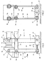
- Figur 1
- in einer Ansicht in Richtung der Drehachsen das erste Ausführungsbeispiel, bei dem ein zweiarmiger Hebel an der beweglichen Formaufspannplatte einer Spritzgießmaschine und am Ausgangselement eines elektromotorischen Antriebs angelenkt ist und der Hebel sowohl bei der Stellbewegung der beweglichen Formaufspannplatte als auch bei der Zuhaltung der Form bei gleich bleibenden Hebelarmlängen verschwenkt wird,
- Figur 2
- eine Ansicht des ersten Ausführungsbeispiels senkrecht zu den Drehachsen in Richtung des Pfeiles A aus Figur 1,
- Figur 3
- eine Ansicht in Richtung der Drehachsen auf das zweite Ausführungsbeispiel, bei dem zwischen dem Ausgangselement des elektromotorischen Antriebs und dem langen Hebelarm des zweiarmigen Hebels eine Kniehebelanordnung eingefügt ist und dadurch zum Zuhalten der Form eine höhere Kraftübersetzung des Hebelgetriebes erhalten wird als zu Beginn der Schließbewegung der beweglichen Formaufspannplatte,
- Figur 4
- wiederum in Ansicht in Richtung der Drehachsen des Hebelgetriebes das dritte Ausführungsbeispiel, bei dem ein mit dem zweiarmigen Hebel über ein Drehgelenk gekoppelter Lenker Teil einer Kniehebelanordnung ist und diese Kniehebelanordnung über ein Zahnradgetriebe von einem zweiten Elektromotor verstellt wird, um die hohe Zuhaltekraft zu erzeugen,
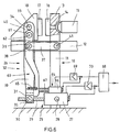
- Figur 5
- in Ansicht in Richtung der Drehachsen des Hebelgetriebes das vierte Ausführungsbeispiel, bei dem wie bei dem dritten Ausführungsbeispiel ein mit dem zweiarmigen Hebel über ein Drehgelenk gekoppelter Lenker Teil einer Kniehebelanordnung ist und diese Kniehebelanordnung über den auch den zweiarmigen Hebel verschwenkenden Elektromotor verstellt wird, um die hohe Zuhaltekraft zu erzeugen,
- Figur 6
- in Ansicht in Richtung der Drehachsen des Hebelgetriebes das fünfte Ausführungsbeispiel, bei dem zum Zuhalten der Form eine erhöhte Kraftübersetzung dadurch erhalten wird, daß die Länge der Hebelarme verändert wird, wobei dazu ein zweiter Elektromotor verwendet wird,
- Figur 7
- als sechstes Ausführungsbeispiel eine Variante des fünften Ausführungsbeispiels mit nur einem Elektromotor mit zwei Abtrieben und einer dem einen Antrieb nachgeordneten Rutschkupplung,
- Figur 8
- als siebtes Ausführungsbeispiel eine weitere Variante des fünften Ausführungsbeispiels wiederum mit nur einem Elektromotor mit zwei Abtrieben und einer dem einen Antrieb nachgeordneten Schaltkupplung,
- Figur 9
- als achtes Ausführungsbeispiel eine weitere Variante des fünften Ausführungsbeispiels bei dem zur Veränderung der Hebellänge ein Hydrozylinder vorhanden ist,
- Figur 10
- in Ansicht in Richtung der Drehachsen das neunte Ausführungsbeispiel, bei dem mit dem mit dem Ausgangselement des elektromotorischen Antriebs unmittelbar verbundene zweiarmiger Hebel und der Formaufspannplatte ein weiterer zweiarmiger Hebel eingefügt ist, der mit dem ersten Hebel über eine Verzahnung gekoppelt ist,
- Figur 11
- eine Ansicht des neunten Ausführungsbeispiels in Richtung des Pfeiles B aus Figur 10,
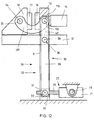
- Figur 12
- in einer Ansicht in Richtung der Drehachsen ein zehntes Ausführungsbeispiel, das ähnlich einfach wie das erste Ausführungsbeispiel aufgebaut ist, bei dem jedoch der zweiarmige Hebel über einen Lenker mit der beweglichen Formaufspannplatte gekoppelt ist und eine gestellfeste Drehachse besitzt, und
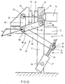
- Figur 13
- in einer Ansicht in Richtung der Drehachsen ein elftes Ausführungsbeispiel, das prinzipiell wie das erste Ausführungsbeispiel aufgebaut ist, bei dem jedoch der zweiarmige Hebel ein Winkelhebel ist.
Claims (36)
- Antriebsvorrichtung für eine Spritzgießmaschine, insbesondere für die in einer Stellbewegung geradlinig zu bewegende und mit hoher Schließkraft zu zu haltende Formaufspannplatte (18) einer Spritzgießmaschine mit einem Maschinengestell (10),dadurch gekennzeichnet,mit einer elektromotorischen Antriebseinheit (25), die einen Elektromotor (27) und ein in Richtung der Achse des Elektromotors (27) geradlinig bewegbares Ausgangselement (30) aufweist,und mit einem Hebelgetriebe (26), das in der Kraftkette zwischen dem Ausgangselement (30) der elektromotorischen Antriebseinheit (25) und der Formaufspannplatte (18) angeordnet,daß das Hebelgetriebe (26) einen zweiarmigen Hebel (32, 72) mit einem kurzen Hebelarm (40,76) und mit einem langen Hebelarm (39,74) umfaßt,daß sich der lange Hebelarm (39,74) in der Kraftkette näher als der kurze Hebelarm (40, 76) am Ausgangselement (30) des elektromotorischen Antriebs (25) befindet, unddaß zumindest der kurze Hebelarm (40; 76) des Hebels (32, 72) im wesentlichen senkrecht zur Bewegungsrichtung der Formaufspannplatte (18) verläuft.
- Antriebsvorrichtung nach Anspruch 1, dadurch gekennzeichnet, daß der Hebel (32, 72) ein gestreckter Hebel ist und dementsprechend auch der lange Hebelarm (39, 74) im wesentlichen senkrecht zur Bewegungsrichtung der Formaufspannplatte (18) verläuft.
- Antriebsvorrichtung nach Anspruch 1, dadurch gekennzeichnet, daß der Hebel (32) ein Winkelhebel ist und der lange Hebelarm (39) insbesondere mit der Richtung der Bewegung der Formaufspannplatte (18) beim Schließen der Form einen Winkel kleiner als 90 Grad einschließt.
- Antriebsvorrichtung nach einem vorhergehenden Anspruch, dadurch gekennzeichnet, daß der Elektromotor (27) unterhalb einer festen Formaufspannplatte (18) oder der Einspritzeinheit (15) der Spritzgießmaschine angeordnet ist.
- Antriebsvorrichtung nach einem vorhergehenden Anspruch, dadurch gekennzeichnet, daß das Hebelgetriebe (26) über ein Drehgelenk (33) mit einer bezüglich der beweglichen Formaufspannplatte (18) ortsfesten Drehachse (34) mit dieser Formaufspannplatte (18) gekoppelt ist.
- Antriebsvorrichtung nach einem vorhergehenden Ansprüche, dadurch gekennzeichnet, daß der Hebel (32) über einen Lenker (117), der über ein Drehgelenk (115) am kurzen Hebelarm (40) angelenkt ist, mit der beweglichen Formaufspannplatte (18) gekoppelt ist.
- Antriebsvorrichtung nach einem der Ansprüche 1 bis 5, dadurch gekennzeichnet, daß der Hebel (32) über ein Drehgelenk (33) mit der beweglichen Formaufspannplatte (18) gekoppelt ist und eine Hebelachse (38) besitzt, die während der Stellbewegung der Formaufspannplatte (18) verlagerbar ist.
- Antriebsvorrichtung nach einem der Ansprüche 1 bis 6, dadurch gekennzeichnet, daß der Hebel (32) eine gestellfeste Hebelachse (38) besitzt.
- Antriebsvorrichtung nach einem der Ansprüche 1 bis 7, dadurch gekennzeichnet, daß der Hebel (32, 72) über ein Drehgelenk (36), dessen Drehachse (38) die Hebelachse ist, mit einem verschwenkbaren Lenker (37, 52, 73) gekoppelt ist.
- Antriebsvorrichtung nach Anspruch 9, dadurch gekennzeichnet, daß der Lenker (37, 52, 73) im wesentlichen in Richtung der Resultierenden der an den beiden Hebelarmen (39, 40) angreifenden Kräfte ausgerichtet ist.
- Antriebsvorrichtung nach Anspruch 9 oder 10, dadurch gekennzeichnet, daß sich der Lenker (37, 52, 73) auf derselben Seite des Hebels (32, 72) wie eine feste Formaufspannpiatte (13) befindet.
- Antriebsvorrichtung nach einem der Ansprüche 9 bis 11, dadurch gekennzeichnet, daß der Lenker (37, 73) im Abstand zu dem Drehgelenk (36) zwischen ihm und dem Hebel (37, 73) um eine gestellfeste Drehachse (41) verschwenkbar ist.
- Antriebsvorrichtung nach einem vorhergehenden Anspruch, dadurch gekennzeichnet, daß das Ausgangselement (30) der elektromotorischen Antriebseinheit (25) über ein Drehgelenk (35), dessen Drehachse (31) parallel zu der Hebelachse (38) verläuft, unmittelbar mit dem Hebel (32, 72) gekoppelt ist und daß der Elektromotor (27) um eine zur Hebelachse (38) parallele und gestellfeste Drehachse (28) verschwenkbar ist.
- Antriebsvorrichtung nach einem der Ansprüche 1 bis 13, dadurch gekennzeichnet, daß eine Kniehebelanordnung (45, 46) mit einem ersten Glied (45) und mit einem mit diesem über ein erstes Drehgelenk (44) verbundenen zweiten Glied (46) vorhanden ist, daß das erste Glied (45) über ein vom ersten Drehgelenk (44) beabstandeten zweiten Drehgelenk (35) mit dem Hebel (32) und das zweite Glied (46) mit einem vom ersten Drehgelenk (44) beabstandeten dritten Drehgelenk (47) mit dem Maschinengestell (10) verbunden ist und daß die Kniehebelanordnung (45, 46) vom Ausgangselement (30) der elektromotorischen Antriebseinheit (25) streck- und beugbar ist.
- Antriebsvorrichtung nach einem vorhergehenden Anspruch, dadurch gekennzeichnet, daß die Länge wenigstens eines Hebelarms (39, 40) des Hebels (32) veränderbar ist.
- Antriebsvorrichtung nach Anspruch 15, dadurch gekennzeichnet, daß die Länge der Hebelarme (39, 40) durch eine Verlagerung der Hebelachse (38) veränderbar ist.
- Antriebsvorrichtung nach Anspruch 16, dadurch gekennzeichnet, daß ein zweiter Hebel (60) vorhanden ist, der um eine Hebelachse (38) verschwenkbar und mit dem ersten Hebel (32) über ein Drehgelenk (61) gekoppelt ist, daß der Abstand dieses Drehgelenks (61) vom Ende des kurzen Hebelarms (40) des ersten Hebels (32) kleiner als der Abstand der Hebelachse (38) des zweiten Hebels (60) vom Ende des kurzen Hebelarms (40) des ersten Hebels (32) ist, daß der zweite Hebel (60) und der erste Hebel (32) gemeinsam um die Hebelachse (38) des zweiten Hebels (60) verschwenkbar sind und daß bei Abstützung des zweiten Hebels (60) gegen ein Zurückschwenken durch eine Blockiereinrichtung (64) der erste Hebel (32) allein um die Achse (62) des Drehgelenks (61) zwischen ihm und dem zweiten Hebel (60) verschwenkbar ist.
- Antriebsvorrichtung nach Anspruch 17, dadurch gekennzeichnet, daß der erste Hebel (32) und der zweite Hebel (60) durch eine lösbare Kupplung (65) zu einer festen Einheit verbindbar und als solche von der unter Umgehung des zweiten Hebels (60) am ersten Hebel (32) angreifenden elektromotorischen Antriebseinheit (25) verschwenkbar sind.
- Antriebsvorrichtung nach Anspruch 18, dadurch gekennzeichnet, daß die lösbare Kupplung eine vorgespannte Feder (65) umfaßt, die bis zu einer Grenzkraft den zweiten Hebel (60) an einem Anschlag des ersten Hebels (32) hält.
- Antriebsvorrichtung nach Anspruch 18 oder 19, dadurch gekennzeichnet, daß die beiden Hebel (32, 60) durch die lösbare Kupplung (65) nahe am Ende des langen Hebelarms (39) des ersten Hebels (32) miteinander koppelbar sind.
- Antriebsvorrichtung nach einem der Ansprüche 17 bis 20, dadurch gekennzeichnet, daß die Blockiereinrichtung (64) für den zweiten Hebel (60) einen Anschlag (67, 106, 107) besitzt, der dem zweiten Hebel (60) nach- und vorwegführbar ist.
- Antriebsvorrichtung nach einem der Ansprüche 17 bis 21, dadurch gekennzeichnet, daß die Blockiereinrichtung (64) für den zweiten Hebel (60) mit dem Elektromotor (27) die gleichen Schwenkbewegungen ausführt
- Antriebsvorrichtung nach einem der Ansprüche 17 bis 22, dadurch gekennzeichnet, daß der Anschlag (106, 107) der Blockiereinrichtung (64) für den zweiten Hebel (60) durch den Elektromotor (27) nach- und vorwegführbar ist, wobei zwischen einem entsprechenden Abtrieb des Elektromotors (27) und dem Anschlag (106, 107) eine Schaltkupplung (110) oder eine Rutschkupplung 101) eingefügt ist.
- Antriebsvorrichtung nach Anspruch 21 oder 22, dadurch gekennzeichnet, daß der Anschlag (67) der Blockiereinrichtung (64) dem zweiten Hebel (60) durch einen zweiten Elektromotor (66) nach- und vorwegführbar ist.
- Antriebsvorrichtung nach einem der Ansprüche 17 bis 24, dadurch gekennzeichnet, daß die Blockiereinrichtung (64) einen selbsthemmenden Gewindetrieb mit einer Gewindespindel (67, 106) und einer Spindelmutter (107) umfaßt.
- Antriebsvorrichtung nach einem der Ansprüche 17 bis 22, dadurch gekennzeichnet, daß die Blockiereinrichtung (64) für den zweiten Hebel (60) einen Hydrozylinder (90) mit einem an den zweiten Hebel (60) angelenkten und einen Druckraum (93) begrenzenden Kolben (91), einen Druckflüssigkeitsvorratsbehälter und Ventilmittel (94, 95) aufweist, mit denen der Druckflüssigkeitsaustausch zwischen dem Druckraum (93) und dem Druckflüssigkeitsvorratsbehälter steuerbar ist.
- Antriebsvorrichtung nach Anspruch 26, dadurch gekennzeichnet, daß der in dem Druckraum (93) anstehende Druck durch einen Druckaufnehmer (97) erfaßbar ist.
- Antriebsvorrichtung nach einem der Ansprüche 1 bis 14, dadurch gekennzeichnet, daß der Lenker (52) ein Element einer Kniehebelanordnung (52, 53, 52, 86) ist, die für die Erzeugung einer Zuhaltekraft in Richtung einer Neutrallage verstellbar ist.
- Antriebsvorrichtung nach Anspruch 28, dadurch gekennzeichnet, daß sich der Lenker (52) vom Hebel (32) aus mit geringer Abweichung in Richtung der Bewegung der Formaufspannplatte (18) beim Schließen der Form erstreckt und mit dem zweiten Kniehebelelement (53, 86) einen Winkel kleiner 90 Grad einschließt und daß die Kniehebelanordnung (52, 53; 52, 86) in Richtung einer Neutrallage verstellbar ist, in der der Lenker (52) und das zweite Kniehebelelement (53, 86) maximal gebeugt sind.
- Antriebsvorrichtung nach Anspruch 29, dadurch gekennzeichnet, daß die Kniehebelanordnung (52, 86) durch den Elektromotor (27) verstellbar ist.
- Antriebsvorrichtung nach Anspruch 30, dadurch gekennzeichnet, daß der Elektromotor (27) am zweiten Kniehebelelement (86) schwenkbar gelagert ist und daß das zweite Kniehebelelement (86) während der Stellbewegung der beweglichen Formaufspannplatte (18) durch eine lösbare Blockiervorrichtung (89) gegen eine Verschwenkung blockierbar ist.
- Antriebsvorrichtung nach Anspruch 31, dadurch gekennzeichnet, daß die lösbare Blockiervorrichtung eine vorgespannte Feder (89) und einen Anschlag (85) umfaßt, an den das zweite Kniehebelelement (86) von der Feder (89) andrückbar ist.
- Antriebsvorrichtung nach Anspruch 29, dadurch gekennzeichnet, daß die Kniehebelanordnung (52, 53) durch einen zweiten Elektromotor (58) verstellbar ist.
- Antriebsvorrichtung nach Anspruch 33, dadurch gekennzeichnet, daß das zweite Kniehebelelement (53) mit einer Verzahnung (56) versehen ist und von dem zweiten Elektromotor (58) ein Zahnrad (57) antreibbar ist, das mit der Verzahnung (56) des zweiten Kniehebelelements (53) kämmt.
- Antriebsvorrichtung nach einem vorhergehenden Anspruch, dadurch gekennzeichnet, daß der zweiarmige Hebel (72) an seinem kurzen Hebelarm (76) ein Zahnsegment (75) aufweist, daß an der beweglichen Formaufspannplatte (18) ein Hebelarm eines zweiten zweiarmigen Hebels (80) drehbar gelagert ist, der an seinem anderen Hebelarm ein Zahnsegment (81) aufweist, das mit dem Zahnsegment ((75) am ersten zweiarmigen Hebel (72) in Eingriff ist.
- Antriebsvorrichtung nach Anspruch 35, dadurch gekennzeichnet, daß außer dem ersten Hebel (72) auch der zweite Hebel (80) über ein Drehgelenk (82), dessen Drehachse (83) die Hebelachse des zweiten Hebels (80) ist, mit dem verschwenkbaren Lenker (73) gekoppelt ist, wobei der Abstand der Drehachsen (38, 83) der beiden Drehgelenke (36, 82) voneinander gleich der Summe der Radien der beiden Zahnsegmente (75, 81) ist.
Applications Claiming Priority (6)
| Application Number | Priority Date | Filing Date | Title |
|---|---|---|---|
| DE10039514 | 2000-08-08 | ||
| DE10039514 | 2000-08-08 | ||
| DE10040312 | 2000-08-17 | ||
| DE10040312 | 2000-08-17 | ||
| DE10041668 | 2000-08-24 | ||
| DE10041668 | 2000-08-24 |
Publications (2)
| Publication Number | Publication Date |
|---|---|
| EP1179408A1 true EP1179408A1 (de) | 2002-02-13 |
| EP1179408B1 EP1179408B1 (de) | 2007-07-04 |
Family
ID=27214003
Family Applications (1)
| Application Number | Title | Priority Date | Filing Date |
|---|---|---|---|
| EP01110533A Expired - Lifetime EP1179408B1 (de) | 2000-08-08 | 2001-04-28 | Antriebsvorrichtung für die bewegliche Formaufspannplatte einer Spritzgiessmaschine |
Country Status (3)
| Country | Link |
|---|---|
| EP (1) | EP1179408B1 (de) |
| AT (1) | ATE366173T1 (de) |
| DE (2) | DE50112679D1 (de) |
Cited By (3)
| Publication number | Priority date | Publication date | Assignee | Title |
|---|---|---|---|---|
| CN112721268A (zh) * | 2020-12-29 | 2021-04-30 | 深圳昶晖科技有限公司 | 一种压力机 |
| CN116833491A (zh) * | 2023-08-21 | 2023-10-03 | 上海新建重型机械有限公司 | 一种具有定位效果的球磨机底板加工用攻丝装置 |
| CN118683688A (zh) * | 2024-07-30 | 2024-09-24 | 江苏省无锡交通高等职业技术学校 | 一种船舶破冰组件及其使用方法 |
Families Citing this family (2)
| Publication number | Priority date | Publication date | Assignee | Title |
|---|---|---|---|---|
| DE102006042697B4 (de) * | 2006-09-12 | 2009-11-12 | Magna Powertrain Ag & Co Kg | Spannvorrichtung mit Taumelbolzen |
| DE102008023648A1 (de) * | 2008-05-15 | 2009-11-19 | Wittmann Battenfeld Gmbh | Spritzgießmaschine |
Citations (6)
| Publication number | Priority date | Publication date | Assignee | Title |
|---|---|---|---|---|
| US3830614A (en) * | 1972-12-01 | 1974-08-20 | A Kurtz | Injection molding machine |
| FR2239329A1 (en) * | 1973-08-02 | 1975-02-28 | Serta | Tool support claws for extrusion/blow moulding machine - to allow horizontal transfer of the moulding to subsequent operations |
| US5362222A (en) * | 1993-08-31 | 1994-11-08 | Cincinnati Milacron Inc. | Injection molding machine having a vector controlled AC drive system |
| DE4411649A1 (de) * | 1993-09-30 | 1995-04-06 | Karl Hehl | Spritzgießmaschine zur Verarbeitung plastifizierbarer Massen |
| EP0768165A2 (de) * | 1995-09-27 | 1997-04-16 | SIPA S.p.A. | Verbesserte Vorrichtung zum Herstellen von Behältern aus Kunststoff |
| DE19916399A1 (de) * | 1999-04-06 | 2000-10-19 | B & W Kunststoffmaschb & Hande | Antriebsvorrichtung für das Schließen und Öffnen einer zweiteiligen Form |
-
2001
- 2001-04-28 EP EP01110533A patent/EP1179408B1/de not_active Expired - Lifetime
- 2001-04-28 DE DE50112679T patent/DE50112679D1/de not_active Expired - Lifetime
- 2001-04-28 DE DE10120999A patent/DE10120999A1/de not_active Withdrawn
- 2001-04-28 AT AT01110533T patent/ATE366173T1/de not_active IP Right Cessation
Patent Citations (6)
| Publication number | Priority date | Publication date | Assignee | Title |
|---|---|---|---|---|
| US3830614A (en) * | 1972-12-01 | 1974-08-20 | A Kurtz | Injection molding machine |
| FR2239329A1 (en) * | 1973-08-02 | 1975-02-28 | Serta | Tool support claws for extrusion/blow moulding machine - to allow horizontal transfer of the moulding to subsequent operations |
| US5362222A (en) * | 1993-08-31 | 1994-11-08 | Cincinnati Milacron Inc. | Injection molding machine having a vector controlled AC drive system |
| DE4411649A1 (de) * | 1993-09-30 | 1995-04-06 | Karl Hehl | Spritzgießmaschine zur Verarbeitung plastifizierbarer Massen |
| EP0768165A2 (de) * | 1995-09-27 | 1997-04-16 | SIPA S.p.A. | Verbesserte Vorrichtung zum Herstellen von Behältern aus Kunststoff |
| DE19916399A1 (de) * | 1999-04-06 | 2000-10-19 | B & W Kunststoffmaschb & Hande | Antriebsvorrichtung für das Schließen und Öffnen einer zweiteiligen Form |
Cited By (4)
| Publication number | Priority date | Publication date | Assignee | Title |
|---|---|---|---|---|
| CN112721268A (zh) * | 2020-12-29 | 2021-04-30 | 深圳昶晖科技有限公司 | 一种压力机 |
| CN116833491A (zh) * | 2023-08-21 | 2023-10-03 | 上海新建重型机械有限公司 | 一种具有定位效果的球磨机底板加工用攻丝装置 |
| CN116833491B (zh) * | 2023-08-21 | 2023-12-26 | 上海新建重型机械有限公司 | 一种具有定位效果的球磨机底板加工用攻丝装置 |
| CN118683688A (zh) * | 2024-07-30 | 2024-09-24 | 江苏省无锡交通高等职业技术学校 | 一种船舶破冰组件及其使用方法 |
Also Published As
| Publication number | Publication date |
|---|---|
| DE10120999A1 (de) | 2002-02-21 |
| ATE366173T1 (de) | 2007-07-15 |
| DE50112679D1 (de) | 2007-08-16 |
| EP1179408B1 (de) | 2007-07-04 |
Similar Documents
| Publication | Publication Date | Title |
|---|---|---|
| DE4329072C2 (de) | Durch einen Motor angetriebene Formschließ- und Zuhaltevorrichtungen an einer Spritzgießmaschine | |
| DE102004026450B4 (de) | Schließeinheit mit Doppelkurbelantrieb | |
| EP1335822B1 (de) | Antriebsvorrichtung zum verschieben zweier geradlinig bewegbarer komponenten einer kunststoffspritzgiessmaschine | |
| EP0833737A1 (de) | Schliesseinheit für eine spritzgiessmaschine | |
| WO1996041710A1 (de) | Schliesseinheit für eine spritzgiessmaschine | |
| DE2017476B2 (de) | Schließvorrichtung für eine an Führungen bewegbare Werkzeugträgerplatte an Spritzgießmaschinen | |
| DE2924800A1 (de) | Drosselvorrichtung fuer eine zweiwellige schneckenmaschine | |
| DE69018063T2 (de) | Spritzgiessvorrichtung vom kurbeltyp. | |
| DE10239591B4 (de) | Einzelmotoreinspritz- und Schraubenantriebshybridaktuator | |
| EP1283769B1 (de) | Antrieb der einspritzschnecke einer kunststoffspritzgiessmaschine | |
| EP0580984B1 (de) | Vorrichtung zum Herstellen eines Kunststoff-Rohres mit Querprofilierung | |
| EP1292441B1 (de) | Einspritzaggregat für eine kunststoffspritzgiessmaschine | |
| EP1179408B1 (de) | Antriebsvorrichtung für die bewegliche Formaufspannplatte einer Spritzgiessmaschine | |
| DE19544329C2 (de) | Einrichtung zum Spritzgießen von Kunststoffen | |
| DE4206966A1 (de) | Spritzgussvorrichtung | |
| DE2551949A1 (de) | Steuersystem fuer hydrostatische getriebe | |
| DE102004018239B3 (de) | Formschließeinheit | |
| DE2517692C3 (de) | Fahrzeuglenkvorrichtung für Gleiskettenfahrzeuge | |
| DE202008016051U1 (de) | Doppelantrieb für Möbel | |
| DE3244300C1 (de) | Formschließeinheit einer Spritzgießmaschine | |
| EP1218162B1 (de) | Verfahren für das spritzgiessen sowie einspritzaggregat | |
| AT412853B (de) | Einspritzaggregat für eine kunststoffspritzgiessmaschine | |
| DE10040322B4 (de) | Kunststoffspritzgießmaschine und Antriebsvorrichtung für eine Kunststoffspritzgießmaschine | |
| DE7236455U (de) | Reguherventil mit erleichtertem Stromungsverlauf | |
| DE69815034T2 (de) | Vorrichtung und Verfahren zur Erlangung eines Betätigungsmomentes |
Legal Events
| Date | Code | Title | Description |
|---|---|---|---|
| PUAI | Public reference made under article 153(3) epc to a published international application that has entered the european phase |
Free format text: ORIGINAL CODE: 0009012 |
|
| AK | Designated contracting states |
Kind code of ref document: A1 Designated state(s): AT BE CH CY DE DK ES FI FR GB GR IE IT LI LU MC NL PT SE TR Kind code of ref document: A1 Designated state(s): AT DE IT |
|
| AX | Request for extension of the european patent |
Free format text: AL;LT;LV;MK;RO;SI |
|
| 17P | Request for examination filed |
Effective date: 20020802 |
|
| AKX | Designation fees paid |
Free format text: AT DE IT |
|
| 17Q | First examination report despatched |
Effective date: 20021004 |
|
| RAP1 | Party data changed (applicant data changed or rights of an application transferred) |
Owner name: BOSCH REXROTH AG |
|
| GRAP | Despatch of communication of intention to grant a patent |
Free format text: ORIGINAL CODE: EPIDOSNIGR1 |
|
| GRAS | Grant fee paid |
Free format text: ORIGINAL CODE: EPIDOSNIGR3 |
|
| GRAA | (expected) grant |
Free format text: ORIGINAL CODE: 0009210 |
|
| AK | Designated contracting states |
Kind code of ref document: B1 Designated state(s): AT DE IT |
|
| REF | Corresponds to: |
Ref document number: 50112679 Country of ref document: DE Date of ref document: 20070816 Kind code of ref document: P |
|
| PLBE | No opposition filed within time limit |
Free format text: ORIGINAL CODE: 0009261 |
|
| STAA | Information on the status of an ep patent application or granted ep patent |
Free format text: STATUS: NO OPPOSITION FILED WITHIN TIME LIMIT |
|
| 26N | No opposition filed |
Effective date: 20080407 |
|
| PG25 | Lapsed in a contracting state [announced via postgrant information from national office to epo] |
Ref country code: AT Free format text: LAPSE BECAUSE OF NON-PAYMENT OF DUE FEES Effective date: 20080428 |
|
| PGFP | Annual fee paid to national office [announced via postgrant information from national office to epo] |
Ref country code: DE Payment date: 20100624 Year of fee payment: 10 |
|
| PG25 | Lapsed in a contracting state [announced via postgrant information from national office to epo] |
Ref country code: IT Free format text: LAPSE BECAUSE OF NON-PAYMENT OF DUE FEES Effective date: 20080430 |
|
| REG | Reference to a national code |
Ref country code: DE Ref legal event code: R119 Ref document number: 50112679 Country of ref document: DE |
|
| REG | Reference to a national code |
Ref country code: DE Ref legal event code: R119 Ref document number: 50112679 Country of ref document: DE |
|
| PG25 | Lapsed in a contracting state [announced via postgrant information from national office to epo] |
Ref country code: DE Free format text: LAPSE BECAUSE OF NON-PAYMENT OF DUE FEES Effective date: 20111031 |