EP1178719A2 - Apparatus for and method of correcting component holding position - Google Patents
Apparatus for and method of correcting component holding position Download PDFInfo
- Publication number
- EP1178719A2 EP1178719A2 EP01306642A EP01306642A EP1178719A2 EP 1178719 A2 EP1178719 A2 EP 1178719A2 EP 01306642 A EP01306642 A EP 01306642A EP 01306642 A EP01306642 A EP 01306642A EP 1178719 A2 EP1178719 A2 EP 1178719A2
- Authority
- EP
- European Patent Office
- Prior art keywords
- component
- holding position
- suction nozzle
- holder
- holding
- Prior art date
- Legal status (The legal status is an assumption and is not a legal conclusion. Google has not performed a legal analysis and makes no representation as to the accuracy of the status listed.)
- Withdrawn
Links
Images




Classifications
-
- H—ELECTRICITY
- H05—ELECTRIC TECHNIQUES NOT OTHERWISE PROVIDED FOR
- H05K—PRINTED CIRCUITS; CASINGS OR CONSTRUCTIONAL DETAILS OF ELECTRIC APPARATUS; MANUFACTURE OF ASSEMBLAGES OF ELECTRICAL COMPONENTS
- H05K13/00—Apparatus or processes specially adapted for manufacturing or adjusting assemblages of electric components
- H05K13/04—Mounting of components, e.g. of leadless components
-
- H—ELECTRICITY
- H05—ELECTRIC TECHNIQUES NOT OTHERWISE PROVIDED FOR
- H05K—PRINTED CIRCUITS; CASINGS OR CONSTRUCTIONAL DETAILS OF ELECTRIC APPARATUS; MANUFACTURE OF ASSEMBLAGES OF ELECTRICAL COMPONENTS
- H05K13/00—Apparatus or processes specially adapted for manufacturing or adjusting assemblages of electric components
- H05K13/08—Monitoring manufacture of assemblages
- H05K13/081—Integration of optical monitoring devices in assembly lines; Processes using optical monitoring devices specially adapted for controlling devices or machines in assembly lines
- H05K13/0813—Controlling of single components prior to mounting, e.g. orientation, component geometry
-
- H—ELECTRICITY
- H05—ELECTRIC TECHNIQUES NOT OTHERWISE PROVIDED FOR
- H05K—PRINTED CIRCUITS; CASINGS OR CONSTRUCTIONAL DETAILS OF ELECTRIC APPARATUS; MANUFACTURE OF ASSEMBLAGES OF ELECTRICAL COMPONENTS
- H05K13/00—Apparatus or processes specially adapted for manufacturing or adjusting assemblages of electric components
- H05K13/04—Mounting of components, e.g. of leadless components
- H05K13/0417—Feeding with belts or tapes
-
- Y—GENERAL TAGGING OF NEW TECHNOLOGICAL DEVELOPMENTS; GENERAL TAGGING OF CROSS-SECTIONAL TECHNOLOGIES SPANNING OVER SEVERAL SECTIONS OF THE IPC; TECHNICAL SUBJECTS COVERED BY FORMER USPC CROSS-REFERENCE ART COLLECTIONS [XRACs] AND DIGESTS
- Y10—TECHNICAL SUBJECTS COVERED BY FORMER USPC
- Y10T—TECHNICAL SUBJECTS COVERED BY FORMER US CLASSIFICATION
- Y10T29/00—Metal working
- Y10T29/49—Method of mechanical manufacture
- Y10T29/49002—Electrical device making
- Y10T29/49117—Conductor or circuit manufacturing
- Y10T29/49124—On flat or curved insulated base, e.g., printed circuit, etc.
- Y10T29/4913—Assembling to base an electrical component, e.g., capacitor, etc.
- Y10T29/49133—Assembling to base an electrical component, e.g., capacitor, etc. with component orienting
-
- Y—GENERAL TAGGING OF NEW TECHNOLOGICAL DEVELOPMENTS; GENERAL TAGGING OF CROSS-SECTIONAL TECHNOLOGIES SPANNING OVER SEVERAL SECTIONS OF THE IPC; TECHNICAL SUBJECTS COVERED BY FORMER USPC CROSS-REFERENCE ART COLLECTIONS [XRACs] AND DIGESTS
- Y10—TECHNICAL SUBJECTS COVERED BY FORMER USPC
- Y10T—TECHNICAL SUBJECTS COVERED BY FORMER US CLASSIFICATION
- Y10T29/00—Metal working
- Y10T29/53—Means to assemble or disassemble
- Y10T29/53039—Means to assemble or disassemble with control means energized in response to activator stimulated by condition sensor
-
- Y—GENERAL TAGGING OF NEW TECHNOLOGICAL DEVELOPMENTS; GENERAL TAGGING OF CROSS-SECTIONAL TECHNOLOGIES SPANNING OVER SEVERAL SECTIONS OF THE IPC; TECHNICAL SUBJECTS COVERED BY FORMER USPC CROSS-REFERENCE ART COLLECTIONS [XRACs] AND DIGESTS
- Y10—TECHNICAL SUBJECTS COVERED BY FORMER USPC
- Y10T—TECHNICAL SUBJECTS COVERED BY FORMER US CLASSIFICATION
- Y10T29/00—Metal working
- Y10T29/53—Means to assemble or disassemble
- Y10T29/5313—Means to assemble electrical device
- Y10T29/53174—Means to fasten electrical component to wiring board, base, or substrate
-
- Y—GENERAL TAGGING OF NEW TECHNOLOGICAL DEVELOPMENTS; GENERAL TAGGING OF CROSS-SECTIONAL TECHNOLOGIES SPANNING OVER SEVERAL SECTIONS OF THE IPC; TECHNICAL SUBJECTS COVERED BY FORMER USPC CROSS-REFERENCE ART COLLECTIONS [XRACs] AND DIGESTS
- Y10—TECHNICAL SUBJECTS COVERED BY FORMER USPC
- Y10T—TECHNICAL SUBJECTS COVERED BY FORMER US CLASSIFICATION
- Y10T29/00—Metal working
- Y10T29/53—Means to assemble or disassemble
- Y10T29/5313—Means to assemble electrical device
- Y10T29/53174—Means to fasten electrical component to wiring board, base, or substrate
- Y10T29/53178—Chip component
-
- Y—GENERAL TAGGING OF NEW TECHNOLOGICAL DEVELOPMENTS; GENERAL TAGGING OF CROSS-SECTIONAL TECHNOLOGIES SPANNING OVER SEVERAL SECTIONS OF THE IPC; TECHNICAL SUBJECTS COVERED BY FORMER USPC CROSS-REFERENCE ART COLLECTIONS [XRACs] AND DIGESTS
- Y10—TECHNICAL SUBJECTS COVERED BY FORMER USPC
- Y10T—TECHNICAL SUBJECTS COVERED BY FORMER US CLASSIFICATION
- Y10T29/00—Metal working
- Y10T29/53—Means to assemble or disassemble
- Y10T29/5313—Means to assemble electrical device
- Y10T29/53191—Means to apply vacuum directly to position or hold work part
Definitions
- a mount machine is used in order to automatically mount the circuit components on the insulation board. It is possible to avoid the above-mentioned problems by improving the mount accuracy of this mount machine.
- An aspect of the present invention relates to a component holding position correcting apparatus in a component mounting apparatus for holding a component with a holder and mounting the component in a predetermined, said correcting apparatus comprising:
- the invention with regard to a method of correcting a component holding position is a method of correcting a component holding position, characterized in that in a component mounting apparatus for holding a component with a holder and mounting the component in a predetermined position, in which:
- a position of an suction head is automatically changed to an optimal position in turn each time a component is held.
- the optimization of the holding position can be attained by using a mount position correction camera or a correction sensor as a camera for recognizing a holding position. That is, the component holding position of a robot is always stable. This stabilization enables the holding position to be located at the substantial center of the component. Thus, it can be recognized at the best sensitivity of the component recognition camera or sensor.
- the mounting apparatus tries to automatically keep the component holding position at the optimal position, which results in the sharp decrease in the erroneous capturing of a component frequently occurring in the conventional technique, namely, the accident of the non-suction of a component.
- the suction holder automatically maintains its holding position, which results in the sharp decrease in the suction error, such as the erroneous suction of a corner of a component or the lateral suction of a component.
- Fig. 3 is a block diagram showing a control system of such a component mounting.
- This control system has a controller 30 including a computer.
- the controller 30 controls an X-axis motor 31 for moving the mount head 20 in the X-axis direction, a Y-axis motor 32 for moving the carriage 13 in the Y-axis direction, a Z-axis motor 33 for moving the suction nozzle 21 in its height direction, namely, in the Z-axis direction, and an R-axis motor 36 for rotating the suction nozzle 21 with an axis line as a center.
- position information fetched by encoders (not shown) of those motors 31, 32, 33 and 36 is fed back to the controller 30.
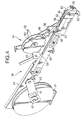
- the top surface of the base 40 serves as a guide plane 48.
- the components are fed through this guide plane 48 from the feed reel 43.
- An installation plate 49 is fixed to the side of the base 40.
- a top tape take-up reel 51 is installed through a pin 50 to this installation plate 49.
- a first feed lever 52 is rotatably installed on the side of the top tape take-up reel 51. The rotation of the first feed lever 52 is converted into the rotational motion of the top tape take-up reel 51 through a ratchet nail 53. This conversion enables the top tape to be reeled.
- An assistant plate 56 is installed above the guide plane 48 of the base 40 which is located on the side of the installation plate 49.
- An assistant lever 58 is installed through a pin 57 by this assistant plate 56.
- the controller 30 in Fig. 3 controls so as to operate the Y-axis motor 32, move the carriage 13 backward along the Y-axis rail 12, and also move the mount head 20 in the X-axis direction along the X-axis rail 19 by using the X-axis motor 31, and then move the suction nozzle 21 of the mount head 20 to a portion above the component draw position 64.
- the correction is carried out in accordance with the following equation:
- (Xn, Yn) indicates the normal suction position of the suction nozzle 21 with respect to the center of the component 72.
- the addition of such correction enables the correction for the case of the suction at the position when the suction nozzle 21 is deviated by a predetermined amount in a predetermined direction with respect to the center of the component 72.
- the mount unit in the above-mentioned embodiment has the structure in which the CCD camera is used as the component recognition camera 26.
- a line sensor using an LED as the component recognition camera 26 can attain the same functions.
- the component recognition can be attained by using a method of a non-contact sensor, an X-ray or the like.
- the mount machine using the part cassettes 39 is indicated as a component feeder. However, it can be widely applied to a component mounting apparatus using a bulk feeder cassette, a stick type component supply cassette, or a tray type component feeder.
Landscapes
- Engineering & Computer Science (AREA)
- Manufacturing & Machinery (AREA)
- Microelectronics & Electronic Packaging (AREA)
- Operations Research (AREA)
- Supply And Installment Of Electrical Components (AREA)
- Control Of Position Or Direction (AREA)
Abstract
Description



Claims (8)
- A component holding position correcting apparatus in a component mounting apparatus for holding a component with a holder and mounting the component in a predetermined position, said component holding position correcting apparatus comprising:a detector for detecting a deviation of a holding position of the holder with respect to a standard position of the component; anda controller for correcting a holding position at which said holder holds a next component, on the basis of the deviation detected by said detector.
- The component holding position correcting apparatus according to Claim 1, wherein said controller corrects the holding position, on the basis of a value in which the deviation detected by said detector is multiplied by a sensitivity coefficient.
- The component holding position correcting apparatus according to claim 1 or 2, wherein said standard position of said component is located at a substantial center of a plane held by said holder.
- The component holding position correcting apparatus according to claim 1 or 2, wherein said standard position of said component is a position deviated by a predetermined direction and length with respect to a center of a plane held by said holder.
- A component holding position correcting apparatus in a component mounting apparatus for holding a component from a component pickup position of a component feeder with an suction nozzle, and mounting said component in a predetermined position on a circuit board, said component holding position correcting apparatus comprising:a detector for detecting a deviation of a holding position of the suction nozzle with respect to a standard position of the component; anda controller for correcting a holding position at which said suction nozzle holds a next component, on the basis of the deviation detected by said detector.
- The component holding position correcting apparatus according to Claim 5, wherein said detector is an image recognition camera.
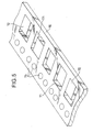
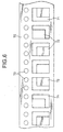
- The component holding position correcting apparatus according to claim 5 or 6, wherein components are accommodated in concave portions for component accommodation, in a one-to-one relation of a tape, and the tape is sequentially fed on said component feeder, and a component located at the component pickup position is held by said suction nozzle.
- A method of correcting a component holding position in a component mount apparatus for holding a component with a holder and mounting the component in a predetermined position, said method comprising the steps of:detecting a deviation of a holding position of the holder with respect to a standard position of the component by a detector, andcorrecting a holding position at which said holder holds a next component, on the basis of the deviation detected by the detector, by a controller.
Applications Claiming Priority (2)
| Application Number | Priority Date | Filing Date | Title |
|---|---|---|---|
| JP2000235816 | 2000-08-03 | ||
| JP2000235816A JP2002050896A (en) | 2000-08-03 | 2000-08-03 | Component gripping position correction device and correction method |
Publications (2)
| Publication Number | Publication Date |
|---|---|
| EP1178719A2 true EP1178719A2 (en) | 2002-02-06 |
| EP1178719A3 EP1178719A3 (en) | 2003-05-21 |
Family
ID=18727961
Family Applications (1)
| Application Number | Title | Priority Date | Filing Date |
|---|---|---|---|
| EP01306642A Withdrawn EP1178719A3 (en) | 2000-08-03 | 2001-08-02 | Apparatus for and method of correcting component holding position |
Country Status (5)
| Country | Link |
|---|---|
| US (1) | US6631552B2 (en) |
| EP (1) | EP1178719A3 (en) |
| JP (1) | JP2002050896A (en) |
| KR (1) | KR20020012125A (en) |
| TW (1) | TW503686B (en) |
Cited By (4)
| Publication number | Priority date | Publication date | Assignee | Title |
|---|---|---|---|---|
| EP1482775A3 (en) * | 2003-05-23 | 2007-08-29 | Hitachi High-Tech Instruments Co., Ltd. | Electronic component mounting method |
| DE102006030292A1 (en) * | 2006-06-30 | 2008-01-03 | Siemens Ag | Electronic component classification method received by holding device particularly for accurate assembly of component carrier, involves comparing two reference value of misalignment and classifying received component |
| CN107615904A (en) * | 2015-06-02 | 2018-01-19 | 富士机械制造株式会社 | Component mounting device and suction position setting method |
| EP3125666B1 (en) * | 2014-04-30 | 2019-06-12 | Yamaha Hatsudoki Kabushiki Kaisha | Electronic component mounting apparatus |
Families Citing this family (30)
| Publication number | Priority date | Publication date | Assignee | Title |
|---|---|---|---|---|
| US6571462B1 (en) * | 1999-04-27 | 2003-06-03 | Matsushita Electric Industrial Co., Ltd | Electronic component mounting apparatus using duplicate sources of components |
| EP1339098B1 (en) * | 2000-02-17 | 2009-09-02 | Panasonic Corporation | Component mounting apparatus and component mounting method |
| CN1592574B (en) * | 2003-09-01 | 2010-06-09 | 重机公司 | Adsorption position correcting device for electronic components in electronic component mounting machine |
| US7513389B2 (en) * | 2004-03-23 | 2009-04-07 | Hitachi High-Tech Instruments Co., Ltd. | Electronic component feeding device and electronic component mounting apparatus with electronic component feeding device |
| US7533459B2 (en) * | 2004-04-27 | 2009-05-19 | Hitachi High-Tech Instruments, Co., Ltd. | Electronic component mounting method and electronic component mounting apparatus |
| JP4611796B2 (en) * | 2004-04-27 | 2011-01-12 | 株式会社日立ハイテクインスツルメンツ | Electronic component mounting method and electronic component mounting apparatus |
| US9262056B2 (en) * | 2005-03-30 | 2016-02-16 | Ebay Inc. | Methods and systems to browse data items |
| JP4450772B2 (en) * | 2005-06-30 | 2010-04-14 | 株式会社日立ハイテクインスツルメンツ | Electronic component mounting device |
| JP4628205B2 (en) * | 2005-07-06 | 2011-02-09 | パナソニック株式会社 | Feedback correction method and component mounting method |
| JP4675703B2 (en) * | 2005-07-12 | 2011-04-27 | パナソニック株式会社 | How to remove parts |
| JP4686329B2 (en) * | 2005-10-18 | 2011-05-25 | Juki株式会社 | Component recognition method and apparatus |
| JP4733499B2 (en) * | 2005-10-31 | 2011-07-27 | 株式会社日立ハイテクインスツルメンツ | Electronic component mounting device |
| JP4450788B2 (en) * | 2005-11-30 | 2010-04-14 | 株式会社日立ハイテクインスツルメンツ | Electronic component mounting device |
| US8468561B2 (en) * | 2006-08-09 | 2013-06-18 | Google Inc. | Preemptible station inventory |
| US20090037302A1 (en) * | 2006-09-27 | 2009-02-05 | Rockwell Automation Technologies, Inc. | Programmatically scheduled verification |
| US20080077617A1 (en) * | 2006-09-27 | 2008-03-27 | Rockwell Automation Technologies, Inc. | Universal, hierarchical layout of assets in a facility |
| US8370224B2 (en) * | 2006-09-27 | 2013-02-05 | Rockwell Automation Technologies, Inc. | Graphical interface for display of assets in an asset management system |
| US7715930B2 (en) * | 2006-09-27 | 2010-05-11 | Rockwell Automation Technologies, Inc. | Aggregating audit information with field conditions |
| KR20080082071A (en) * | 2007-03-07 | 2008-09-11 | 삼성테크윈 주식회사 | Tape feeder |
| JP2009194543A (en) * | 2008-02-13 | 2009-08-27 | Panasonic Corp | Imaging device and manufacturing method thereof |
| JP2012019112A (en) * | 2010-07-08 | 2012-01-26 | Sony Corp | Component mounting device, component mounting method and substrate manufacturing method |
| CN104272891B (en) * | 2012-03-12 | 2018-03-16 | 麦克罗尼克迈达塔有限责任公司 | Method and apparatus for automatically storing electronic components |
| JP6404359B2 (en) * | 2014-10-03 | 2018-10-10 | 株式会社Fuji | Abnormal stop diagnosis method for component mounting system and component mounting device |
| CN107852855B (en) * | 2015-06-19 | 2020-07-03 | 雅马哈发动机株式会社 | Component mounting apparatus and component mounting method |
| WO2017130267A1 (en) * | 2016-01-25 | 2017-08-03 | 富士機械製造株式会社 | Component mounting apparatus |
| JP2017157653A (en) * | 2016-03-01 | 2017-09-07 | パナソニックIpマネジメント株式会社 | Component mounting apparatus and component mounting method |
| JP6302527B2 (en) * | 2016-10-11 | 2018-03-28 | ヤマハ発動機株式会社 | Component mounting equipment |
| JP2017017349A (en) * | 2016-10-11 | 2017-01-19 | ヤマハ発動機株式会社 | Component mounting equipment |
| US10824137B2 (en) * | 2017-06-19 | 2020-11-03 | Panasonic Intellectual Property Management Co., Ltd. | Mounting board manufacturing system |
| WO2019167845A1 (en) * | 2018-02-27 | 2019-09-06 | パナソニックIpマネジメント株式会社 | Management device, management method, and component mount system |
Family Cites Families (36)
| Publication number | Priority date | Publication date | Assignee | Title |
|---|---|---|---|---|
| DE3532500C2 (en) * | 1984-09-17 | 1996-03-14 | Tdk Corp | Pneumatically operated assembly head with suction chamber for a suction pipette |
| US5177864A (en) * | 1989-09-06 | 1993-01-12 | Matsushita Electric Industrial Co., Ltd. | Electronic component mounting apparatus and method of mounting electronic component |
| US4980971A (en) * | 1989-12-14 | 1991-01-01 | At&T Bell Laboratories | Method and apparatus for chip placement |
| US5204912A (en) * | 1990-02-26 | 1993-04-20 | Gerber Systems Corporation | Defect verification and marking system for use with printed circuit boards |
| JP2839364B2 (en) * | 1990-11-29 | 1998-12-16 | 松下電器産業株式会社 | Electronic component mounting equipment |
| JPH04291795A (en) * | 1991-03-20 | 1992-10-15 | Matsushita Electric Ind Co Ltd | Electronic part mounting unit |
| JPH0645791A (en) * | 1992-01-20 | 1994-02-18 | Tokico Ltd | Component mounting device |
| JP2911295B2 (en) * | 1992-05-15 | 1999-06-23 | 三洋電機株式会社 | Electronic component automatic mounting device |
| US5741114A (en) * | 1992-08-07 | 1998-04-21 | Yamaha Hatsudoki Kabushiki Kaisha | Method for mounting components and apparatus therefor |
| JP3077722B2 (en) * | 1992-11-10 | 2000-08-14 | ジューキ株式会社 | Electronic component positioning device |
| JP3261770B2 (en) * | 1992-11-19 | 2002-03-04 | 松下電器産業株式会社 | Component mounting device |
| JPH0715171A (en) * | 1993-06-28 | 1995-01-17 | Matsushita Electric Ind Co Ltd | Parts mounting device |
| JPH07115296A (en) * | 1993-10-15 | 1995-05-02 | Sanyo Electric Co Ltd | Controller for component mounting machine |
| KR0155748B1 (en) * | 1993-11-20 | 1998-12-15 | 김광호 | Electronic component mounting method and device |
| JPH07193397A (en) | 1993-12-27 | 1995-07-28 | Yamaha Motor Co Ltd | Mounter suction point correction device |
| JP2917826B2 (en) * | 1994-09-08 | 1999-07-12 | 日立テクノエンジニアリング株式会社 | Electronic component mounting method and mounting device |
| JPH0917809A (en) * | 1995-06-30 | 1997-01-17 | Sumitomo Kinzoku Electro Device:Kk | Method and apparatus for manufacturing semiconductor ceramic package |
| JP3132353B2 (en) * | 1995-08-24 | 2001-02-05 | 松下電器産業株式会社 | Chip mounting device and mounting method |
| KR0152879B1 (en) * | 1995-10-10 | 1998-12-15 | 이희종 | Chip recognition method and apparatus for surface mounting device |
| JP3377351B2 (en) * | 1995-12-18 | 2003-02-17 | 松下電器産業株式会社 | Electronic component mounting machine |
| JPH09186487A (en) * | 1995-12-28 | 1997-07-15 | Matsushita Electric Ind Co Ltd | Parts supply device |
| SG52900A1 (en) * | 1996-01-08 | 1998-09-28 | Matsushita Electric Industrial Co Ltd | Mounting apparatus of electronic components and mounting methods of the same |
| JP3618439B2 (en) * | 1996-01-29 | 2005-02-09 | 三星テクウィン株式会社 | Component mounting device |
| GB2310716A (en) * | 1996-02-28 | 1997-09-03 | Daewoo Electronics Co Ltd | Recognition of a fiducial mark on a printed circuit board |
| JP3397051B2 (en) * | 1996-08-20 | 2003-04-14 | 松下電器産業株式会社 | Apparatus and method for mounting conductive ball |
| US5768759A (en) * | 1996-11-19 | 1998-06-23 | Zevatech, Inc. | Method and apparatus for reflective in-flight component registration |
| JP3245081B2 (en) * | 1997-02-04 | 2002-01-07 | 松下電器産業株式会社 | Electronic component mounting machine |
| US6266873B1 (en) * | 1997-02-17 | 2001-07-31 | Matsushita Electric Industrial Co., Ltd. | Method and apparatus for mounting electronic components |
| JPH10335899A (en) * | 1997-05-29 | 1998-12-18 | Matsushita Electric Ind Co Ltd | Electronic component mounting method and electronic component mounting device |
| JPH11168297A (en) * | 1997-12-04 | 1999-06-22 | Matsushita Electric Ind Co Ltd | Judgment method and correction method of work position in work machine, work machine using them |
| JP4303345B2 (en) * | 1998-03-12 | 2009-07-29 | Juki株式会社 | Surface mount component mounting machine |
| JP2000031693A (en) * | 1998-07-10 | 2000-01-28 | Sanyo Electric Co Ltd | Electronic component sucking part teaching apparatus |
| JP3562325B2 (en) * | 1998-07-16 | 2004-09-08 | 松下電器産業株式会社 | Electronic component mounting method |
| US6195165B1 (en) * | 1998-08-04 | 2001-02-27 | Cyberoptics Corporation | Enhanced sensor |
| JP4428865B2 (en) * | 1998-10-30 | 2010-03-10 | サイバーオプティクス コーポレーション | Improved method and apparatus for controlling glint in a multi-nozzle alignment sensor |
| JP2001044696A (en) * | 1999-08-03 | 2001-02-16 | Matsushita Electric Ind Co Ltd | Electronic component mounting method |
-
2000
- 2000-08-03 JP JP2000235816A patent/JP2002050896A/en not_active Abandoned
-
2001
- 2001-07-23 TW TW090117901A patent/TW503686B/en active
- 2001-07-25 KR KR1020010044886A patent/KR20020012125A/en not_active Ceased
- 2001-08-01 US US09/918,455 patent/US6631552B2/en not_active Expired - Fee Related
- 2001-08-02 EP EP01306642A patent/EP1178719A3/en not_active Withdrawn
Cited By (7)
| Publication number | Priority date | Publication date | Assignee | Title |
|---|---|---|---|---|
| EP1482775A3 (en) * | 2003-05-23 | 2007-08-29 | Hitachi High-Tech Instruments Co., Ltd. | Electronic component mounting method |
| DE102006030292A1 (en) * | 2006-06-30 | 2008-01-03 | Siemens Ag | Electronic component classification method received by holding device particularly for accurate assembly of component carrier, involves comparing two reference value of misalignment and classifying received component |
| EP3125666B1 (en) * | 2014-04-30 | 2019-06-12 | Yamaha Hatsudoki Kabushiki Kaisha | Electronic component mounting apparatus |
| CN107615904A (en) * | 2015-06-02 | 2018-01-19 | 富士机械制造株式会社 | Component mounting device and suction position setting method |
| EP3307039A4 (en) * | 2015-06-02 | 2018-05-30 | Fuji Machine Mfg. Co., Ltd. | Component mounting device and suction position setting method |
| CN107615904B (en) * | 2015-06-02 | 2019-10-08 | 株式会社富士 | Component mounting device and suction position setting method |
| US10750648B2 (en) | 2015-06-02 | 2020-08-18 | Fuji Corporation | Component mounting apparatus and suction position setting method |
Also Published As
| Publication number | Publication date |
|---|---|
| US20020056188A1 (en) | 2002-05-16 |
| TW503686B (en) | 2002-09-21 |
| JP2002050896A (en) | 2002-02-15 |
| EP1178719A3 (en) | 2003-05-21 |
| KR20020012125A (en) | 2002-02-15 |
| US6631552B2 (en) | 2003-10-14 |
Similar Documents
| Publication | Publication Date | Title |
|---|---|---|
| US6631552B2 (en) | Apparatus for and method of correcting component holding position | |
| EP0660657B1 (en) | Method and mounting device for mounting a component at a specific position | |
| US6526651B1 (en) | Printed circuit board transferring apparatus of a surface mounter | |
| KR910003000B1 (en) | Electronic component mounting device | |
| JP5174583B2 (en) | Control method of electronic component mounting apparatus | |
| JP6224348B2 (en) | Judgment device, surface mounter | |
| JP3523480B2 (en) | Camera position correction device | |
| US8701275B2 (en) | Surface mounting apparatus | |
| US20210029857A1 (en) | Component mounting device, method of capturing image, and method of determining mounting sequence | |
| JP2005347412A (en) | Adsorption state inspection device, surface mounter, and component testing device | |
| JP2942364B2 (en) | Component mounting device | |
| KR101050840B1 (en) | Component mounting machine and its electronic component pickup mounting method | |
| JPH08181493A (en) | Parts mounting method and device | |
| JP2554424B2 (en) | Parts mounting device | |
| JP3564191B2 (en) | Positioning method and device for mounting machine | |
| JP3860919B2 (en) | Component recognition mounting apparatus and component recognition method | |
| JP3397127B2 (en) | Electronic component mounting apparatus and mounting method | |
| KR100651789B1 (en) | Component mounting device and component mounting method | |
| JP3142720B2 (en) | Positioning method and device for mounting machine | |
| JP2006073959A (en) | Component recognition device, surface mounter and component testing device | |
| JP3445681B2 (en) | Chip mounter | |
| JP7787036B2 (en) | Parts Mounting Equipment | |
| JP7811728B2 (en) | Component mounting device and component mounting method | |
| JP2000124696A (en) | Method and apparatus for detecting displacement of component recognition reference in mounting machine | |
| JP3726585B2 (en) | Electronic component mounting method |
Legal Events
| Date | Code | Title | Description |
|---|---|---|---|
| PUAI | Public reference made under article 153(3) epc to a published international application that has entered the european phase |
Free format text: ORIGINAL CODE: 0009012 |
|
| AK | Designated contracting states |
Kind code of ref document: A2 Designated state(s): AT BE CH CY DE DK ES FI FR GB GR IE IT LI LU MC NL PT SE TR |
|
| AX | Request for extension of the european patent |
Free format text: AL;LT;LV;MK;RO;SI |
|
| PUAL | Search report despatched |
Free format text: ORIGINAL CODE: 0009013 |
|
| AK | Designated contracting states |
Designated state(s): AT BE CH CY DE DK ES FI FR GB GR IE IT LI LU MC NL PT SE TR |
|
| AX | Request for extension of the european patent |
Extension state: AL LT LV MK RO SI |
|
| 17P | Request for examination filed |
Effective date: 20031023 |
|
| STAA | Information on the status of an ep patent application or granted ep patent |
Free format text: STATUS: THE APPLICATION HAS BEEN WITHDRAWN |
|
| AKX | Designation fees paid |
Designated state(s): DE GB |
|
| 18W | Application withdrawn |
Effective date: 20040102 |