EP1177708B2 - Ameliorations apportees a des elements chauffants, notamment dans le domaine des elements chauffants en couche epaisse - Google Patents
Ameliorations apportees a des elements chauffants, notamment dans le domaine des elements chauffants en couche epaisse Download PDFInfo
- Publication number
- EP1177708B2 EP1177708B2 EP00927490A EP00927490A EP1177708B2 EP 1177708 B2 EP1177708 B2 EP 1177708B2 EP 00927490 A EP00927490 A EP 00927490A EP 00927490 A EP00927490 A EP 00927490A EP 1177708 B2 EP1177708 B2 EP 1177708B2
- Authority
- EP
- European Patent Office
- Prior art keywords
- heating element
- thick film
- element assembly
- heated
- assembly
- Prior art date
- Legal status (The legal status is an assumption and is not a legal conclusion. Google has not performed a legal analysis and makes no representation as to the accuracy of the status listed.)
- Expired - Lifetime
Links
Images
Classifications
-
- H—ELECTRICITY
- H05—ELECTRIC TECHNIQUES NOT OTHERWISE PROVIDED FOR
- H05B—ELECTRIC HEATING; ELECTRIC LIGHT SOURCES NOT OTHERWISE PROVIDED FOR; CIRCUIT ARRANGEMENTS FOR ELECTRIC LIGHT SOURCES, IN GENERAL
- H05B3/00—Ohmic-resistance heating
- H05B3/78—Heating arrangements specially adapted for immersion heating
- H05B3/82—Fixedly-mounted immersion heaters
-
- H—ELECTRICITY
- H05—ELECTRIC TECHNIQUES NOT OTHERWISE PROVIDED FOR
- H05B—ELECTRIC HEATING; ELECTRIC LIGHT SOURCES NOT OTHERWISE PROVIDED FOR; CIRCUIT ARRANGEMENTS FOR ELECTRIC LIGHT SOURCES, IN GENERAL
- H05B3/00—Ohmic-resistance heating
- H05B3/20—Heating elements having extended surface area substantially in a two-dimensional plane, e.g. plate-heater
- H05B3/22—Heating elements having extended surface area substantially in a two-dimensional plane, e.g. plate-heater non-flexible
- H05B3/26—Heating elements having extended surface area substantially in a two-dimensional plane, e.g. plate-heater non-flexible heating conductor mounted on insulating base
- H05B3/262—Heating elements having extended surface area substantially in a two-dimensional plane, e.g. plate-heater non-flexible heating conductor mounted on insulating base the insulating base being an insulated metal plate
-
- H—ELECTRICITY
- H05—ELECTRIC TECHNIQUES NOT OTHERWISE PROVIDED FOR
- H05B—ELECTRIC HEATING; ELECTRIC LIGHT SOURCES NOT OTHERWISE PROVIDED FOR; CIRCUIT ARRANGEMENTS FOR ELECTRIC LIGHT SOURCES, IN GENERAL
- H05B3/00—Ohmic-resistance heating
- H05B3/78—Heating arrangements specially adapted for immersion heating
-
- H—ELECTRICITY
- H05—ELECTRIC TECHNIQUES NOT OTHERWISE PROVIDED FOR
- H05B—ELECTRIC HEATING; ELECTRIC LIGHT SOURCES NOT OTHERWISE PROVIDED FOR; CIRCUIT ARRANGEMENTS FOR ELECTRIC LIGHT SOURCES, IN GENERAL
- H05B2203/00—Aspects relating to Ohmic resistive heating covered by group H05B3/00
- H05B2203/013—Heaters using resistive films or coatings
-
- H—ELECTRICITY
- H05—ELECTRIC TECHNIQUES NOT OTHERWISE PROVIDED FOR
- H05B—ELECTRIC HEATING; ELECTRIC LIGHT SOURCES NOT OTHERWISE PROVIDED FOR; CIRCUIT ARRANGEMENTS FOR ELECTRIC LIGHT SOURCES, IN GENERAL
- H05B2203/00—Aspects relating to Ohmic resistive heating covered by group H05B3/00
- H05B2203/017—Manufacturing methods or apparatus for heaters
Definitions
- This invention concerns improvements relating to electric heating elements and, more particularly, concerns heating elements of the so-called thick film type comprising a substrate, commonly formed of stainless steel, carrying a resistance heating track or layer which, as appropriate having regard to the nature of the substrate, may be formed on an electrically-insulating layer, commonly of glass, provided on the substrate. An additional electrically-insulating layer may be provided over the resistance heating track or layer as a protective measure.
- Thick film heating elements are employed in a variety of applications and are currently becoming popular in the field of electrically-heated water boiling vessels, domestic kettles and hot water jugs for example, where their clean appearance as compared to the conventional immersion heating element of metal sheathed construction has aesthetic advantages.
- a thick film heating element to accommodate a greater power density than is readily accommodated with conventional sheathed heating elements, leading to more rapid boiling times.
- thick film heating elements are commonly formed on a stainless steel substrate, for example by first providing an electrically-insulating layer of glass on one or both surfaces of a stainless steel plate or disc and then screen-printing a resistance heating track onto the glass surface using electrically conductive inks which are then fired. As abovementioned, a further layer of glass may then be provided over the resistive track.
- International PCT Patent Application No. WO 96/17496 discloses one such element that comprises, as aforementioned, a stainless steel substrate that is overlaid with an electrically insulating layer, a resistive heating track, and finally with a further insulating layer.
- the invention of our British Patent Application No. 2349322 proposed to form the substrate of a thick film heating element with a slightly domed curvature, form the heating element track or layer on the convex surface of the domed substrate, and bond the thus formed thick film heating element to a planar surface to be heated by a process which flattens the domed thick film heating element onto the planar surface.
- any material may be used for the intermediate heat dispersion layer, provided it has a thermal conductivity significantly greater than the stainless steels used, i.e. about 20W/sqM/°C.
- Preferred materials are copper and aluminium, chosen for their thermal conductivity, relatively low cost and compatibility with the proposed assembly processes.
- the joining process may be the same as or similar to any of the existing known methods of attaching aluminium mounting plates as for Blitzkocher type elements, i.e. impact pressure bonding, welding or brazing, with any of the known sources of heat.
- the preferred method because of its controllability, is induction brazing.
- This technique claims to give a good quality, repeatable, joint with few voids.
- the join of the heat dispersion layer to the vessel may be done first, for example by impact bonding, and the heating element may be induction brazed separately, giving the opportunity of inspecting the quality of the vessel/dispersion layer joint. Vents could be left in the part of the dispersion layer which extends beyond the heating element to allow the escape of flux and fumes generated during brazing.
- the assembly is desirably pressed together with a clamping force, possibly as much as 4 tons, to ensure that the plates are flattened together without any gaps in the joint area.
- a clamping force possibly as much as 4 tons
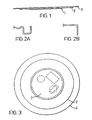
- the illustrated embodiment comprises a thick film heating element 1 of relatively small diameter which is bonded to a heat dispersion plate 2, formed of aluminium or copper for example and having a diameter greater than that of the thick film heating element 1, which in turn is bonded to a heating surface 3 shown in the example as a thin metal plate adapted to be fitted into the bottom of a water heating appliance, the alternative edge details shown in Figures 2A and 2B are, respectively, intended to provide a water-retaining well around the heating element periphery to facilitate sealing of the element into a vessel body by providing a cooler sealing environment and to facilitate interfacing with the vessel body; other edge configurations are of course possible.
- a thick film heating element having a power density of more than 30W/cm 2 will give rise to unacceptable noise. This equates to an overall power output of about 3kW on an element formed on a 120mm diameter disc with a plain sealing area left all round. It is proposed according to the teachings of the present invention to use a significantly higher power density heating element formed on a disc of around 60mm, for example. It is proposed that the dispersion layer will spread the heat over an area extending about 10mm beyond the disc, thus giving a heating element of an effective diameter of 80mm. Bearing in mind that the material costs of a thick film heating element are proportion to its area (thickness being constant), a conventional 80mm diameter element would use 78% more material than one of 60mm diameter constructed according to the present invention, which represents a significant saving.
- the dispersion layer taught by the present invention heat can flow laterally as well as transversely, so that a more uniform heat distribution is obtained on the liquid heating surface.
- the power density on the liquid heating surface is close to the calculated value of the power divided by the surface area, rather than to the value of the power divided by the (much smaller) heater track area. The result is a lower effective power density and a significant reduction in noise generated.
- the following values are taken from present production elements.
- the heater track power density is 68W/cm 2 .
- the area of the heater could be reduced to less than half, whilst maintaining the same power density on the liquid heating surface.
- the heater can be reduced still further in size. The net result of this is a major reduction in the cost of the materials of the element.
- a disc of 77mm diameter has half the area of one of 110mm, and taking into account the dispersion layer, this gives an element diameter of approximately 60mm, the value used in the example above.
- substrates of between 1.2 and 1.5mm are used to achieve satisfactory mechanical rigidity and resistance to thermal and mechanical shock.
- reduce the substrate thickness for example to 0.3mm, to allow the use of high power density without a penalty in increased track running temperatures.
- the improved heat transfer efficiency afforded by the dispersion layer will reduce the track running temperature to acceptable values, but this will only be possible by reducing the thermal resistance of the whole sandwich to values similar to those at present, taking into account the narrow thermal path of the present designs.
- the thin substrate becomes possible because of the support and cushioning of the dispersion layer, further supported by the water treating plate and/or vessel wall.
- the complete assembly will be able to withstand mechanical impact and thermal shock better than an element with a unitary substrate of the present thickness.
- the vessel wall which is preferably formed of a 300 series stainless steel commonly used in stainless steel cooking vessels like saucepans, is also reduced to around 0.3mm. This compares with 0.5mm normally found in stainless steel kettles.
- the arrangement of the sandwich is preferably such that the thermal resistance between the printed heater tracks and the heating surface is not more than that of a conventionally made thick film heating element on a 1.2mm substrate of 400 series (S430D or S444) stainless steel, with a dielectric thickness of no more than 100 ⁇ .
- the complete heating element sandwich can be made as an "Easifix” ( GB 2330064A ) type element or as a Strix "Sure Seal” ( WO 96/18331 ) for fitting to a moulded vessel, or it may be made directly onto the base of a stainless steel vessel.
- This latter option is a very cost effective method of fitting a thick film heater to a stainless steel appliance, something that, so far as we are aware, has only been done by Pifco - Russell Hobbs by using the same (costly) plastic securing ring as was developed for the Millennium kettle. Examples of such mountings are in Pifco's GB 2 291 324 and GB 2 319 154 which show the complexity of the method.
- a further advantage of the small element proposed by the present invention which gives rise to savings in the manufacturing cost of the elements, is that they may be processed several at a time.
- the number of elements which can be printed simultaneously is limited by the area of the screen printer and by the width of the processing ovens.
- the diameter of the element four times as many may be printed and processed together on the same equipment. Depending on the type of equipment used, this may be achieved by carrying the elements in a strip and separating them on completion, or by automated handling, placing individual discs into location jigs for printing and onto the oven belts for drying and firing. It is believed that retaining the discs in a strip for processing will lead to reduced distortion, as a result of the support of the strip. In any case, measures such as this may be desirable to reduce the effects of distortion.
- the small diameter element has an additional operational advantage, in that it is less sensitive to being operated on a slope whilst heating liquids.
- the dispersion layer will ensure that, as liquid boils away, the exposed area of the heater is cooled to some extent by the remaining liquid until a protector can operate.
- any thermal protector will tend to cover a larger proportion of the heating element and give protection over a wider area.
- the proposal of the invention may be considered to be similar in principle to the Blitzkocher type of heating element construction, where a sheathed heating element is secured to a heat transfer plate which in turn is secured to a steel plate which is part of a liquid heating vessel.
- the power density available from a sheathed heating element is limited by the insulation of the mineral filling of the sheath and by the robustness of the joint between the sheath and the heat dispersion material. If the power density of a Blitzkocher heating element is too great, the thermal expansion of the sheath causes it to peel away from its support, leading to further overheating and subsequent premature failure.
Landscapes
- Cookers (AREA)
- Resistance Heating (AREA)
Claims (21)
- Ensemble d'élément chauffant comprenant un élément chauffant (1), d'une structure à film épais et comprenant un substrat, fixé contre une surface à chauffer (3), caractérisé en ce qu'une couche de dispersion de la chaleur à haute conductivité thermique (2) est prévue entre l'élément chauffant (1) et la surface à chauffer (3), la couche de dispersion de la chaleur (2) s'étendant latéralement au-delà de la périphérie de l'élément chauffant (1).
- Ensemble d'élément chauffant selon la revendication 1, dans lequel le substrat est en acier inoxydable.
- Ensemble d'élément chauffant selon la revendication 2, dans lequel ledit substrat a une épaisseur de moins de 0,5 mm.
- Ensemble d'élément chauffant selon l'une quelconque des revendications précédentes, dans lequel ladite couche de dispersion de la chaleur (2) comprend du cuivre ou de l'aluminium.
- Ensemble d'élément chauffant selon l'une quelconque des revendications précédentes, dans lequel la densité de puissance de l'élément chauffant à film épais (1), mesurée sur sa superficie totale, est sensiblement supérieure à 30 W/cm2.
- Ensemble d'élément chauffant selon la revendication 5, dans lequel la densité de puissance de l'élément chauffant à film épais (1), mesurée sur sa superficie totale, est d'au moins 60 W/cm2.
- Ensemble d'élément chauffant selon l'une quelconque des revendications précédentes, dans lequel la superficie de l'élément chauffant à film épais (1) est de l'ordre d'un tiers à la moitié de la superficie de la surface à chauffer.
- Ensemble d'élément chauffant selon la revendication 7, dans lequel la surface à chauffer (3) est un disque d'un diamètre d'environ 100 ou 110 mm et l'élément chauffant à film épais (1) est un disque d'un diamètre d'environ 60 à 80 mm.
- Ensemble d'élément chauffant selon l'une quelconque des revendications précédentes, dans lequel la couche de dispersion de la chaleur (2) s'étend à au moins 10 mm au-delà de la périphérie de l'élément chauffant à film épais (1).
- Ensemble d'élément chauffant selon l'une quelconque des revendications précédentes, dans lequel la surface à chauffer (3) comprend une plaque chauffante conçue pour être assemblée dans un récipient de chauffage pour liquides doté d'un corps en plastique.
- Ensemble d'élément chauffant selon la revendication 10, dans lequel la plaque chauffante est conçue avec une cavité autour de sa périphérie.
- Ensemble d'élément chauffant selon l'une quelconque des revendications 1 à 9, dans lequel la surface à chauffer (3) comprend le fond d'un récipient de chauffage pour liquides.
- Ensemble d'élément chauffant selon la revendication 12, dans lequel ledit fond du récipient de chauffage pour liquides est conçu en acier inoxydable.
- Ensemble d'élément chauffant selon la revendication 13, dans lequel le fond du récipient de chauffage est conçu en acier inoxydable série 300.
- Ensemble d'élément chauffant selon la revendication 13 ou 14, dans lequel ledit acier inoxydable a une épaisseur de moins de 0,5 mm, de préférence 0,3 mm.
- Ensemble d'élément chauffant selon l'une quelconque des revendications 10 à 15, dans lequel la surface à chauffer (3), vue du côté contre lequel est fixé l'élément chauffant à film épais, présente un creux dans lequel est fixé l'élément chauffant à film épais.
- Ensemble chauffant selon la revendication 1, dans lequel l'élément chauffant à film épais (1) fournit une sortie ayant une densité de puissance prédéterminée et la couche de dispersion de la chaleur (2) doit avoir pour effet de conférer à l'ensemble global une densité de puissance qui est sensiblement inférieure à celle de l'élément chauffant à film épais (1) lui-même.
- Récipient de chauffage pour liquides comprenant un ensemble d'élément chauffant selon la revendication 1, dans lequel ledit élément chauffant à film épais (1) est nettement plus petit que ladite surface à chauffer (3), et ladite couche de dispersion de la chaleur (2) est nettement plus grande que ledit élément chauffant à film épais (1).
- Récipient de chauffage pour liquides selon la revendication 18, dans lequel ledit élément chauffant à film épais a un diamètre qui est inférieur à la moitié du diamètre de ladite surface à chauffer.
- Récipient de chauffage pour liquides selon la revendication 18 ou 19, dans lequel ladite couche de dispersion de la chaleur a un diamètre qui mesure près du double du diamètre dudit élément chauffant à film épais.
- Récipient de chauffage pour liquides comprenant un ensemble d'élément chauffant (1, 2, 3) selon l'une quelconque des revendications 1 à 17.
Priority Applications (1)
| Application Number | Priority Date | Filing Date | Title |
|---|---|---|---|
| DE60024253T DE60024253T3 (de) | 1999-05-04 | 2000-05-04 | Verbesserungen für heizelemente, insbesondere für dickschichtheizelemente |
Applications Claiming Priority (3)
| Application Number | Priority Date | Filing Date | Title |
|---|---|---|---|
| GB9910286A GB2351894B (en) | 1999-05-04 | 1999-05-04 | Improvements relating to heating elements |
| GB9910286 | 1999-05-04 | ||
| PCT/GB2000/001695 WO2000067527A1 (fr) | 1999-05-04 | 2000-05-04 | Ameliorations apportees a des elements chauffants, notamment dans le domaine des elements chauffants en couche epaisse |
Publications (3)
| Publication Number | Publication Date |
|---|---|
| EP1177708A1 EP1177708A1 (fr) | 2002-02-06 |
| EP1177708B1 EP1177708B1 (fr) | 2005-11-23 |
| EP1177708B2 true EP1177708B2 (fr) | 2012-12-12 |
Family
ID=10852772
Family Applications (1)
| Application Number | Title | Priority Date | Filing Date |
|---|---|---|---|
| EP00927490A Expired - Lifetime EP1177708B2 (fr) | 1999-05-04 | 2000-05-04 | Ameliorations apportees a des elements chauffants, notamment dans le domaine des elements chauffants en couche epaisse |
Country Status (6)
| Country | Link |
|---|---|
| EP (1) | EP1177708B2 (fr) |
| CN (1) | CN1162044C (fr) |
| AT (1) | ATE311083T1 (fr) |
| DE (1) | DE60024253T3 (fr) |
| GB (1) | GB2351894B (fr) |
| WO (1) | WO2000067527A1 (fr) |
Families Citing this family (15)
| Publication number | Priority date | Publication date | Assignee | Title |
|---|---|---|---|---|
| US8680443B2 (en) | 2004-01-06 | 2014-03-25 | Watlow Electric Manufacturing Company | Combined material layering technologies for electric heaters |
| GB2481217B (en) | 2010-06-15 | 2017-06-07 | Otter Controls Ltd | Thick film heaters |
| TWI503903B (zh) * | 2011-10-26 | 2015-10-11 | 矽品精密工業股份有限公司 | 打線機台之加熱治具 |
| WO2015161120A1 (fr) * | 2014-04-16 | 2015-10-22 | Spectrum Brands, Inc. | Système de récipient portable pour chauffer une boisson |
| EP3132654A4 (fr) | 2014-04-16 | 2018-01-31 | Spectrum Brands, Inc. | Appareil de cuisson utilisant un élément chauffant à film mince |
| ES2751548T3 (es) * | 2015-09-21 | 2020-04-01 | Ego Elektro Geraetebau Gmbh | Dispositivo de calefacción para calentar agua y método para la operación de dicho dispositivo de calefacción |
| CN106686773B (zh) * | 2016-01-06 | 2019-09-10 | 黄伟聪 | 一种双面高导热能力的厚膜发热元件 |
| CN106686770B (zh) * | 2016-02-03 | 2019-09-10 | 黄伟聪 | 一种涂覆基质具有高导热能力的厚膜元件 |
| CN106686771B (zh) * | 2016-02-03 | 2019-09-06 | 黄伟聪 | 一种覆盖层具有高导热能力的厚膜元件 |
| DE102016125678A1 (de) * | 2016-12-23 | 2018-06-28 | Vorwerk & Co. Interholding Gmbh | Heizelement für eine Küchenmaschine, Küchenmaschine, Kochgefäß sowie Verfahren zur Herstellung eines Heizelementes |
| CN108261068B (zh) * | 2016-12-30 | 2021-06-01 | 佛山市顺德区美的电热电器制造有限公司 | 电水壶 |
| CN108784334B (zh) * | 2017-04-26 | 2021-04-20 | 佛山市顺德区美的电热电器制造有限公司 | 电水壶 |
| WO2019080590A1 (fr) * | 2017-10-27 | 2019-05-02 | 佛山市顺德区美的电热电器制造有限公司 | Ensemble récipient interne et dispositif de chauffage de liquide |
| CN109717735B (zh) * | 2017-10-27 | 2021-03-19 | 佛山市顺德区美的电热电器制造有限公司 | 内胆组件以及液体加热器 |
| FR3088413B1 (fr) * | 2018-11-09 | 2020-12-18 | Rosinox | Systeme de chauffe et appareil de cuisson le comportant |
Citations (7)
| Publication number | Priority date | Publication date | Assignee | Title |
|---|---|---|---|---|
| EP0229928A2 (fr) † | 1985-12-20 | 1987-07-29 | Bosch-Siemens HausgerÀ¤te GmbH | Elément de chauffage pour appareils de chauffage notamment pour cuisinières |
| DE3625087A1 (de) † | 1986-07-24 | 1988-01-28 | Ego Elektro Blanc & Fischer | Elektro-bauelement |
| EP0574310A1 (fr) † | 1992-06-11 | 1993-12-15 | Seb S.A. | Plaque chauffante pour récipient chauffant, notamment pour bouilloire |
| EP0585015A1 (fr) † | 1992-08-13 | 1994-03-02 | Pifco Limited | Dispositif à chauffer des liquides |
| WO1996018331A1 (fr) † | 1994-12-13 | 1996-06-20 | Strix Limited | Recipients de chauffage de liquide |
| WO1997014269A1 (fr) † | 1995-10-11 | 1997-04-17 | Strix Limited | Dispositifs de chauffage electriques |
| EP0885579A1 (fr) † | 1997-06-16 | 1998-12-23 | E.G.O. ELEKTRO-GERÄTEBAU GmbH | Elément de paroi |
Family Cites Families (8)
| Publication number | Priority date | Publication date | Assignee | Title |
|---|---|---|---|---|
| GB1407201A (en) * | 1971-06-23 | 1975-09-24 | Lucas Electrical Co Ltd | Printed electric wiring arrangements |
| US4063068A (en) * | 1976-08-12 | 1977-12-13 | Minnesota Mining And Manufacturing Company | Food heating and cooking receptacle |
| GB8605948D0 (en) * | 1986-03-11 | 1986-04-16 | Thorn Emi Appliances | Cooking hob |
| AT408299B (de) * | 1994-03-30 | 2001-10-25 | Electrovac | Heizvorrichtung für elektrische heizplatten, zündeinrichtungen, temperatursensoren od. dgl. |
| GB9423901D0 (en) * | 1994-11-26 | 1995-01-11 | Pifco Ltd | Improvements to thick film elements |
| US5657532A (en) * | 1996-01-16 | 1997-08-19 | Ferro Corporation | Method of making insulated electrical heating element using LTCC tape |
| GB2316848B (en) * | 1996-08-27 | 2000-10-04 | Strix Ltd | Electric heaters |
| GB9716561D0 (en) * | 1997-08-05 | 1997-10-08 | Strix Ltd | Electric heaters |
-
1999
- 1999-05-04 GB GB9910286A patent/GB2351894B/en not_active Expired - Fee Related
-
2000
- 2000-05-04 AT AT00927490T patent/ATE311083T1/de not_active IP Right Cessation
- 2000-05-04 WO PCT/GB2000/001695 patent/WO2000067527A1/fr active IP Right Grant
- 2000-05-04 EP EP00927490A patent/EP1177708B2/fr not_active Expired - Lifetime
- 2000-05-04 CN CNB008095507A patent/CN1162044C/zh not_active Expired - Fee Related
- 2000-05-04 DE DE60024253T patent/DE60024253T3/de not_active Expired - Lifetime
Patent Citations (7)
| Publication number | Priority date | Publication date | Assignee | Title |
|---|---|---|---|---|
| EP0229928A2 (fr) † | 1985-12-20 | 1987-07-29 | Bosch-Siemens HausgerÀ¤te GmbH | Elément de chauffage pour appareils de chauffage notamment pour cuisinières |
| DE3625087A1 (de) † | 1986-07-24 | 1988-01-28 | Ego Elektro Blanc & Fischer | Elektro-bauelement |
| EP0574310A1 (fr) † | 1992-06-11 | 1993-12-15 | Seb S.A. | Plaque chauffante pour récipient chauffant, notamment pour bouilloire |
| EP0585015A1 (fr) † | 1992-08-13 | 1994-03-02 | Pifco Limited | Dispositif à chauffer des liquides |
| WO1996018331A1 (fr) † | 1994-12-13 | 1996-06-20 | Strix Limited | Recipients de chauffage de liquide |
| WO1997014269A1 (fr) † | 1995-10-11 | 1997-04-17 | Strix Limited | Dispositifs de chauffage electriques |
| EP0885579A1 (fr) † | 1997-06-16 | 1998-12-23 | E.G.O. ELEKTRO-GERÄTEBAU GmbH | Elément de paroi |
Also Published As
| Publication number | Publication date |
|---|---|
| GB2351894B (en) | 2003-10-15 |
| CN1162044C (zh) | 2004-08-11 |
| WO2000067527A1 (fr) | 2000-11-09 |
| DE60024253D1 (de) | 2005-12-29 |
| EP1177708A1 (fr) | 2002-02-06 |
| ATE311083T1 (de) | 2005-12-15 |
| EP1177708B1 (fr) | 2005-11-23 |
| GB9910286D0 (en) | 1999-06-30 |
| DE60024253T2 (de) | 2006-08-24 |
| GB2351894A (en) | 2001-01-10 |
| CN1358402A (zh) | 2002-07-10 |
| DE60024253T3 (de) | 2013-05-29 |
Similar Documents
| Publication | Publication Date | Title |
|---|---|---|
| EP1177708B2 (fr) | Ameliorations apportees a des elements chauffants, notamment dans le domaine des elements chauffants en couche epaisse | |
| US3622754A (en) | Glass plate surface heating unit with even temperature distribution | |
| EP0830803B1 (fr) | Elements de chauffage electriques | |
| JP3894577B2 (ja) | 加熱要素 | |
| EP0743833B2 (fr) | Recipients de chauffage de liquide | |
| EP0916234B1 (fr) | Element chauffant | |
| EP3056062B1 (fr) | Element chauffant a couche epaisse et equipement de cuisine comportant un tel element | |
| WO1999030536A1 (fr) | Thermoplongeur | |
| CN101396228A (zh) | 电磁加热专用陶瓷容器 | |
| WO1999008485A9 (fr) | Recipients electriques de chauffage de liquide | |
| GB2369037A (en) | Appliances for heating liquids and foodstuffs | |
| GB2230852A (en) | Cooking hob | |
| CN100544610C (zh) | 一种煮煲仔饭的装置 | |
| US20100224618A1 (en) | Electric heating container and electric heating method | |
| CN208973487U (zh) | 一种具有检测异物功能的发热盘 | |
| KR100805380B1 (ko) | 면상발열체를 이용한 전기쿡탑 | |
| CN217875960U (zh) | 一种便于温度传感装置接线的面板及电磁烹饪器具 | |
| KR102552263B1 (ko) | 측면가열 관통형 조리기기 | |
| CN217875968U (zh) | 一种温度传感装置与面板的安装结构及使用它的烹饪器具 | |
| CN217952382U (zh) | 一种快速感温面板的温度传感装置安装结构及烹饪器具 | |
| CN219264375U (zh) | 电磁感应加热器具 | |
| JP2003339547A (ja) | 誘導加熱調理器用加熱プレート及び鍋 | |
| GB2349322A (en) | Reducing stress in thick film heating element assemblies | |
| JPH0632010Y2 (ja) | 電気調理器具 | |
| CN201332968Y (zh) | 一种可导磁锅具 |
Legal Events
| Date | Code | Title | Description |
|---|---|---|---|
| PUAI | Public reference made under article 153(3) epc to a published international application that has entered the european phase |
Free format text: ORIGINAL CODE: 0009012 |
|
| 17P | Request for examination filed |
Effective date: 20011129 |
|
| AK | Designated contracting states |
Kind code of ref document: A1 Designated state(s): AT BE CH CY DE DK ES FI FR GB GR IE IT LI LU MC NL PT SE |
|
| 17Q | First examination report despatched |
Effective date: 20031031 |
|
| GRAP | Despatch of communication of intention to grant a patent |
Free format text: ORIGINAL CODE: EPIDOSNIGR1 |
|
| GRAS | Grant fee paid |
Free format text: ORIGINAL CODE: EPIDOSNIGR3 |
|
| GRAA | (expected) grant |
Free format text: ORIGINAL CODE: 0009210 |
|
| AK | Designated contracting states |
Kind code of ref document: B1 Designated state(s): AT BE CH CY DE DK ES FI FR GB GR IE IT LI LU MC NL PT SE |
|
| PG25 | Lapsed in a contracting state [announced via postgrant information from national office to epo] |
Ref country code: IT Free format text: LAPSE BECAUSE OF FAILURE TO SUBMIT A TRANSLATION OF THE DESCRIPTION OR TO PAY THE FEE WITHIN THE PRESCRIBED TIME-LIMIT;WARNING: LAPSES OF ITALIAN PATENTS WITH EFFECTIVE DATE BEFORE 2007 MAY HAVE OCCURRED AT ANY TIME BEFORE 2007. THE CORRECT EFFECTIVE DATE MAY BE DIFFERENT FROM THE ONE RECORDED. Effective date: 20051123 Ref country code: LI Free format text: LAPSE BECAUSE OF FAILURE TO SUBMIT A TRANSLATION OF THE DESCRIPTION OR TO PAY THE FEE WITHIN THE PRESCRIBED TIME-LIMIT Effective date: 20051123 Ref country code: FI Free format text: LAPSE BECAUSE OF FAILURE TO SUBMIT A TRANSLATION OF THE DESCRIPTION OR TO PAY THE FEE WITHIN THE PRESCRIBED TIME-LIMIT Effective date: 20051123 Ref country code: BE Free format text: LAPSE BECAUSE OF FAILURE TO SUBMIT A TRANSLATION OF THE DESCRIPTION OR TO PAY THE FEE WITHIN THE PRESCRIBED TIME-LIMIT Effective date: 20051123 Ref country code: CH Free format text: LAPSE BECAUSE OF FAILURE TO SUBMIT A TRANSLATION OF THE DESCRIPTION OR TO PAY THE FEE WITHIN THE PRESCRIBED TIME-LIMIT Effective date: 20051123 Ref country code: AT Free format text: LAPSE BECAUSE OF FAILURE TO SUBMIT A TRANSLATION OF THE DESCRIPTION OR TO PAY THE FEE WITHIN THE PRESCRIBED TIME-LIMIT Effective date: 20051123 |
|
| REG | Reference to a national code |
Ref country code: GB Ref legal event code: FG4D |
|
| REG | Reference to a national code |
Ref country code: CH Ref legal event code: EP |
|
| RBV | Designated contracting states (corrected) |
Designated state(s): AT BE CH CY DE DK ES FI FR GR IE IT LI LU MC NL PT SE |
|
| REG | Reference to a national code |
Ref country code: GB Ref legal event code: ERR Free format text: NOTIFICATION HAS NOW BEEN RECEIVED FROM THE EUROPEAN PATENT OFFICE THAT THE APPLICATION WAS WITHDRAWN BEFORE THE DATE OF GRANT. THIS CORRECTION WILL BE PUBLISHED IN THE EUROPEAN PATENT BULLETIN NO. 05/50 DATED 20051214 |
|
| REF | Corresponds to: |
Ref document number: 60024253 Country of ref document: DE Date of ref document: 20051229 Kind code of ref document: P |
|
| REG | Reference to a national code |
Ref country code: IE Ref legal event code: FG4D |
|
| PG25 | Lapsed in a contracting state [announced via postgrant information from national office to epo] |
Ref country code: SE Free format text: LAPSE BECAUSE OF FAILURE TO SUBMIT A TRANSLATION OF THE DESCRIPTION OR TO PAY THE FEE WITHIN THE PRESCRIBED TIME-LIMIT Effective date: 20060223 Ref country code: DK Free format text: LAPSE BECAUSE OF FAILURE TO SUBMIT A TRANSLATION OF THE DESCRIPTION OR TO PAY THE FEE WITHIN THE PRESCRIBED TIME-LIMIT Effective date: 20060223 Ref country code: GR Free format text: LAPSE BECAUSE OF FAILURE TO SUBMIT A TRANSLATION OF THE DESCRIPTION OR TO PAY THE FEE WITHIN THE PRESCRIBED TIME-LIMIT Effective date: 20060223 |
|
| PG25 | Lapsed in a contracting state [announced via postgrant information from national office to epo] |
Ref country code: ES Free format text: LAPSE BECAUSE OF FAILURE TO SUBMIT A TRANSLATION OF THE DESCRIPTION OR TO PAY THE FEE WITHIN THE PRESCRIBED TIME-LIMIT Effective date: 20060306 |
|
| PG25 | Lapsed in a contracting state [announced via postgrant information from national office to epo] |
Ref country code: PT Free format text: LAPSE BECAUSE OF FAILURE TO SUBMIT A TRANSLATION OF THE DESCRIPTION OR TO PAY THE FEE WITHIN THE PRESCRIBED TIME-LIMIT Effective date: 20060424 |
|
| PG25 | Lapsed in a contracting state [announced via postgrant information from national office to epo] |
Ref country code: IE Free format text: LAPSE BECAUSE OF NON-PAYMENT OF DUE FEES Effective date: 20060504 |
|
| PG25 | Lapsed in a contracting state [announced via postgrant information from national office to epo] |
Ref country code: MC Free format text: LAPSE BECAUSE OF NON-PAYMENT OF DUE FEES Effective date: 20060531 |
|
| REG | Reference to a national code |
Ref country code: CH Ref legal event code: PL |
|
| ET | Fr: translation filed | ||
| PLBI | Opposition filed |
Free format text: ORIGINAL CODE: 0009260 |
|
| PLAX | Notice of opposition and request to file observation + time limit sent |
Free format text: ORIGINAL CODE: EPIDOSNOBS2 |
|
| 26 | Opposition filed |
Opponent name: E.G.O. ELEKTRO-GERAETEBAU GMBH Effective date: 20060822 |
|
| NLR1 | Nl: opposition has been filed with the epo |
Opponent name: E.G.O. ELEKTRO-GERAETEBAU GMBH |
|
| PLBB | Reply of patent proprietor to notice(s) of opposition received |
Free format text: ORIGINAL CODE: EPIDOSNOBS3 |
|
| REG | Reference to a national code |
Ref country code: IE Ref legal event code: MM4A |
|
| PG25 | Lapsed in a contracting state [announced via postgrant information from national office to epo] |
Ref country code: LU Free format text: LAPSE BECAUSE OF NON-PAYMENT OF DUE FEES Effective date: 20060504 |
|
| PGFP | Annual fee paid to national office [announced via postgrant information from national office to epo] |
Ref country code: NL Payment date: 20080524 Year of fee payment: 9 |
|
| PG25 | Lapsed in a contracting state [announced via postgrant information from national office to epo] |
Ref country code: CY Free format text: LAPSE BECAUSE OF FAILURE TO SUBMIT A TRANSLATION OF THE DESCRIPTION OR TO PAY THE FEE WITHIN THE PRESCRIBED TIME-LIMIT Effective date: 20051123 |
|
| NLV4 | Nl: lapsed or anulled due to non-payment of the annual fee |
Effective date: 20091201 |
|
| PG25 | Lapsed in a contracting state [announced via postgrant information from national office to epo] |
Ref country code: NL Free format text: LAPSE BECAUSE OF NON-PAYMENT OF DUE FEES Effective date: 20091201 |
|
| REG | Reference to a national code |
Ref country code: FR Ref legal event code: ST Effective date: 20100129 |
|
| PG25 | Lapsed in a contracting state [announced via postgrant information from national office to epo] |
Ref country code: FR Free format text: LAPSE BECAUSE OF NON-PAYMENT OF DUE FEES Effective date: 20090602 |
|
| PGFP | Annual fee paid to national office [announced via postgrant information from national office to epo] |
Ref country code: FR Payment date: 20080519 Year of fee payment: 9 |
|
| PUAH | Patent maintained in amended form |
Free format text: ORIGINAL CODE: 0009272 |
|
| STAA | Information on the status of an ep patent application or granted ep patent |
Free format text: STATUS: PATENT MAINTAINED AS AMENDED |
|
| RAP2 | Party data changed (patent owner data changed or rights of a patent transferred) |
Owner name: OTTER CONTROLS LIMITED |
|
| 27A | Patent maintained in amended form |
Effective date: 20121212 |
|
| AK | Designated contracting states |
Kind code of ref document: B2 Designated state(s): AT BE CH CY DE DK ES FI FR GR IE IT LI LU MC NL PT SE |
|
| REG | Reference to a national code |
Ref country code: DE Ref legal event code: R102 Ref document number: 60024253 Country of ref document: DE |
|
| REG | Reference to a national code |
Ref country code: DE Ref legal event code: R102 Ref document number: 60024253 Country of ref document: DE Effective date: 20121212 |
|
| PGFP | Annual fee paid to national office [announced via postgrant information from national office to epo] |
Ref country code: DE Payment date: 20140529 Year of fee payment: 15 |
|
| REG | Reference to a national code |
Ref country code: DE Ref legal event code: R119 Ref document number: 60024253 Country of ref document: DE |
|
| PG25 | Lapsed in a contracting state [announced via postgrant information from national office to epo] |
Ref country code: DE Free format text: LAPSE BECAUSE OF NON-PAYMENT OF DUE FEES Effective date: 20151201 |