EP1177456B1 - Robust estimation of doa for antenna arrays - Google Patents
Robust estimation of doa for antenna arrays Download PDFInfo
- Publication number
- EP1177456B1 EP1177456B1 EP00919499A EP00919499A EP1177456B1 EP 1177456 B1 EP1177456 B1 EP 1177456B1 EP 00919499 A EP00919499 A EP 00919499A EP 00919499 A EP00919499 A EP 00919499A EP 1177456 B1 EP1177456 B1 EP 1177456B1
- Authority
- EP
- European Patent Office
- Prior art keywords
- subarray
- doa
- signal
- dbf
- signals
- Prior art date
- Legal status (The legal status is an assumption and is not a legal conclusion. Google has not performed a legal analysis and makes no representation as to the accuracy of the status listed.)
- Expired - Lifetime
Links
- 238000003491 array Methods 0.000 title description 2
- 238000000034 method Methods 0.000 claims description 68
- 239000002131 composite material Substances 0.000 claims description 24
- 239000013598 vector Substances 0.000 claims description 23
- 239000011159 matrix material Substances 0.000 claims description 15
- 230000005855 radiation Effects 0.000 claims description 4
- 238000000354 decomposition reaction Methods 0.000 claims description 2
- 238000004891 communication Methods 0.000 description 37
- 230000002452 interceptive effect Effects 0.000 description 13
- 238000010586 diagram Methods 0.000 description 8
- 230000000694 effects Effects 0.000 description 8
- 238000000926 separation method Methods 0.000 description 6
- 230000008901 benefit Effects 0.000 description 5
- 238000002955 isolation Methods 0.000 description 5
- 238000004364 calculation method Methods 0.000 description 4
- 230000008859 change Effects 0.000 description 4
- 238000006243 chemical reaction Methods 0.000 description 4
- 230000001419 dependent effect Effects 0.000 description 4
- 230000001965 increasing effect Effects 0.000 description 4
- 238000012545 processing Methods 0.000 description 3
- 230000004044 response Effects 0.000 description 3
- 238000001228 spectrum Methods 0.000 description 3
- 230000003321 amplification Effects 0.000 description 2
- 230000005540 biological transmission Effects 0.000 description 2
- 230000015556 catabolic process Effects 0.000 description 2
- 238000006731 degradation reaction Methods 0.000 description 2
- 238000001914 filtration Methods 0.000 description 2
- 238000003199 nucleic acid amplification method Methods 0.000 description 2
- 238000012887 quadratic function Methods 0.000 description 2
- 238000013468 resource allocation Methods 0.000 description 2
- 230000003595 spectral effect Effects 0.000 description 2
- 238000007476 Maximum Likelihood Methods 0.000 description 1
- 230000003044 adaptive effect Effects 0.000 description 1
- 238000013459 approach Methods 0.000 description 1
- 238000012937 correction Methods 0.000 description 1
- 230000000593 degrading effect Effects 0.000 description 1
- 238000001514 detection method Methods 0.000 description 1
- 230000002708 enhancing effect Effects 0.000 description 1
- 230000006872 improvement Effects 0.000 description 1
- 230000000116 mitigating effect Effects 0.000 description 1
- 230000008569 process Effects 0.000 description 1
- 230000035945 sensitivity Effects 0.000 description 1
- 230000009466 transformation Effects 0.000 description 1
Images

Classifications
-
- G—PHYSICS
- G01—MEASURING; TESTING
- G01S—RADIO DIRECTION-FINDING; RADIO NAVIGATION; DETERMINING DISTANCE OR VELOCITY BY USE OF RADIO WAVES; LOCATING OR PRESENCE-DETECTING BY USE OF THE REFLECTION OR RERADIATION OF RADIO WAVES; ANALOGOUS ARRANGEMENTS USING OTHER WAVES
- G01S3/00—Direction-finders for determining the direction from which infrasonic, sonic, ultrasonic, or electromagnetic waves, or particle emission, not having a directional significance, are being received
- G01S3/02—Direction-finders for determining the direction from which infrasonic, sonic, ultrasonic, or electromagnetic waves, or particle emission, not having a directional significance, are being received using radio waves
- G01S3/74—Multi-channel systems specially adapted for direction-finding, i.e. having a single antenna system capable of giving simultaneous indications of the directions of different signals
-
- G—PHYSICS
- G01—MEASURING; TESTING
- G01S—RADIO DIRECTION-FINDING; RADIO NAVIGATION; DETERMINING DISTANCE OR VELOCITY BY USE OF RADIO WAVES; LOCATING OR PRESENCE-DETECTING BY USE OF THE REFLECTION OR RERADIATION OF RADIO WAVES; ANALOGOUS ARRANGEMENTS USING OTHER WAVES
- G01S3/00—Direction-finders for determining the direction from which infrasonic, sonic, ultrasonic, or electromagnetic waves, or particle emission, not having a directional significance, are being received
- G01S3/02—Direction-finders for determining the direction from which infrasonic, sonic, ultrasonic, or electromagnetic waves, or particle emission, not having a directional significance, are being received using radio waves
- G01S3/04—Details
- G01S3/06—Means for increasing effective directivity, e.g. by combining signals having differently oriented directivity characteristics or by sharpening the envelope waveform of the signal derived from a rotating or oscillating beam antenna
-
- H—ELECTRICITY
- H01—ELECTRIC ELEMENTS
- H01Q—ANTENNAS, i.e. RADIO AERIALS
- H01Q3/00—Arrangements for changing or varying the orientation or the shape of the directional pattern of the waves radiated from an antenna or antenna system
- H01Q3/26—Arrangements for changing or varying the orientation or the shape of the directional pattern of the waves radiated from an antenna or antenna system varying the relative phase or relative amplitude of energisation between two or more active radiating elements; varying the distribution of energy across a radiating aperture
Definitions
- This invention relates generally to phased array antennas and, more particularly, to a method and apparatus for robust estimation of directions of arrival for beams associated with antenna arrays.
- Satellite communication systems have used phased array antennas to communicate with multiple users through multiple antenna beams.
- efficient bandwidth modulation techniques are combined with multiple access techniques, and frequency separation methods are employed to increase the number of users.
- frequency separation methods are employed to increase the number of users.
- electronic environments are becoming increasingly dense, more sophistication is required for wireless communication systems. For example, with all users competing for a limited frequency spectrum, the mitigation of interference among various systems is a key to the allocation of the spectrum to the various systems.
- DBF Digital Beam Forming
- DOA direction of arrival
- a DBF system can improve its allocation of resources by placing beams on active and high-traffic areas, while avoiding unnecessary coverage of large inactive regions. This is particularly important when satellites are being used because the efficient determination of directions of arrival can decrease the required processing load and decrease the amount of on-board power required.
- US 4,720,712 discloses a beam forming apparatus having a plurality of beam ports producing a corresponding plurality of differently directed beams, each one of such beams being associated with a corresponding one of the beam ports, one of such beams being directed at a desired signal source and at least one of the beams being directed at an interfering signal source.
- a processor is coupled to the beam ports, for combining signals at such beam ports into a composite signal with the ratio of the power of the desired signal component of such composite signal to the power of the interfering signal component of such composite signal being increased from the ratio of the power in such desired and interfering signal components at the one of the beam ports associated with the beam directed at the desired signal source.
- the beam forming apparatus directs one of the beams at a desired signal source and an additional beam at each one of a number of interfering signal sources.
- the signals within the additional beams are weighted and then subtracted from the signals in the desired signal directed beam to substantially cancel the interfering signals from the desired signal.
- the present invention provides a direction of arrival-aided digital beamforming subsystem, as claimed in claim 14.
- Digital beamforming is essentially an open-loop concept.
- a necessary input to a digital beamformer is the DOA information necessary to point the beams and nulls in the desired directions.
- DOA information is not precise, then these directions are not exactly correct, and the beams point away from the actual sources accordingly.
- their mutual nulls are shifted from their ideal locations, degrading the overall performance.
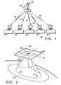
- FIG. 1 shows a simplified block diagram of a satellite communication system within which the method and apparatus of the invention can be practiced.
- FIG. 1 illustrates a single satellite 110 with digital beamformers in a typical spectrum-sharing scenario. As illustrated, there are several communication paths between satellite 110 and terrestrial-based communication devices 120, 130, and 140.
- a first beam 125 can be used to establish a link between satellite 110 and terrestrial-based communication device 120.
- a second beam 135 can be used to establish a link between satellite 110 and terrestrial-based communication device 130.
- a third beam 145 can be used to establish a link between satellite 110 and terrestrial-based communication device 140.
- DOA estimates are determined at satellite 110 for first beam 125, second beam 135, and third beam 145.
- a number of communications satellites such as illustrated by satellite 110, reside in non-geostationary orbits and are interconnected using crosslinks (not shown). In an alternate embodiment, the communications satellites are not all interconnected. For example, some communication satellites may be in geostationary orbits.
- DOA estimation algorithms can also be used to produce combinations of narrow and wide nulls or, more generally, nulls having desired widths. This flexibility also allows concurrent beams with different beamwidths and different null widths.
- the satellite In a receive mode, the satellite, at a particular point in time, desirably points a receive beam at a particular terrestrial-based communication device while preferably providing nulls in the antenna's receive pattern in the direction of any interfering signal transmitters. Accordingly, any interference received on an undesired signal path is significantly reduced.
- interfering signal transmitters can be other users in this communication system, signal sources in other systems, or jamming signals.
- at least one null in the receive antenna pattern of a satellite is directed toward and tracks each undesired signal, which is transmitted within the field of view of that satellite.
- the field of view can be defined by a current operational field of view or by the entire field of view of the satellite.
- a digital beamformer when employed in terrestrial-based communication devices 120, 130, and 140, desirably adjusts its transmit and receive antenna beam characteristics to point at least one beam at the desired satellite while directing at least one null in the direction of an interfering (undesired) signal.
- an interfering signal can be associated with another satellite in this communications system or in another system.
- the accuracy of the DOA estimates is controlled for the most part by the DOA estimation algorithm and its implementation.
- the accuracy required is governed by the angular separation between desired users, the angular separation between interference sites, and the angular separation between desired users and interference sites.
- FIG. 2 illustrates a perspective drawing of a planar array of antenna elements and an incident signal from a generalized point source.
- a three-dimensional coordinate system is illustrated having an x-axis, a y-axis, and a z-axis.
- Planar array 200 comprises a number of elements with mutual separation d x and d y in the x and y directions, respectively.
- a receive mode a first set of elements is used
- a second set of elements is used.
- the center of the coordinate system is positioned at the array's geometrical center.
- At least one signal path 215 exists between point source 210 and planar array 200.
- signal path 215 has elevation and azimuth angles ( ⁇ j and ⁇ j ) associated with it.
- Directions of arrival can be determined relative to planar array 200 or to point source 210.
- Point source 210 can represent a receiver in one case, a transmitter in a second case, or a combined receiver/transmitter in another case.
- Transceivers and transmitters can be desired signal sources and/or undesired signal sources.
- Subarray 220 comprises a first subset of the elements in planar array 200.
- Subarray 220 comprises a large number of antenna elements with individual complex weights, usually at baseband, represented by the vector w .
- Reference antenna 230 comprises a second subset of the elements in planar array 200. For simplicity of illustration, a single frequency of operation f and uniform element spacing is assumed, although these restrictions are not required for the invention.
- Reference antenna 230 has a substantially uniform gain over a desired field of view within a prescribed conical region.
- subarray 220 and the size of reference antenna 230 are controlled by software processes within certain hardware limitations, and this allows an adaptable DOA DBF subsystem.
- Field of view (FOV) 235 is the operational FOV associated with reference antenna 230.
- FOV Field of view
- the look direction can be altered to a limited extent.
- the look direction can be altered to achieve and maintain improved coverage of existing communication traffic as the satellite moves or to compensate for lost or heavy service demands of neighboring satellites in a constellation.
- Footprint 240 is associated with the FOV of reference antenna 230.
- Footprint 250 illustrates the potential coverage region for a reference beam associated with planar array 200.
- the received baseband signal from reference antenna 230 is combined with a weighted sum of the individual baseband signals from the antenna elements in subarray 220. Minimizing the composite received power by adjusting the subarray weights gives rise to a composite antenna power pattern that exhibits nulls and low-gain regions corresponding to incident directional signal activity.
- Standard digital beamforming is effective in increasing the isolation among the beams beyond that of the sidelobe structure, because beams are formed with mutual narrow nulls among them. Typically, each formed beam can exhibit a single null toward the prescribed direction of an interfering beam.
- standard digital beamforming is limited when considered with respect to its sensitivity to pointing errors, bandwidth, and orbit dynamics, particularly in the context of sticky beams.
- Sticky beams are beams which have an endpoint that remains substantially fixed on the earth's surface as the satellite moves overhead. When the assigned beam directions deviate from the actual beam directions, the sharp nulls do not coincide with the actual directions. This occurs because the assigned beam directions are no longer centered over the user locations. Consequently, standard digital beamforming provides marginal benefit.
- the limited effectiveness of the narrow nulls of standard digital beamforming is substantially eliminated by enhancing the DOA estimation algorithms to more accurately position beams and nulls. Further, wide mutual nulls add to the isolation among the formed beams even with the motion of the satellite relative to the ground sources.
- FIG. 3 shows a simplified block diagram of a direction of arrival (DOA)-aided DBF subsystem that includes a digital beamformer and direction of arrival estimator (DOAE) in accordance with a preferred embodiment of the invention.
- DOA-aided DBF subsystem 300 includes array-antenna 310, which comprises a plurality of receive (Rx) elements 312, a plurality of transmit (Tx) elements 314, a plurality of receiver/transmitter (Rx/Tx) modules 320, digital beamformer 330, DOAE 340, and controller 350.
- array-antenna 310 which comprises a plurality of receive (Rx) elements 312, a plurality of transmit (Tx) elements 314, a plurality of receiver/transmitter (Rx/Tx) modules 320, digital beamformer 330, DOAE 340, and controller 350.
- Array-antenna 310 includes elements that are preferably arranged in a linear or planar two-dimensional array; however, other array configurations are suitable. Received radio frequency (RF) signals are processed at the element level.
- RF radio frequency
- antenna elements a 1 through a K are illustrated as receiving elements 312 for incident directional signals b 1 through b J . Desirably, there are J directional signals incident on a K-element receive array.
- antenna elements a 1 ' through a k' ' are illustrated as transmitting elements 314 for transmitted directional signals b j ' through b j' '. Desirably, there are J' directional signals transmitted from a K'-element transmit array.
- At least one separate transmit (Tx) array antenna is used, and at least one receive (Rx) array antenna is used.
- Rx/Tx modules 320 comprise some separate receive functions and some separate transmit functions.
- the plurality of receiving elements 312 and the plurality of transmitting elements 314 are controlled using digital beamforming techniques.
- the antenna pattern from an array of receive elements 312 or an array of transmit elements 314 can be steered by applying linear phase weighting across the array.
- an array pattern can be shaped by the amplitude and phase weighting of the outputs of the individual receive elements 312, and another array pattern can be shaped by the amplitude and phase weighting of the inputs of the individual transmit elements 314. With wide mutual nulls, this option does not degrade the overall performance, as would be the case with narrow mutual nulls.
- Rx/Tx modules 320 are coupled to Rx elements 312 and Tx elements 314. Preferably, at least one antenna element is coupled to a Rx/Tx module.
- Rx/Tx modules 320 When operating in the receive mode, Rx/Tx modules 320 perform, among other things, the Rx functions of frequency down-conversion, filtering, amplification, and A/D conversion.
- Rx/Tx modules 320 In response to received signals, Rx/Tx modules 320 generate digital data using in-phase (I) and quadrature (Q) A/D converters. I and Q digital data respectively represent real and imaginary parts of a complex analog signal envelope and are processed by DBF 330. Desirably, Rx/Tx modules provide K digital received signals (r 1 through r K ) to DBF 330.
- Rx/Tx modules 320 when operating in the transmit mode, Rx/Tx modules 320 desirably perform, among other things, the Tx functions of frequency up-conversion, filtering, amplification, and D/A conversion. D/A converters convert digital data into corresponding analog signals for each Tx array element. Rx/Tx modules 320 generate signals suitable for transmission by Tx array elements from digital data received from DBF 330. Desirably, Rx/Tx modules are provided K' digital transmit signals (r 1 ' through r K' ') by DBF 330.
- Digital beamformer 330 is coupled to Rx/Tx modules 320. Digital data is exchanged between DBF 330 and Rx/Tx modules 320. DBF 330 implements beam forming and beam steering functions necessary to form antenna beam patterns with the desired characteristics. DBF 330 forms receive and transmit beams for the reception and transmission of directional signals with minimal inter-beam interference.
- DBF 330 is coupled via 335 to controller 350.
- Digital data is exchanged between DBF 330 and controller 350.
- Digital data includes data for operating in the receive mode and the transmit mode as well as other data for control.
- DBF 330 provides the received beam port signals ( through ) to controller 350. These signals are optimal estimates of the incident signals (b 1 through b,).
- DBF 330 obtains the transmit beam port signals (b', through b' j .) from controller 350.
- the actual transmitted signals ( through ) are optimal representations of the original versions (b', through b',).
- One of the functions of the digital beamformer is to derive T and T' transformation matrices which, operating on received and transmitted signals, respectively, produce optimal estimates of incident and actually transmitted signals.
- DBF 330 uses a best linear unbiased estimator (BLUE). This algorithm adjusts the weight coefficients of the array to achieve a minimum-variance signal estimate.
- BLUE linear unbiased estimator
- the BLUE algorithm forces deep nulls in the direction of interfering signals for each beam, and therefore, it is susceptible to pointing errors.
- Accurate DOA estimation techniques are used with the BLUE algorithm to increase its effectiveness.
- variable width nulls enhance the inter-beam isolation providing further robustness against noise and motion.
- DOAE 340 is coupled 345 to DBF 330 and is coupled 355 to controller 350. Digital data is exchanged between DOAE 340, DBF 330, and controller 350.
- DOAE 340 obtains antenna configuration data from controller 350.
- controller 350 can provide initial values for directions of arrival, calculated values for directions of arrival, and stored values of directions of arrival.
- DOAE 340 provides, among other things, reference antenna weights, and subarray weights to DBF 330.
- DOAE 340 uses knowledge of existing beams to enhance its search strategy for new directional incident signal activity. Desirably, DOAE 340 obtains existing beam information from DBF 330 and controller 350. Also, DOAE 340 uses, among other things, beam width and null width information to determine its beam assignment strategy.
- DOAE 340 is used to compute, among other things, covariance matrices, and cross-correlation vectors as discussed below.
- DOAE 340 employs a relaxation algorithm that is numerically stable and does not impose a requirement that the underlying covariance matrix have an inverse.
- DOAE 340 comprises one or more parallel processors.
- DOAE 340 stores data that serve as its instructions and that, when executed, cause DOAE 340 to carry out procedures that are discussed below.
- DOAE 340 can be implemented using digital signal processors.
- DOAE 340 can be implemented using special processors, which can include logarithm converters, inverse logarithm converters, and parallel processors.
- the processors used in DBF 330, DOAE 340, and controller 350, can use logarithmic number system (LNS) arithmetic.
- LNS-based arithmetic provides an advantage because multiplication operations can be accomplished with adders instead of multipliers.
- a LNS-based processor can include log converters, summing circuits, weighting circuits, and inverse-log converters 1.
- DBF 330 and DOAE 340 can share computational resources.
- DOAE 340 uses an N-element receive subarray to determine the distribution of directions of arrival over a desired field of view.
- N is a positive integer that is less than the total number of elements in the receive antenna array. Because a robust relaxation algorithm is employed, DOAE 340 is not restricted to use an N-dimensional subarray but can actually employ the full array to achieve a finer definition of the directional distribution of incident signal power.
- DOAE 340 receives sampled signals s 0 , s 1 ,... s N , where s 0 is the reference port signal, and s ([s 1 ,... s N ] T ) is the N-component subarray signal vector.
- the reference port signal samples are combined with a weighted sum of the N subarray port signal samples to form the composite signal samples S w + s 0 , where w is an N-dimensional complex weight vector.
- Eigenspace techniques including Singular Value Decomposition (SVD), Pseudoinverse, and Batch Covariance Relation (BCR) are numerically stable and robust alternatives for determining an optimal estimate of w . Consequently, these techniques are more suitable for solving ill-conditioned systems and more appropriate for use in the DOAE.
- the BCR approach is used.
- the advantage of the BCR technique is that it is numerically stable, even with limited arithmetic resolution, and the BCR technique can be applied iteratively to improve a current estimate for w , thereby allowing incremental refinements in a varying environment.
- the reciprocal normalized composite power pattern exhibits an incident signal directional profile in the form of peaks and high regions relative to the reference antenna power pattern, as a function of the direction angles ⁇ , and ⁇ .
- P( ⁇ , ⁇ ) is an estimate of incident directional power referenced to unity.
- Knowledge of the normalized combined power pattern allows peak-finding techniques to be applied to identify the directions of incident signal activity within the field of view of a DOA estimation subsystem. Then, using knowledge of achievable beamwidths for DBF beams, it is possible to specify beam directions that provide optimal coverage, in some practical sense. Furthermore, with the knowledge of the current beam directions, the DOA estimation subsystem needs to only search for new beam directions and this technique eliminates unnecessary computations.
- the computational complexity involved with this search technique depends on a number of factors including the step sizes used for ⁇ and ⁇ . For example, the complexity is also dependent on the accuracy required for the directions of arrival and the size of the search range in the desired FOV.
- incident signal energy having certain spectral characteristics can be used to determine where to induce nulls into the composite power pattern or a peak directional power estimate.
- incident signal energy having certain spectral characteristics can be used to determine where to induce nulls into the composite power pattern or a peak directional power estimate.
- incident signal is identified as an undesired signal (interference)
- its DOA information is important to a DBF system.
- the DBF system utilizes this knowledge to place a null at this point in each of the beams the DBF system forms.
- a DBF system can form a beam in this direction in an attempt to further identify the undesired interference. By intelligently positioning nulls, undesired signals or jamming signals are suppressed using the DOA information.
- digital beamforming refers to the creation of multiple, simultaneous, independently controlled beams at baseband, which are controlled through digital signal processing.
- a DOA-aided DBF subsystem with an enhanced DOA estimation capability, allows a communication system to employ a resource allocation policy that assigns beams to sources and nulls to interferers to optimize total capacity and quality of service.
- antenna patterns can be established to have beam and null positions that vary according to traffic density.
- DOA-aided DBF subsystem 300 shown in FIG. 3 has advantages over conventional systems with fixed beam antennas because it, among other things, adaptively adjusts antenna patterns and produces accurately positioned beams and nulls in response to received data. Desirably, the received data is used to accurately estimate the DOA for desired and undesired incident signals. In other words, DOA-aided DBF subsystem 300 provides accurate antenna beam pointing in response to demand for communication services, and it provides improved null positioning to lessen the impact of unwanted RF signals. These features are implemented through appropriate software embedded in DBF 330, DOAE 340, and controller 350.
- the DOA information must be updated as the satellites and users move relative to each other.
- the DOA is estimated for signals incident to at least one antenna array on a satellite.
- This information can be used, for example, to improve the allocation of resources by placing beams on active and high-traffic areas and by not placing beams on inactive regions. This improvement in resource allocation can enhance overall performance and reduce on-board power consumption.
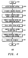
- FIG. 4 illustrates a flow diagram of a procedure for determining directions of arrival in a DOA-aided DBF subsystem in accordance with a preferred embodiment of the invention.
- Procedure 400 starts in step 402.
- a reference antenna is defined.
- the reference antenna forms a reference beam that covers a desired field of view while rejecting the remaining space with a sufficiently low sidelobe structure.
- the elements that are used to define the reference antenna are not hardware dependent.
- the reference antenna is dynamically controlled by the DOAE.
- the reference antenna varies as the size of the field of view changes and as the direction for the field of view changes. For example, in a non-geostationary satellite system fields of view change as the satellites move with respect to the surface of the earth. In addition, fields of view can be changed when beams are moved from light traffic areas to heavy traffic areas.
- an N-element subarray is selected.
- the N-element array is a subarray in the receive antenna array. In other embodiments, the N-element array is the entire receive array. Desirably, N changes as requirements change.
- the invention uses a weighted subarray in combination with a reference antenna to determine the distribution of directions of arrival over a desired field of view.
- the relaxation algorithm employed is numerically stable and robust imposing no requirement that the underlying covariance matrix have an inverse. Consequently, the system is not restricted to use a small subarray but can actually employ the full array to achieve a finer definition of the directional distribution of incident power.
- the field of view can be changed to some extent when DOA estimates are required for a specific area.
- step 410 the covariance matrix is computed.
- a cross-correlation vector is computed.
- a composite antenna pattern is computed using the previously obtained value for w .
- the composite antenna pattern, E c ( ⁇ , ⁇ ) is computed.
- step 416 the reciprocal normalized composite power pattern P ( ⁇ , ⁇ ) is computed for a plurality of points ( ⁇ , ⁇ ) within a desired field of view.
- the DOA estimates are derived for the plurality of incident signals from the reciprocal normalized composite power pattern P ( ⁇ , ⁇ ) computed at the plurality of points ( ⁇ , ⁇ ) .
- peak finding techniques are used to locate the peaks of P ( ⁇ , ⁇ ) in ( ⁇ , ⁇ ) space corresponding to the DOA estimates.
- procedure 400 ends.
- Procedure 400 is used to calculate a composite power pattern for a plurality of points within a desired field of view, and to derive DOA estimates for at least one incident signal by applying at least one peak-finding technique to the composite power pattern.
- the DOA-aided DBF subsystem establishes a beam in a direction substantially equal to the DOA estimate, when said incident signal is a desired signal; and the DOA-aided DBF subsystem directs a null in a direction substantially equal to the DOA estimate, when the incident signal is from an undesired source.
- FIG. 5 shows a graph that illustrates the directional signal activity estimated by the DOA algorithm.
- a DOA-aided DBF subsystem includes both beam steering and null steering, the computing load increases and becomes more complex. Suitable techniques are used to accomplish this. For example, using the BLUE DBF algorithm in combination with DOA estimation techniques provides a good tradeoff between performance and complexity. This combination allows the simultaneous steering of beams in the directions of the desired users and the steering of nulls in the direction of interfering signals.
- Computational complexity is also managed by controlling when calculations are performed.
- the DOA estimation calculations are performed as required.
- the update rate is dependent on a number of factors including, among other things, changes in satellite position relative to the desired and undesired transmitters and receivers. If the rate of change of the elevation angle is 0.0569°/ sec, then this corresponds to 0.005°/frame, assuming a frame length of 90 msec.
- DOA information needs to be updated every 100th frame. This can be done using appropriate digital signal processors.
- DOA-aided DBF the computational complexity can be reduced by making iterative updates to the DOA estimates.
- the BCR technique allows iterative w updates to be made, thereby providing an essentially continuous refinement of DOA estimates.
- DOA computations can be distributed and time-shared with DBF computations. Desirably, these options allow the economic use of available computational resources.
- peak detection can be made more computationally efficient by using iterative updating and searching near previously identified peaks.
- the computational complexity can also be reduced by using approximate estimates of the DOA for at least some of the incident signals.
- approximate estimates for directions of arrival are obtained for users during an acquisition phase. For example, wider FOVs and wider beams can be used during the acquisition phase.
- DOA estimation techniques can be formulated for a single frequency of operation, presumably the center frequency of a communication system's operational bandwidth.
- the bandwidth B is a small fraction of the carrier frequency f c
- DOA estimation techniques at f c , yielding very little performance degradation at the band edges.
- the fractional bandwidth B / f c increases, the degradation manifests itself in increased estimation errors.
- DOA estimates may be derived for individual subbands in a time-shared fashion.
- a GPS-aided location system can also be used to obtain the directions of arrival.
- location system data can be used to provide limits and initial conditions for BCR.
- DOA estimation algorithms could be used to identify unknown sources of interference.
- coarse location data can be provided to terrestrial based devices by satellites in a communications system.
- the method and apparatus of the present invention enable the capabilities of a satellite communication system to be greatly enhanced by using antenna patterns with accurately positioned beams and nulls. Using accurately positioned nulls to minimize the effect of interfering signals can be optimized for various missions, and additional cost benefits can be accrued by the system using the method and apparatus of the invention. Furthermore, using the method and apparatus of the present invention with wide nulls adds to the overall system robustness.
Landscapes
- Physics & Mathematics (AREA)
- Engineering & Computer Science (AREA)
- General Physics & Mathematics (AREA)
- Radar, Positioning & Navigation (AREA)
- Remote Sensing (AREA)
- Variable-Direction Aerials And Aerial Arrays (AREA)
- Radio Transmission System (AREA)
Applications Claiming Priority (3)
| Application Number | Priority Date | Filing Date | Title |
|---|---|---|---|
| US09/305,347 US6075484A (en) | 1999-05-03 | 1999-05-03 | Method and apparatus for robust estimation of directions of arrival for antenna arrays |
| US305347 | 1999-05-03 | ||
| PCT/US2000/007472 WO2000067042A1 (en) | 1999-05-03 | 2000-03-21 | Robust estimation of doa for antenna arrays |
Publications (2)
| Publication Number | Publication Date |
|---|---|
| EP1177456A1 EP1177456A1 (en) | 2002-02-06 |
| EP1177456B1 true EP1177456B1 (en) | 2005-06-08 |
Family
ID=23180428
Family Applications (1)
| Application Number | Title | Priority Date | Filing Date |
|---|---|---|---|
| EP00919499A Expired - Lifetime EP1177456B1 (en) | 1999-05-03 | 2000-03-21 | Robust estimation of doa for antenna arrays |
Country Status (6)
| Country | Link |
|---|---|
| US (1) | US6075484A (enExample) |
| EP (1) | EP1177456B1 (enExample) |
| JP (1) | JP2002543436A (enExample) |
| AU (1) | AU4017800A (enExample) |
| DE (1) | DE60020693T2 (enExample) |
| WO (1) | WO2000067042A1 (enExample) |
Cited By (2)
| Publication number | Priority date | Publication date | Assignee | Title |
|---|---|---|---|---|
| CN104298850A (zh) * | 2014-07-18 | 2015-01-21 | 哈尔滨工业大学深圳研究生院 | 信源数未知的相干信号测向方法及系统 |
| US20240272261A1 (en) * | 2021-08-31 | 2024-08-15 | Saab Ab | Multi-channel active array system and method for obtaining positional information of an object |
Families Citing this family (74)
| Publication number | Priority date | Publication date | Assignee | Title |
|---|---|---|---|---|
| SE509776C2 (sv) * | 1997-07-04 | 1999-03-08 | Ericsson Telefon Ab L M | Anordning och förfarande vid antennlobsstyrning i radiokommunikationssystem |
| GB2337171A (en) * | 1998-05-06 | 1999-11-10 | Motorola Ltd | Direction finder |
| JP3662772B2 (ja) * | 1999-05-24 | 2005-06-22 | 東芝テック株式会社 | 無線通信システム |
| CN1107424C (zh) * | 2000-06-12 | 2003-04-30 | 信息产业部电信科学技术研究院 | 在频分双工无线通信系统中使用智能天线的方法与装置 |
| US7245880B1 (en) * | 2000-08-31 | 2007-07-17 | Intel Corporation | Transmit power control within a wireless transmitter |
| JP2002084217A (ja) * | 2000-09-08 | 2002-03-22 | Matsushita Electric Ind Co Ltd | 基地局装置および到来方向推定方法 |
| US6606055B2 (en) * | 2000-12-06 | 2003-08-12 | Harris Corporation | Phased array communication system providing airborne crosslink and satellite communication receive capability |
| ATE289451T1 (de) * | 2000-12-29 | 2005-03-15 | Nokia Corp | Basisstation, basisstationsmodul und verfahren zum schätzen von parametern für die aufwärtssignale |
| JP4569015B2 (ja) * | 2001-02-28 | 2010-10-27 | ソニー株式会社 | 広帯域アレイアンテナ |
| JP3767799B2 (ja) * | 2001-04-09 | 2006-04-19 | 日本電気株式会社 | アレーアンテナのヌル方向制御方法及び装置 |
| EP1253434B1 (en) * | 2001-04-27 | 2010-04-07 | Mitsubishi Electric R&D Centre Europe B.V. | Method for estimating a direction of arrival |
| US7327798B2 (en) | 2001-10-19 | 2008-02-05 | Lg Electronics Inc. | Method and apparatus for transmitting/receiving signals in multiple-input multiple-output communication system provided with plurality of antenna elements |
| KR100463526B1 (ko) * | 2002-01-04 | 2004-12-29 | 엘지전자 주식회사 | 다중 입력 다중 출력 시스템에서의 전력 할당 방법 |
| US6738018B2 (en) * | 2002-05-01 | 2004-05-18 | Harris Corporation | All digital phased array using space/time cascaded processing |
| US7084801B2 (en) * | 2002-06-05 | 2006-08-01 | Siemens Corporate Research, Inc. | Apparatus and method for estimating the direction of arrival of a source signal using a microphone array |
| US7151951B2 (en) * | 2002-12-23 | 2006-12-19 | Telefonktiebolaget Lm Ericsson (Publ) | Using beamforming and closed loop transmit diversity in a multi-beam antenna system |
| US7277730B2 (en) | 2002-12-26 | 2007-10-02 | Nokia Corporation | Method of allocating radio resources in telecommunication system, and telecommunication system |
| KR100770875B1 (ko) | 2004-05-24 | 2007-10-26 | 삼성전자주식회사 | 배열 안테나 시스템에서 간섭전력 추정을 이용한 빔 형성장치 및 방법 |
| US7382743B1 (en) * | 2004-08-06 | 2008-06-03 | Lockheed Martin Corporation | Multiple-beam antenna system using hybrid frequency-reuse scheme |
| US6992622B1 (en) | 2004-10-15 | 2006-01-31 | Interdigital Technology Corporation | Wireless communication method and antenna system for determining direction of arrival information to form a three-dimensional beam used by a transceiver |
| US8164533B1 (en) | 2004-10-29 | 2012-04-24 | Lockhead Martin Corporation | Horn antenna and system for transmitting and/or receiving radio frequency signals in multiple frequency bands |
| JP2006258529A (ja) * | 2005-03-16 | 2006-09-28 | Fujitsu Ten Ltd | 電波到来方向推定装置及び方法 |
| US7239270B2 (en) * | 2005-05-31 | 2007-07-03 | Research In Motion Limited | Mobile wireless communications device comprising a satellite positioning system antenna and electrically conductive director element therefor |
| US7436370B2 (en) * | 2005-10-14 | 2008-10-14 | L-3 Communications Titan Corporation | Device and method for polarization control for a phased array antenna |
| KR100749451B1 (ko) * | 2005-12-02 | 2007-08-14 | 한국전자통신연구원 | Ofdm 기지국 시스템에서의 스마트 안테나 빔 형성 방법및 장치 |
| US7414578B1 (en) * | 2006-09-27 | 2008-08-19 | Rockwell Collins, Inc. | Method for efficiently computing the beamforming weights for a large antenna array |
| US9354633B1 (en) | 2008-10-31 | 2016-05-31 | Rockwell Collins, Inc. | System and method for ground navigation |
| US9939526B2 (en) | 2007-09-06 | 2018-04-10 | Rockwell Collins, Inc. | Display system and method using weather radar sensing |
| US9733349B1 (en) | 2007-09-06 | 2017-08-15 | Rockwell Collins, Inc. | System for and method of radar data processing for low visibility landing applications |
| FR2931302B1 (fr) * | 2008-05-16 | 2010-07-30 | Centre Nat Etd Spatiales | Systeme antennaire multi-faisceaux pour couverture multispots et satellite comprenant un tel systeme |
| US7737904B2 (en) * | 2008-06-11 | 2010-06-15 | Lockheed Martin Corporation | Antenna systems for multiple frequency bands |
| US8558731B1 (en) * | 2008-07-02 | 2013-10-15 | Rockwell Collins, Inc. | System for and method of sequential lobing using less than full aperture antenna techniques |
| US8077078B1 (en) | 2008-07-25 | 2011-12-13 | Rockwell Collins, Inc. | System and method for aircraft altitude measurement using radar and known runway position |
| JP4954332B2 (ja) * | 2008-10-30 | 2012-06-13 | 三菱電機株式会社 | 通信装置および通信システム |
| US20100123618A1 (en) * | 2008-11-19 | 2010-05-20 | Harris Corporation | Closed loop phase control between distant points |
| US7969358B2 (en) * | 2008-11-19 | 2011-06-28 | Harris Corporation | Compensation of beamforming errors in a communications system having widely spaced antenna elements |
| US7855681B2 (en) * | 2008-11-19 | 2010-12-21 | Harris Corporation | Systems and methods for determining element phase center locations for an array of antenna elements |
| US20100124263A1 (en) * | 2008-11-19 | 2010-05-20 | Harris Corporation | Systems for determining a reference signal at any location along a transmission media |
| US8170088B2 (en) * | 2008-11-19 | 2012-05-01 | Harris Corporation | Methods for determining a reference signal at any location along a transmission media |
| US20100125347A1 (en) * | 2008-11-19 | 2010-05-20 | Harris Corporation | Model-based system calibration for control systems |
| US7970365B2 (en) * | 2008-11-19 | 2011-06-28 | Harris Corporation | Systems and methods for compensating for transmission phasing errors in a communications system using a receive signal |
| US8804612B1 (en) * | 2009-02-06 | 2014-08-12 | Qualcomm Incorporated | Triggering and transmitting sounding packets for wireless communications |
| KR101097843B1 (ko) | 2010-12-08 | 2011-12-23 | 엘아이지넥스원 주식회사 | 위상각 검출 장치 및 그 방법 |
| US9019145B1 (en) | 2011-07-14 | 2015-04-28 | Rockwell Collins, Inc. | Ground clutter rejection for weather radar |
| CN102385048A (zh) * | 2011-08-10 | 2012-03-21 | 西安交通大学 | 基于均匀线阵的混合信号方向估计方法 |
| US8947294B1 (en) * | 2011-11-02 | 2015-02-03 | Lockheed Martin Corporation | Method and system for adaptively cancelling clutter from the sidelobes of a ground-based radar |
| EP2669708B1 (en) * | 2012-06-01 | 2016-09-07 | Airbus DS GmbH | Method of detecting a direction of arrival of at least one interference signal and system to carry out said method |
| US9262932B1 (en) | 2013-04-05 | 2016-02-16 | Rockwell Collins, Inc. | Extended runway centerline systems and methods |
| JP2015012568A (ja) * | 2013-07-02 | 2015-01-19 | 三星電子株式会社Samsung Electronics Co.,Ltd. | 指向性制御装置、および指向性制御方法 |
| KR102177553B1 (ko) * | 2014-03-27 | 2020-11-11 | 삼성전자주식회사 | 다중 사용자 지원을 위한 빔포밍 방법 및 장치 |
| US10270524B2 (en) | 2014-04-15 | 2019-04-23 | Space Systems/Loral, Llc | Broadband satellite payload architecture |
| CN104181529A (zh) * | 2014-07-21 | 2014-12-03 | 中国科学院电子学研究所 | 一种Ka波段合成孔径雷达SAR信号处理方法和设备 |
| US10928510B1 (en) | 2014-09-10 | 2021-02-23 | Rockwell Collins, Inc. | System for and method of image processing for low visibility landing applications |
| US20160301463A1 (en) * | 2015-04-10 | 2016-10-13 | Space Systems/Loral, Llc | Broadband satellite payload architecture |
| WO2016174774A1 (ja) * | 2015-04-30 | 2016-11-03 | 三菱電機株式会社 | 送信局、制御局、受信局、データ伝送システムおよびデータ伝送方法 |
| US10705201B1 (en) | 2015-08-31 | 2020-07-07 | Rockwell Collins, Inc. | Radar beam sharpening system and method |
| US10700762B2 (en) * | 2016-05-04 | 2020-06-30 | Telefonaktiebolaget Lm Ericsson (Publ) | Beam forming using an antenna arrangement |
| US10228460B1 (en) | 2016-05-26 | 2019-03-12 | Rockwell Collins, Inc. | Weather radar enabled low visibility operation system and method |
| US10353068B1 (en) | 2016-07-28 | 2019-07-16 | Rockwell Collins, Inc. | Weather radar enabled offshore operation system and method |
| US10288715B2 (en) * | 2016-09-09 | 2019-05-14 | Raytheon Company | Systems and methods for direction finding using augmented spatial sample covariance matrices |
| CN106788648B (zh) * | 2016-11-30 | 2020-04-24 | 西南交通大学 | 一种智能天线系统的自适应波束形成方法 |
| EP3616332A1 (en) | 2017-04-28 | 2020-03-04 | Fraunhofer Gesellschaft zur Förderung der Angewand | Specular component estimation in a wireless communication network |
| JP6926702B2 (ja) * | 2017-06-09 | 2021-08-25 | 富士通株式会社 | 無線通信装置及びビーム制御方法 |
| CN110426670B (zh) * | 2018-12-26 | 2022-09-23 | 西安电子科技大学 | 基于tls-cs的外辐射源雷达超分辨doa估计方法 |
| CN110380770B (zh) * | 2019-06-10 | 2021-07-06 | 浙江大学 | 一种低轨移动卫星通信网络的自适应对星方法 |
| US11316268B2 (en) * | 2019-06-24 | 2022-04-26 | Rockwell Collins, Inc. | Method for antenna beam and null steering under high platform dynamics |
| KR102812754B1 (ko) | 2019-10-15 | 2025-05-23 | 삼성전자주식회사 | 통신 장치 및 통신 장치의 데이터 수신 방법 |
| WO2022011510A1 (zh) * | 2020-07-13 | 2022-01-20 | 北京小米移动软件有限公司 | 一种通信方法、通信装置及存储介质 |
| KR102499336B1 (ko) * | 2021-07-08 | 2023-02-14 | 국방과학연구소 | 적응형 널 폭 제어 장치와 방법 및 이를 이용한 기지국 |
| US11929798B2 (en) * | 2021-08-30 | 2024-03-12 | Rockwell Collins, Inc. | Technique for post-correlation beamforming |
| US20230106766A1 (en) * | 2021-10-05 | 2023-04-06 | Qualcomm Incorporated | Nulling for inter-user equipment interference cancellation |
| KR102516903B1 (ko) * | 2021-11-11 | 2023-04-03 | 한국전자통신연구원 | 통신 시스템에서 다수의 신호원들의 동시 전력 추정을 위한 방법 및 장치 |
| US20240393427A1 (en) * | 2023-05-23 | 2024-11-28 | Rockwell Collins, Inc. | Aesa-based synthetic nulling for enhanced radar ground clutter suppression |
| CN119619985A (zh) * | 2024-12-03 | 2025-03-14 | 中国空间技术研究院 | 通信卫星干扰源定位方法及系统 |
Family Cites Families (5)
| Publication number | Priority date | Publication date | Assignee | Title |
|---|---|---|---|---|
| US4353119A (en) * | 1980-06-13 | 1982-10-05 | Motorola Inc. | Adaptive antenna array including batch covariance relaxation apparatus and method |
| US4771289A (en) * | 1982-05-28 | 1988-09-13 | Hazeltine Corporation | Beamforming/null-steering adaptive array |
| US4720712A (en) * | 1985-08-12 | 1988-01-19 | Raytheon Company | Adaptive beam forming apparatus |
| US5144322A (en) * | 1988-11-25 | 1992-09-01 | The United States Of America As Represented By The Secretary Of The Navy | Large-aperture sparse array detector system for multiple emitter location |
| US5754138A (en) * | 1996-10-30 | 1998-05-19 | Motorola, Inc. | Method and intelligent digital beam forming system for interference mitigation |
-
1999
- 1999-05-03 US US09/305,347 patent/US6075484A/en not_active Expired - Lifetime
-
2000
- 2000-03-21 JP JP2000615827A patent/JP2002543436A/ja not_active Ceased
- 2000-03-21 WO PCT/US2000/007472 patent/WO2000067042A1/en not_active Ceased
- 2000-03-21 AU AU40178/00A patent/AU4017800A/en not_active Abandoned
- 2000-03-21 EP EP00919499A patent/EP1177456B1/en not_active Expired - Lifetime
- 2000-03-21 DE DE60020693T patent/DE60020693T2/de not_active Expired - Lifetime
Cited By (3)
| Publication number | Priority date | Publication date | Assignee | Title |
|---|---|---|---|---|
| CN104298850A (zh) * | 2014-07-18 | 2015-01-21 | 哈尔滨工业大学深圳研究生院 | 信源数未知的相干信号测向方法及系统 |
| US20240272261A1 (en) * | 2021-08-31 | 2024-08-15 | Saab Ab | Multi-channel active array system and method for obtaining positional information of an object |
| US12099130B2 (en) * | 2021-08-31 | 2024-09-24 | Saab Ab | Multi-channel active array system and method for obtaining positional information of an object |
Also Published As
| Publication number | Publication date |
|---|---|
| WO2000067042A1 (en) | 2000-11-09 |
| AU4017800A (en) | 2000-11-17 |
| DE60020693T2 (de) | 2005-10-20 |
| US6075484A (en) | 2000-06-13 |
| DE60020693D1 (de) | 2005-07-14 |
| JP2002543436A (ja) | 2002-12-17 |
| EP1177456A1 (en) | 2002-02-06 |
Similar Documents
| Publication | Publication Date | Title |
|---|---|---|
| EP1177456B1 (en) | Robust estimation of doa for antenna arrays | |
| EP0956612B1 (en) | Antenna beam patterns having wide nulls | |
| US6697633B1 (en) | Method permitting increased frequency re-use in a communication network, by recovery of transmitted information from multiple cochannel signals | |
| US6392596B1 (en) | Single-port weighting systems for GPS reception in multiple-interference environments | |
| US6215983B1 (en) | Method and apparatus for complex phase equalization for use in a communication system | |
| US6208295B1 (en) | Method for processing radio signals that are subject to unwanted change during propagation | |
| US20100190507A1 (en) | Communications systems including adaptive antenna systems and methods for inter-system and intra-system interference reduction | |
| US6535666B1 (en) | Method and apparatus for separating signals transmitted over a waveguide | |
| US6310704B1 (en) | Communication apparatus for transmitting and receiving signals over a fiber-optic waveguide using different frequency bands of light | |
| US6658234B1 (en) | Method for extending the effective dynamic range of a radio receiver system | |
| CA2272930C (en) | Cochannel signal processing system | |
| CN115396005B (zh) | 多波束卫星的波束间干扰及用户信道向量确定方法及装置 | |
| Balamurugan et al. | DOA tracking for seamless connectivity in beamformed IoT-based drones | |
| US6930637B2 (en) | Method and apparatus for high resolution tracking via mono-pulse beam-forming in a communication system | |
| Huang et al. | Frequency-domain AoA estimation and beamforming with wideband hybrid arrays | |
| US7068219B2 (en) | Communications system including phased array antenna providing nulling and related methods | |
| US5977907A (en) | Method and system for antenna pattern synthesis based on geographical distribution of subscribers | |
| US7414578B1 (en) | Method for efficiently computing the beamforming weights for a large antenna array | |
| EP1894320B1 (en) | Communications systems including adaptive antenna systems and methods for inter-system and intra-system interference reduction | |
| AU727787B2 (en) | Cochannel signal processing system | |
| Alio et al. | Adaptive array antennas for mobile earth stations: A review | |
| AU763322B2 (en) | A method for increasing the capacity of a two-way communication system by permitting cochannel signals | |
| AU6654200A (en) | Cochannel signal processing system | |
| Senapati | A thesis submitted To | |
| Pratt | Multiple Antenna GPS-A Technology Ripe for Development |
Legal Events
| Date | Code | Title | Description |
|---|---|---|---|
| PUAI | Public reference made under article 153(3) epc to a published international application that has entered the european phase |
Free format text: ORIGINAL CODE: 0009012 |
|
| 17P | Request for examination filed |
Effective date: 20011203 |
|
| AK | Designated contracting states |
Kind code of ref document: A1 Designated state(s): AT BE CH CY DE DK ES FI FR GB GR IE IT LI LU MC NL PT SE |
|
| 17Q | First examination report despatched |
Effective date: 20040223 |
|
| RBV | Designated contracting states (corrected) |
Designated state(s): DE FI FR GB SE |
|
| GRAP | Despatch of communication of intention to grant a patent |
Free format text: ORIGINAL CODE: EPIDOSNIGR1 |
|
| GRAS | Grant fee paid |
Free format text: ORIGINAL CODE: EPIDOSNIGR3 |
|
| GRAA | (expected) grant |
Free format text: ORIGINAL CODE: 0009210 |
|
| AK | Designated contracting states |
Kind code of ref document: B1 Designated state(s): DE FI FR GB SE |
|
| REG | Reference to a national code |
Ref country code: GB Ref legal event code: FG4D |
|
| REG | Reference to a national code |
Ref country code: SE Ref legal event code: TRGR |
|
| REF | Corresponds to: |
Ref document number: 60020693 Country of ref document: DE Date of ref document: 20050714 Kind code of ref document: P |
|
| ET | Fr: translation filed | ||
| PLBE | No opposition filed within time limit |
Free format text: ORIGINAL CODE: 0009261 |
|
| STAA | Information on the status of an ep patent application or granted ep patent |
Free format text: STATUS: NO OPPOSITION FILED WITHIN TIME LIMIT |
|
| 26N | No opposition filed |
Effective date: 20060309 |
|
| REG | Reference to a national code |
Ref country code: GB Ref legal event code: 732E Free format text: REGISTERED BETWEEN 20110127 AND 20110202 |
|
| REG | Reference to a national code |
Ref country code: DE Ref legal event code: R081 Ref document number: 60020693 Country of ref document: DE Owner name: MOTOROLA MOBILITY, INC. ( N.D. GES. D. STAATES, US Free format text: FORMER OWNER: MOTOROLA, INC., SCHAUMBURG, US Effective date: 20110324 Ref country code: DE Ref legal event code: R081 Ref document number: 60020693 Country of ref document: DE Owner name: MOTOROLA MOBILITY, INC. ( N.D. GES. D. STAATES, US Free format text: FORMER OWNER: MOTOROLA, INC., SCHAUMBURG, ILL., US Effective date: 20110324 Ref country code: DE Ref legal event code: R081 Ref document number: 60020693 Country of ref document: DE Owner name: GOOGLE TECHNOLOGY HOLDINGS LLC, MOUNTAIN VIEW, US Free format text: FORMER OWNER: MOTOROLA, INC., SCHAUMBURG, ILL., US Effective date: 20110324 |
|
| REG | Reference to a national code |
Ref country code: FR Ref legal event code: TP Owner name: MOTOROLA MOBILITY, INC., US Effective date: 20110912 |
|
| REG | Reference to a national code |
Ref country code: FR Ref legal event code: PLFP Year of fee payment: 17 |
|
| REG | Reference to a national code |
Ref country code: FR Ref legal event code: PLFP Year of fee payment: 18 |
|
| REG | Reference to a national code |
Ref country code: GB Ref legal event code: 732E Free format text: REGISTERED BETWEEN 20170831 AND 20170906 |
|
| REG | Reference to a national code |
Ref country code: FR Ref legal event code: CD Owner name: GOOGLE TECHNOLOGY HOLDINGS LLC, US Effective date: 20171214 Ref country code: FR Ref legal event code: TP Owner name: GOOGLE TECHNOLOGY HOLDINGS LLC, US Effective date: 20171214 |
|
| REG | Reference to a national code |
Ref country code: FR Ref legal event code: PLFP Year of fee payment: 19 |
|
| REG | Reference to a national code |
Ref country code: DE Ref legal event code: R082 Ref document number: 60020693 Country of ref document: DE Representative=s name: BETTEN & RESCH PATENT- UND RECHTSANWAELTE PART, DE Ref country code: DE Ref legal event code: R081 Ref document number: 60020693 Country of ref document: DE Owner name: GOOGLE TECHNOLOGY HOLDINGS LLC, MOUNTAIN VIEW, US Free format text: FORMER OWNER: MOTOROLA MOBILITY, INC. ( N.D. GES. D. STAATES DELAWARE ), LIBERTYVILLE, LLL., US |
|
| PGFP | Annual fee paid to national office [announced via postgrant information from national office to epo] |
Ref country code: DE Payment date: 20190327 Year of fee payment: 20 Ref country code: FI Payment date: 20190327 Year of fee payment: 20 Ref country code: FR Payment date: 20190325 Year of fee payment: 20 |
|
| PGFP | Annual fee paid to national office [announced via postgrant information from national office to epo] |
Ref country code: SE Payment date: 20190326 Year of fee payment: 20 |
|
| PGFP | Annual fee paid to national office [announced via postgrant information from national office to epo] |
Ref country code: GB Payment date: 20190404 Year of fee payment: 20 |
|
| REG | Reference to a national code |
Ref country code: DE Ref legal event code: R071 Ref document number: 60020693 Country of ref document: DE |
|
| REG | Reference to a national code |
Ref country code: GB Ref legal event code: PE20 Expiry date: 20200320 |
|
| PG25 | Lapsed in a contracting state [announced via postgrant information from national office to epo] |
Ref country code: GB Free format text: LAPSE BECAUSE OF EXPIRATION OF PROTECTION Effective date: 20200320 |
|
| REG | Reference to a national code |
Ref country code: SE Ref legal event code: EUG |
|
| REG | Reference to a national code |
Ref country code: FI Ref legal event code: MAE |
|
| P01 | Opt-out of the competence of the unified patent court (upc) registered |
Effective date: 20230511 |