EP1176374B1 - Akkumulator für eine nach dem Orifice-Prinzip arbeitende Klimaanlage, insbesondere Fahrzeugklimaanlage - Google Patents
Akkumulator für eine nach dem Orifice-Prinzip arbeitende Klimaanlage, insbesondere Fahrzeugklimaanlage Download PDFInfo
- Publication number
- EP1176374B1 EP1176374B1 EP01115545A EP01115545A EP1176374B1 EP 1176374 B1 EP1176374 B1 EP 1176374B1 EP 01115545 A EP01115545 A EP 01115545A EP 01115545 A EP01115545 A EP 01115545A EP 1176374 B1 EP1176374 B1 EP 1176374B1
- Authority
- EP
- European Patent Office
- Prior art keywords
- screen
- housing
- carrier
- outlet pipe
- accumulator
- Prior art date
- Legal status (The legal status is an assumption and is not a legal conclusion. Google has not performed a legal analysis and makes no representation as to the accuracy of the status listed.)
- Expired - Lifetime
Links
- 238000004378 air conditioning Methods 0.000 claims abstract description 7
- 239000003507 refrigerant Substances 0.000 claims description 18
- 239000004952 Polyamide Substances 0.000 claims description 7
- 229920002647 polyamide Polymers 0.000 claims description 7
- 239000002274 desiccant Substances 0.000 claims description 4
- 238000012216 screening Methods 0.000 claims 2
- 230000002093 peripheral effect Effects 0.000 description 10
- 125000006850 spacer group Chemical group 0.000 description 10
- 239000004033 plastic Substances 0.000 description 6
- 238000009434 installation Methods 0.000 description 4
- 239000004744 fabric Substances 0.000 description 3
- 239000007789 gas Substances 0.000 description 3
- 239000002184 metal Substances 0.000 description 3
- 238000000034 method Methods 0.000 description 3
- 239000012071 phase Substances 0.000 description 3
- 230000005484 gravity Effects 0.000 description 2
- 239000007788 liquid Substances 0.000 description 2
- 238000004519 manufacturing process Methods 0.000 description 2
- 239000002245 particle Substances 0.000 description 2
- 238000003466 welding Methods 0.000 description 2
- 206010010774 Constipation Diseases 0.000 description 1
- 230000002411 adverse Effects 0.000 description 1
- 238000005516 engineering process Methods 0.000 description 1
- 239000007792 gaseous phase Substances 0.000 description 1
- 238000005461 lubrication Methods 0.000 description 1
- 238000007665 sagging Methods 0.000 description 1
- 239000000565 sealant Substances 0.000 description 1
- 238000007789 sealing Methods 0.000 description 1
Images

Classifications
-
- F—MECHANICAL ENGINEERING; LIGHTING; HEATING; WEAPONS; BLASTING
- F25—REFRIGERATION OR COOLING; COMBINED HEATING AND REFRIGERATION SYSTEMS; HEAT PUMP SYSTEMS; MANUFACTURE OR STORAGE OF ICE; LIQUEFACTION SOLIDIFICATION OF GASES
- F25B—REFRIGERATION MACHINES, PLANTS OR SYSTEMS; COMBINED HEATING AND REFRIGERATION SYSTEMS; HEAT PUMP SYSTEMS
- F25B43/00—Arrangements for separating or purifying gases or liquids; Arrangements for vaporising the residuum of liquid refrigerant, e.g. by heat
- F25B43/006—Accumulators
-
- F—MECHANICAL ENGINEERING; LIGHTING; HEATING; WEAPONS; BLASTING
- F25—REFRIGERATION OR COOLING; COMBINED HEATING AND REFRIGERATION SYSTEMS; HEAT PUMP SYSTEMS; MANUFACTURE OR STORAGE OF ICE; LIQUEFACTION SOLIDIFICATION OF GASES
- F25B—REFRIGERATION MACHINES, PLANTS OR SYSTEMS; COMBINED HEATING AND REFRIGERATION SYSTEMS; HEAT PUMP SYSTEMS
- F25B43/00—Arrangements for separating or purifying gases or liquids; Arrangements for vaporising the residuum of liquid refrigerant, e.g. by heat
- F25B43/003—Filters
Definitions
- An accumulator known from the market comprises an am Outlet tube supported sieve holder with a cylindrical surface executed sieve. When mounting the filter holder this is pushed onto the outlet pipe from one end. In such a Siebango is the screen surface oversized, making the sieve unnecessarily big and expensive power.
- the assembly by pushing causes the Installation step for the filter holder necessary before installation the outlet pipe must be done, which is for the assembly process represents an adverse restriction. Additionally lets such a postponement hardly automate.
- the supporting webs Prevent that, if not a self-supporting Sieve fabric is used, this between marginal Seating surfaces sags and z. B. on the passage opening sets, causing the screen surface on the cross-sectional area the passage opening would be limited.
- the positioning element may be one of a receiving opening of the outlet tube tightly received positioning be, in which the passage opening formed axially is.
- Passage and “Positioning” elegantly in a component with each other connected.
- the holding device can be designed as a clip element be, which at least partially surrounds the outlet tube.
- Such a holding device is inexpensive and suitable for automatic mounting.
- the accumulator has the portafilter or the sieve to the housing bottom towards spacer webs, which are separated from each other by fürgangsnuten are spaced, wherein the through-grooves with communicate with the passageway.
- the portafilter is made of polyamide.
- Polyamide is robust and inexpensive. Seats between Leave components made of polyamide and metal components to perform tightly. This is especially true of Advantage, if in addition to a filter holder made of polyamide Outlet pipe made of metal in the embodiment in which the passage opening is guided in the positioning element is, is used. Here can on other sealants be waived.
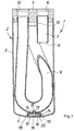
- the overall in Figure 1 provided with the reference numeral 1 Accumulator for a vehicle air conditioner has a cylindrical Housing 2 on. This one has a cylindrical Circumferential wall 3 and a slightly outwardly inverted bottom wall 4. In the installed position upwards is the accumulator 1 completed by a housing cover 5. In this is a housing inlet 6 is formed, which is the beginning of a Flow path for refrigerant through the accumulator. 1 represents. The housing inlet 6 is connected to a not shown Refrigerant inlet line connectable.
- an inlet pipe 7 To the interior of the housing 2 through the flow path downstream of the housing inlet 6 through an inlet pipe 7 continued. This is with his, the current entrance forming end portion inserted into the housing cover 5 and fixed there in a suitable manner. In the housing interior towards the inlet tube opens via an outlet opening 8. Overall, the inlet pipe 7 extends in the installed position from the housing cover 5 down over about one-third of the Longitudinal extension of the housing 2.
- the present in the interior of the housing 2 refrigerant can leave the housing 2 via an outlet pipe 9.
- the arranged in the housing 2 outlet 9 has a Entry opening 10 on. This is the housing cover. 5 adjacent, ie in the installation position in the uppermost area the L josserstrekkung of the housing 2 is arranged.
- the Outlet pipe 9 is U-shaped in the housing 2 in the manner of a siphon curved. In addition, the outlet pipe 9 is also bent perpendicular to the plane of the figure so that the inlet opening 10 is arranged behind the plane of the drawing is.
- Outlet pipe 9 In the lowest position of the wall in the installation position Outlet pipe 9 is formed a receiving opening 11, whose function will be described later.
- the outlet side is the outlet tube 9 with an end portion - Similar to the inlet pipe 7 - in the housing cover 5 inserted and fixed there.
- the outlet pipe 9 opens into a housing outlet 12, which with a not represented refrigerant return line is connectable.
- outlet tube 9 In the interior of the housing 2 is outside the outlet tube 9 still desiccant, z. In the form of a packet, arranged, not shown for clarity is.
- the receiving opening 11 of the outlet tube 9 serves to receive a positioning pin 13 of a filter holder 14 from Polyamide.
- the outer diameter of the positioning pin 13th is so on the inner diameter of the receiving opening eleventh agreed that the positioning pin 13 tight in the Receiving opening 11 is located.
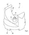
- the portafilter 14 is between the outlet tube 9 and the Bottom wall 4 of the housing 2 is arranged. He will be following with reference to Figures 2 and 3 described in more detail:
- a central through hole 15 formed part of a passageway from the interior of the outlet tube 9 through the portafilter 14 and a worn by this, not shown in the drawing Sieve, which will be discussed in more detail, to represents lower portion of the interior of the housing 2.
- the through hole widens 15 in the direction of the filter holder 14 towards a Passage space 16, which on the passage opening 15th opposite side of the wire and otherwise from the Siebyes 14 is limited.
- the passage space 16 is also part of the passageway.
- the sieve is a flat circular fabric made of metal or plastic. This lies on four supporting webs 17 of the Siebangos 14 on.
- the support webs 17 extend from the inner wall of a coaxial to the passage opening 15 Peripheral wall 18 of the portafilter 14 from in the direction of Through opening 15 inwards.
- the diameter of the sieve is larger than the diameter of the inner wall of the peripheral wall 18, so that the sieve on the support webs 17 and on the end face of the peripheral wall 18, in which the bearing surfaces the support bars 17 just expire, rests.
- the sieve is where it is at the front of the peripheral wall 18 rests, by means of an ultrasonic welding process welded.
- the effective screen area Due to the bearing surfaces on the support webs 17 and the peripheral wall 18 has the effective screen area the screen is about the shape of a cloverleaf.
- the effective Sieve surface has a multiple of the size of the cross-sectional area the passage opening 15th
- the front ends 21 are made of manufacturing technology Beveled reasons.
- a clip element 22 which is an integral part of the portafilter 14 is.
- the clip element 22 has two formed as a ring sections Klipsinatel 23.
- the accumulator 1 is assembled as follows:
- the filter holder 14 is positioned so that the positioning pin 13 in the receiving opening 11th can slide and the Klipsinatel 23 completely on Create outlet pipe 9. The filter holder 14 is then ready assembled.
- the accumulator 1 is then completely assembled. In this finished assembled state, the spacer bars 19 still a small distance to the bottom wall 4.
- the accumulator 1 works with the vehicle air conditioner together as follows:
- Oil additionally contained in the refrigerant drops due to down and its greater specific gravity Therefore, it forms a layer over the bottom wall 4.
- the gas phase of the refrigerant is through the desiccant freed from the moisture contained in it.
- the Dried gas phase of the refrigerant passes through the Inlet opening 10 in the outlet pipe 9 and flows through this towards the housing outlet 12th
- Chips which are also in the bottom area of the housing 2 are set off from the sieve, inside the outlet tube 9 to arrive or the passage opening 15 to clog.
- the support webs 17 prevent that the sieve on the Sagging surface sags.
- the oil passes through the passage opening 15 in the Outlet pipe 9 and forms there an oil level, the Level with that of the oil outside the outlet pipe 9 communicates.
- the way in the outlet pipe getting oil is from the passing gaseous Refrigerant first as an oil film on the inside of the Outlet pipe 9 also in the direction of the housing outlet 12 driven and finally absorbed. From there the dried gaseous refrigerant and the entrained Oil further into the refrigerant drain line, not shown. The oil is thus returned and gets to Input side of a compressor where it is for lubrication serves.
- this made of a mesh with an overmolded edge made of plastic Preference is given as a plastic polyamide used.
- the plastic edge of the sieve can with the Sieve holder 14 also via an ultrasonic welding process be welded.
- the plastic rim also in a correspondingly dimensioned locking device in the region of the bearing surface of the peripheral wall 18 for the sieve be clipped.
Landscapes
- Engineering & Computer Science (AREA)
- Chemical & Material Sciences (AREA)
- Analytical Chemistry (AREA)
- Power Engineering (AREA)
- Physics & Mathematics (AREA)
- Mechanical Engineering (AREA)
- Thermal Sciences (AREA)
- General Engineering & Computer Science (AREA)
- Air-Conditioning For Vehicles (AREA)
- Filtering Of Dispersed Particles In Gases (AREA)
- Cooling, Air Intake And Gas Exhaust, And Fuel Tank Arrangements In Propulsion Units (AREA)
Description
wobei
- Figur 1
- einen Längsschnitt durch einen Akkumulator für eine Fahrzeugklimaanlage;
- Figur 2
- eine perspektivische Ansicht eines Siebträgers des Akkumulators von Figur 1 von schräg unten;
- Figur 3
- eine perspektivische Ansicht des Siebträgers von schräg oben.
Claims (5)
- Akkumulator für eine nach dem Orifice-Prinzip arbeitende Klimaanlage, insbesondere Fahrzeugklimaanlage, mita) einem Gehäuse (2);b) einem Strömungsweg für ein Kältemittel mit einem Einlaßrohr (7), welches eingangsseitig mit einer Kältemittel-Zulaufleitung verbindbar ist und sich ausgangsseitig zum Gehäuseinneren öffnet, einem U-förmig gekrümmten Auslaßrohr (9), welches eingangsseitig zum Gehäuseinneren offen und ausgangsseitig mit einer Kältemittel-Ablaufleitung verbindbar ist;c) einem im Gehäuseinneren untergebrachten Trockenmittel; wobeid) der Strömungsweg über eine Durchgangsöffnung (15) mit dem unteren Bereich des Gehäuseinneren kommuniziert;e) in einem Durchgangsweg (16, 20), der sich an die Durchgangsöffnung (15) anschließt, ein Sieb angeordnet ist, welches von einem Siebträger (14) getragen wird;f) der Siebträger (14) ein Positionierelement (13) zur Ausrichtung des Siebs gegenüber der Durchgangsöffnung (15) umfaßt;g) der Siebträger (14) eine Halteeinrichtung (22) derart aufweist, daß er zur Halterung an dem Auslaßrohr (9) von außen auf dieses aufgesteckt werden kann,
dadurch gekennzeichnet, daßh) das Sieb als ebenes Siebgewebe ausgeführt ist und der Siebträger (14) Stützstege (17) zum Abstützen der Siebfläche aufweist. - Akkumulator nach Anspruch 1, dadurch gekennzeichnet, daß das Positionierelement (13) ein von einer Aufnahmeöffnung (11) des Auslaßrohrs (9) dicht aufgenommener Positionierstift ist, in dem die Durchgangsöffnung (15) ausgebildet ist.
- Akkumulator nach Anspruch 1 oder 2, dadurch gekennzeichnet, daß die Halteeinrichtung (22) als Klipselement ausgeführt ist, welches das Auslaßrohr (9) zumindest teilweise umgreift.
- Akkumulator nach einem der vorhergehenden Ansprüche,
dadurch gekennzeichnet, daß der Siebträger oder das Sieb zum Gehäuseboden (4) hin Distanzstege (19) aufweist, die voneinander durch Durchgangsnuten (20) beabstandet sind, wobei die Durchgangsnuten (20) mit dem Durchgangsweg kommunizieren. - Akkumulator nach einem der vorhergehenden Ansprüche,
dadurch gekennzeichnet, daß der Siebträger (14) aus Polyamid gefertigt ist.
Applications Claiming Priority (2)
| Application Number | Priority Date | Filing Date | Title |
|---|---|---|---|
| DE10037277 | 2000-07-28 | ||
| DE10037277A DE10037277C1 (de) | 2000-07-28 | 2000-07-28 | Akkumulator für eine nach dem Orifice-Prinzip arbeitende Klimaanlage, insbesondere Fahrzeugklimaanlage |
Publications (3)
| Publication Number | Publication Date |
|---|---|
| EP1176374A2 EP1176374A2 (de) | 2002-01-30 |
| EP1176374A3 EP1176374A3 (de) | 2002-04-10 |
| EP1176374B1 true EP1176374B1 (de) | 2005-11-02 |
Family
ID=7650843
Family Applications (1)
| Application Number | Title | Priority Date | Filing Date |
|---|---|---|---|
| EP01115545A Expired - Lifetime EP1176374B1 (de) | 2000-07-28 | 2001-06-28 | Akkumulator für eine nach dem Orifice-Prinzip arbeitende Klimaanlage, insbesondere Fahrzeugklimaanlage |
Country Status (4)
| Country | Link |
|---|---|
| EP (1) | EP1176374B1 (de) |
| AT (1) | ATE308728T1 (de) |
| DE (1) | DE10037277C1 (de) |
| ES (1) | ES2250267T3 (de) |
Cited By (1)
| Publication number | Priority date | Publication date | Assignee | Title |
|---|---|---|---|---|
| DE102007033149A1 (de) | 2007-07-13 | 2009-01-15 | Behr Gmbh & Co. Kg | Akkumulator, insbesondere für eine Klimaanlage, mit Schmutzfänger |
Families Citing this family (3)
| Publication number | Priority date | Publication date | Assignee | Title |
|---|---|---|---|---|
| DE102007018427A1 (de) * | 2007-04-17 | 2008-10-23 | Behr Gmbh & Co. Kg | Fluidsammler |
| JP7501335B2 (ja) * | 2020-12-07 | 2024-06-18 | トヨタ自動車株式会社 | 車両下部構造 |
| CN115479416B (zh) * | 2021-06-16 | 2025-08-22 | 浙江盾安机械有限公司 | 气液分离器及空调设备 |
Family Cites Families (7)
| Publication number | Priority date | Publication date | Assignee | Title |
|---|---|---|---|---|
| US4474035A (en) * | 1983-12-23 | 1984-10-02 | Ford Motor Company | Domed accumulator for automotive air conditioning system |
| US5807481A (en) * | 1995-12-21 | 1998-09-15 | Parker-Hannifin Corporation | Oil filter assembly with support for removable planar filter |
| US5701758A (en) * | 1996-01-30 | 1997-12-30 | Haramoto; Cary | Refrigeration system accumulating vessel having a brazed, metal-clad deflector |
| US5778697A (en) * | 1996-03-15 | 1998-07-14 | Parker-Hannifin Corporation | Accumulator for refrigeration system |
| AU7073796A (en) * | 1996-09-16 | 1998-04-02 | Stephen J. Denolf | Accumulator oil filter/orifice having an extended tube |
| US6083305A (en) * | 1997-12-15 | 2000-07-04 | Stanhope Products Company | Snap on desiccant bag |
| DE29813441U1 (de) * | 1998-07-28 | 1998-10-22 | Ehs, Eugen, 80637 München | Trocknerbehälter |
-
2000
- 2000-07-28 DE DE10037277A patent/DE10037277C1/de not_active Expired - Fee Related
-
2001
- 2001-06-28 AT AT01115545T patent/ATE308728T1/de not_active IP Right Cessation
- 2001-06-28 ES ES01115545T patent/ES2250267T3/es not_active Expired - Lifetime
- 2001-06-28 EP EP01115545A patent/EP1176374B1/de not_active Expired - Lifetime
Cited By (2)
| Publication number | Priority date | Publication date | Assignee | Title |
|---|---|---|---|---|
| DE102007033149A1 (de) | 2007-07-13 | 2009-01-15 | Behr Gmbh & Co. Kg | Akkumulator, insbesondere für eine Klimaanlage, mit Schmutzfänger |
| EP2031325A2 (de) | 2007-07-13 | 2009-03-04 | Behr GmbH & Co. KG | Akkumulator, insbesondere für eine Klimaanlage, mit Schmutzfänger |
Also Published As
| Publication number | Publication date |
|---|---|
| ATE308728T1 (de) | 2005-11-15 |
| DE10037277C1 (de) | 2001-09-13 |
| ES2250267T3 (es) | 2006-04-16 |
| EP1176374A2 (de) | 2002-01-30 |
| EP1176374A3 (de) | 2002-04-10 |
Similar Documents
| Publication | Publication Date | Title |
|---|---|---|
| DE4430341C2 (de) | Stützkörper für einen Fluidfilter | |
| DE19903833A1 (de) | Integrierte Sammler-Wärmeübertrager-Baueinheit | |
| WO1990005009A1 (de) | Flüssigkeitsfilter | |
| EP2984421B1 (de) | Sammler | |
| DE10308427B4 (de) | Kraftstoffilter | |
| DE10037277C1 (de) | Akkumulator für eine nach dem Orifice-Prinzip arbeitende Klimaanlage, insbesondere Fahrzeugklimaanlage | |
| DE19742230C2 (de) | Akkumulator für eine nach dem "Orifice"-Prinzip arbeitende Klimaanlage, insbesondere Fahrzeugklimaanlage | |
| EP1132696A1 (de) | Akkumulator für eine nach dem Orifice-Prinzip arbeitende Klimaanlage, insbesondere Fahrzeugklimaanlage | |
| DE10063283A1 (de) | Siebfilter für Fluidleitungen, insbesondere für hydraulische Druckleitungen in Brennkraftmaschinen | |
| DE19547744A1 (de) | Kältegerät | |
| EP2538158A2 (de) | Kühl- und/oder Gefriergerät | |
| WO2002042697A1 (de) | Sammler für die flüssige phase des arbeitsmediums einer klimaanlage | |
| DE102005023103B4 (de) | Trockner für ein Kühlmedium in einem Kühlmedienkreislauf, insbesondere für eine Klimaanlage eines Fahrzeugs | |
| EP2145785A1 (de) | Klappe für eine Fahrzeug-Klimaanlage | |
| DE19706620B4 (de) | Abtrenneinrichtung für Regenwasser | |
| DE20100826U1 (de) | Ablauf mit Geruchsverschluss | |
| DE102005024158B4 (de) | Trockner für ein Kühlmedium in einem Kühlmedienkreislauf, insbesondere für eine Klimaanlage eines Fahrzeugs | |
| EP1363089B1 (de) | Aufnahmevorrichtung für Trocknungsmittel | |
| EP1437563A2 (de) | Akkumulator für eine Klimaanlage, insbesondere Fahrzeugklimaanlage | |
| DE3935733A1 (de) | Kraftstoffeinspritzvorrichtung fuer einen verbrennungsmotor | |
| EP1361401A1 (de) | Filtertrocknerpatrone | |
| WO2002048623A1 (de) | Magnetventil | |
| EP1744112A2 (de) | Trockner für ein Kühlmedium in einem Kühlmediumkreislauf, insbesondere für eine Klimaanlage eines Fahrzeugs | |
| DE19946217C1 (de) | Akkumulator für eine nach dem "Orifice"-Prinzip arbeitende Klimaanlage, insbesondere Fahrzeugklimaanlage | |
| EP1764569B1 (de) | Sammler mit Trockner-/Filtereinheit für einen Kondensator |
Legal Events
| Date | Code | Title | Description |
|---|---|---|---|
| PUAI | Public reference made under article 153(3) epc to a published international application that has entered the european phase |
Free format text: ORIGINAL CODE: 0009012 |
|
| AK | Designated contracting states |
Kind code of ref document: A2 Designated state(s): AT BE CH CY DE DK ES FI FR GB GR IE IT LI LU MC NL PT SE TR Kind code of ref document: A2 Designated state(s): AT ES FR GB IT SE |
|
| AX | Request for extension of the european patent |
Free format text: AL;LT;LV;MK;RO;SI |
|
| PUAL | Search report despatched |
Free format text: ORIGINAL CODE: 0009013 |
|
| AK | Designated contracting states |
Kind code of ref document: A3 Designated state(s): AT BE CH CY DE DK ES FI FR GB GR IE IT LI LU MC NL PT SE TR |
|
| AX | Request for extension of the european patent |
Free format text: AL;LT;LV;MK;RO;SI |
|
| 17P | Request for examination filed |
Effective date: 20020912 |
|
| AKX | Designation fees paid |
Free format text: AT ES FR GB IT SE |
|
| REG | Reference to a national code |
Ref country code: DE Ref legal event code: 8566 |
|
| 17Q | First examination report despatched |
Effective date: 20040219 |
|
| GRAP | Despatch of communication of intention to grant a patent |
Free format text: ORIGINAL CODE: EPIDOSNIGR1 |
|
| GRAS | Grant fee paid |
Free format text: ORIGINAL CODE: EPIDOSNIGR3 |
|
| GRAA | (expected) grant |
Free format text: ORIGINAL CODE: 0009210 |
|
| AK | Designated contracting states |
Kind code of ref document: B1 Designated state(s): AT ES FR GB IT SE |
|
| REG | Reference to a national code |
Ref country code: GB Ref legal event code: FG4D Free format text: NOT ENGLISH |
|
| RIN1 | Information on inventor provided before grant (corrected) |
Inventor name: WALDENBURG, ALBRECHT Inventor name: HACKSPACHER, FRANZ |
|
| GBT | Gb: translation of ep patent filed (gb section 77(6)(a)/1977) |
Effective date: 20051102 |
|
| REG | Reference to a national code |
Ref country code: DE Ref legal event code: 8566 |
|
| REG | Reference to a national code |
Ref country code: SE Ref legal event code: TRGR |
|
| REG | Reference to a national code |
Ref country code: ES Ref legal event code: FG2A Ref document number: 2250267 Country of ref document: ES Kind code of ref document: T3 |
|
| ET | Fr: translation filed | ||
| PLBE | No opposition filed within time limit |
Free format text: ORIGINAL CODE: 0009261 |
|
| STAA | Information on the status of an ep patent application or granted ep patent |
Free format text: STATUS: NO OPPOSITION FILED WITHIN TIME LIMIT |
|
| 26N | No opposition filed |
Effective date: 20060803 |
|
| PGFP | Annual fee paid to national office [announced via postgrant information from national office to epo] |
Ref country code: ES Payment date: 20070612 Year of fee payment: 7 |
|
| PGFP | Annual fee paid to national office [announced via postgrant information from national office to epo] |
Ref country code: AT Payment date: 20070626 Year of fee payment: 7 |
|
| PGFP | Annual fee paid to national office [announced via postgrant information from national office to epo] |
Ref country code: SE Payment date: 20070628 Year of fee payment: 7 |
|
| PGFP | Annual fee paid to national office [announced via postgrant information from national office to epo] |
Ref country code: GB Payment date: 20070622 Year of fee payment: 7 |
|
| PGFP | Annual fee paid to national office [announced via postgrant information from national office to epo] |
Ref country code: IT Payment date: 20070628 Year of fee payment: 7 |
|
| PGFP | Annual fee paid to national office [announced via postgrant information from national office to epo] |
Ref country code: FR Payment date: 20070622 Year of fee payment: 7 |
|
| EUG | Se: european patent has lapsed | ||
| GBPC | Gb: european patent ceased through non-payment of renewal fee |
Effective date: 20080628 |
|
| REG | Reference to a national code |
Ref country code: FR Ref legal event code: ST Effective date: 20090228 |
|
| PG25 | Lapsed in a contracting state [announced via postgrant information from national office to epo] |
Ref country code: AT Free format text: LAPSE BECAUSE OF NON-PAYMENT OF DUE FEES Effective date: 20080628 |
|
| PG25 | Lapsed in a contracting state [announced via postgrant information from national office to epo] |
Ref country code: GB Free format text: LAPSE BECAUSE OF NON-PAYMENT OF DUE FEES Effective date: 20080628 |
|
| REG | Reference to a national code |
Ref country code: ES Ref legal event code: FD2A Effective date: 20080630 |
|
| PG25 | Lapsed in a contracting state [announced via postgrant information from national office to epo] |
Ref country code: IT Free format text: LAPSE BECAUSE OF NON-PAYMENT OF DUE FEES Effective date: 20080628 Ref country code: FR Free format text: LAPSE BECAUSE OF NON-PAYMENT OF DUE FEES Effective date: 20080630 |
|
| PG25 | Lapsed in a contracting state [announced via postgrant information from national office to epo] |
Ref country code: ES Free format text: LAPSE BECAUSE OF NON-PAYMENT OF DUE FEES Effective date: 20080630 |
|
| PG25 | Lapsed in a contracting state [announced via postgrant information from national office to epo] |
Ref country code: SE Free format text: LAPSE BECAUSE OF NON-PAYMENT OF DUE FEES Effective date: 20080629 |