EP1176277B1 - Crémone avec système de verrouillage pour porte coupe-feu - Google Patents
Crémone avec système de verrouillage pour porte coupe-feu Download PDFInfo
- Publication number
- EP1176277B1 EP1176277B1 EP20010401934 EP01401934A EP1176277B1 EP 1176277 B1 EP1176277 B1 EP 1176277B1 EP 20010401934 EP20010401934 EP 20010401934 EP 01401934 A EP01401934 A EP 01401934A EP 1176277 B1 EP1176277 B1 EP 1176277B1
- Authority
- EP
- European Patent Office
- Prior art keywords
- bolt
- guide
- rod
- melting point
- door
- Prior art date
- Legal status (The legal status is an assumption and is not a legal conclusion. Google has not performed a legal analysis and makes no representation as to the accuracy of the status listed.)
- Expired - Lifetime
Links
Images


Classifications
-
- E—FIXED CONSTRUCTIONS
- E05—LOCKS; KEYS; WINDOW OR DOOR FITTINGS; SAFES
- E05B—LOCKS; ACCESSORIES THEREFOR; HANDCUFFS
- E05B65/00—Locks or fastenings for special use
- E05B65/10—Locks or fastenings for special use for panic or emergency doors
- E05B65/104—Locks or fastenings for special use for panic or emergency doors actuated in response to heat, e.g. with fusible element, bimetal, memory shape or swelling material
-
- E—FIXED CONSTRUCTIONS
- E05—LOCKS; KEYS; WINDOW OR DOOR FITTINGS; SAFES
- E05B—LOCKS; ACCESSORIES THEREFOR; HANDCUFFS
- E05B65/00—Locks or fastenings for special use
- E05B65/10—Locks or fastenings for special use for panic or emergency doors
- E05B65/1006—Locks or fastenings for special use for panic or emergency doors of the vertical rod type
Definitions
- the invention relates to a locking system for a opening and an associated espagnolette and strike system having a such system, see for example US 4 161 804 A.
- an opening such as a fire door
- an opening must be able to hold in a closed position under physical conditions extremes of a fire, as the ambient temperature may exceed 950 ° C and a significant pressure differential between both sides of the opening so as to bomber.
- Standards French require a fire resistance of the opening for a period of one hour.
- a cremone at one or more closure points made in one material with high melting temperature, such as steel whose melting point is of the order of 1200 ° C or brass whose melting point is of the order of 1100 ° C.
- Such a cremone typically has a high closing point comprising the end of an upper rod intended to cooperate with a strike upper supported by a higher amount of doorframe or ceiling, a low point with the end of a lower rod intended to cooperate with a lower strike in the ground, and possibly a midpoint comprising a bolt intended to cooperate with a center striker carried by a jamb. So known, such a cremone can be opened by means of a mechanism operating mechanism comprising a lever or a crutch.
- the cost of manufacturing such a cremone in steel is high.
- the weight of such a system in high matter melting temperature can also be a disadvantage.
- the goal of the invention is to propose a cremone with at least one point of closure, for an opening to resist fire, not presenting the aforementioned drawbacks.
- the invention firstly relates to a system of interlocking fire-resistant material that can provide a cremone if it is put out of use in a fire and the subject of the invention is a cremone system equipped with such a locking system whose manufacturing cost and / or weight less (s) than with a cremone melting temperature.
- the invention provides a locking system for an opening, said system comprising a lock assembly and a set of strike, one, said first, said two sets being intended to be supported by one side of an opening, the other, said second, said two sets being intended to be supported by an amount of said opening frame;
- said striker assembly made of melting temperature, comprising a first mounting wall, intended to be fixed on the support of said striker assembly, and a first guide wall substantially perpendicular to said first mounting wall and piercing with at least one strike hole, for receiving a bolt of said latch assembly;
- said set lock comprising, on the one hand, a bolt guide, made of melting temperature, comprising a second guide wall and a second substantially perpendicular mounting wall, said second mounting wall being intended to be fixed on the support said lock assembly, so that said first and second guide walls are substantially vis-à-vis when said opening is closed, on the other hand, a bolt, made of material with a high temperature of fusion, mounted in said bolt guide with a locking portion of said bolt engaged in at
- said bolt comprises a central portion substantially flat and two branches, of substantially equal lengths, bound substantially perpendicular to the longitudinal ends thereof, said two branches forming said blocking portion said bolt, said at least one guide hole having two parallel lights in which are engaged respectively said two branches to slide substantially perpendicularly to said second guide wall, said at least a strike hole also having two parallel slots for receiving said two branches at the active position of said bolt; said central portion abutting against said guide-pin at the position active said bolt.
- said fuse element comprises a pin mounted in said bolt substantially perpendicular to said branches through two holes emerging from these to hinder its movement.
- said lock assembly includes an axis substantially perpendicular to said central portion of the bolt for guiding said bolt in translation, a compression spring fitted on said guide pin being at the passive position of said bolt, compressed so as to exert said elastic force.
- said fuse element comprises a sleeve fitted on said guide pin, pressed under the action of said spring between said central portion of the bolt and said bolt guide.
- said guide axis is linked at one end to said portion central bolt and has a widening at its other end to retain said spring.
- said guide axis is integral with said bolt guide, said central portion of the bolt being traversed by said guide pin of sliding way.
- said bolt guide has a U-shaped plate with two wings longitudinal folded substantially perpendicular to a base central, said central base forming said second mounting wall, one of said two wings forming said second guide wall.
- said low melting temperature is less than 250 ° C, said low melting point material being for example a plastic, and said high melting temperature is greater than 950 ° C, said high melting point material being for example a steel or a copper alloy.
- the invention also provides a system of espagnolette and associated waste, characterized by the fact that it includes the lock according to the invention mentioned above, said espagnolette comprising an operating mechanism intended to be fixed on said face opening and said rod, which is able to be moved under the action of said operating mechanism between said position opening and said closing position, said second set supplying said associated striker, said rod being in an intermediate melting temperature, said melting temperature intermediate being between said low melting point and said high melting temperature, so that an elevation of the ambient temperature is suitable for causing the fusion of the fuse element and the consecutive displacement of said bolt to its position active to block said opening in the closed position, even in case of subsequent melting of said rod.
- said first set corresponds to said strike assembly, said first guide wall comprising said guide opening, for receiving said rod, substantially between said two parallel slots, separated from them or in one piece with them
- said second set corresponds to said set of latch, said second guide wall comprising said empennage, to receive said rod, between said two parallel lights, separated from them or in one piece with them.
- said melting temperature intermediate rod is less than 750 ° C, said material to intermediate melting temperature of the rod being for example aluminum, whose melting temperature is substantially equal to 732 ° C.
- the cremone system according to the invention comprises a rod 1 in a material that can be molded at a moderate cost, for example aluminum whose melting temperature is of the order of 732 ° C or Zamak® whose melting temperature is of the order of 410 ° C.
- the rod 1 is for example of square section, and can also be section different, rectangular, elongated or not, circular or other shape.
- the rod 1 is fixed against a face 2 of an opening 3, for example a leaf of a fire door, in a mobile manner in translation parallel to the face 2 through a mechanism of maneuver (not shown) and a rod guide 4.
- the free end 5 of the rod 1 is engaged through a guide hole 6 of the rod guide 4 of section adapted to the rod 1.
- the free end 5 is substantially aligned with the edge 7 of the opening 3, so as to allow opening of the opening 3.
- the edge 7 corresponds to the upper edge of opening 3.
- the operating mechanism is mounted on the face 2, by example substantially halfway up the opening 3, and comprises a handle, lever or control bar (not shown) for Maneuvering the rod 1, in order to move it between its position opening and closing position, shown in FIGS. 12 in other embodiments of the invention which will be described lower, in which the free end 5 protrudes beyond the edge 7 to engage through an empennage 8 in a first strike provided by a lock assembly 9.
- the rod guide 4 comprises a plate substantially rectangular, for example in a steel sheet, with a part longitudinal end bent substantially at right angles, so that the rod guide 4 has, on the one hand, a pierced mounting wall 10 of fixing holes 11 for fixing the mounting wall 10 against the face 2 of the opening 3 by any appropriate means, for example fixing screws (not shown) and, on the other hand, a first guide wall 12 substantially perpendicular to the mounting wall 10 and traversed substantially orthogonally by the rod 1, the hole 6 being pierced substantially mid-width of the first guide wall 12.
- the lock assembly 9 also comprises a bolt guide 31, visible in FIG. 4, formed of a metal plate, for example a steel sheet, including two longitudinal end portions, substantially equal lengths, are substantially folded perpendicularly to a central portion 13 to form a first wing or second guide wall 14 and a second wing 15.
- the portion 13 is pierced with fixing holes 16 for fixing the central portion 13 against a face 19 of a door jamb 20, substantially parallel to the sash face 2, by any appropriate means, for example fixing screws (not shown.)
- the second wing 15 also has fixing holes 17 making it possible to fix the second wing 15 to a ceiling (not shown) by any means suitable, for example fixing screws (not shown).
- second wing 15 has two fixing holes 17 located substantially at half its length near its two edges Lateral 21.
- the second guide wall 14 has two notches 18 substantially in semicircles, located in front of the fixing holes 17 to allow the passage of a tool, for example a screwdriver, to fix the second wing 15 against its support.
- the amount of frame 20 conventionally comprises a recess 28 for receive the opening 3 to its closed position.
- the lock assembly 9 is intended to be fixed on its support in the alignment of the rod 1 when the opening 3 is closed, so that the empennage 8 is in the path of the rod 1.
- the empennage 8 is of section adapted to the rod 1, square in the example shown in Figure 4. It is located at the mid-width of the second guide wall 14. Between the empennage 8 and the edge longitudinal end 22 of the second guide wall 14 is pierced a first circular hole 23 opening.
- a second hole circular 24 opening is formed in the second wing 15 substantially opposite the first circular hole 23. The diameter of the second circular hole 24 is greater than the first hole circular 23.
- a substantially cylindrical guide shaft 25, for example steel, is fixed between the two wings 14 and 15 of the bolt guide 31, substantially orthogonal to them, with its ends engaged in the circular holes 23 and 24.
- the guide axis 25 is of diameter substantially equal to that of the second circular hole 24 over its entire length, except on a part 26 end of which the diameter is smaller, substantially equal to that of the first circular hole 23.
- the end portion 26 passes through the second guide wall 14 through the first circular hole 23 of slightly protrude towards the rod guide 4.
- the end 27 of the guide pin 25 opposite the end portion 26 is assembled rigidly in the second circular hole 24, for example by stamping.
- a bolt 29 is mounted in the lock assembly 9 of sliding on the guide axis 25.
- the bolt 29 has a substantially rectangular plate, for example made of sheet steel, with two longitudinal end portions, substantially of length equal, folded substantially perpendicularly to a central base 30 to form the two branches 32 of a U.
- the central base 30 has at half of its length a rounded side tab 35, oriented away from the central portion 13 of the pin guide 31 and pierced of a hole of axis 36, traversed substantially orthogonally by the axis of guidance 25.
- the central base 30 is oriented parallel to the wings 14 and 15 of the bolt guide 31 with its longitudinal direction parallel to the lateral direction of the bolt guide 31, the branches 32 extending towards the second guide wall 14 and the ends 33 of the branches 32 being engaged in two elongated parallel lights 34 formed in the second guide wall 14 perpendicular to the end edge longitudinal 22.
- the two lights 34 are located on both sides the empennage 8 in the lateral direction of the bolt guide. visible in Figures 3 and 5, the empennage 8 communicates in the direction side with the lights 34. In another variant visible in the 4, the two lights 34 are separated from the empennage 8 by partitions 37.
- the dimensions of the lights 34 are substantially adapted to those of the branch section 32, by means of a set allowing the branches 32 to slide through the second wall guide 14.
- the bolt 29 can move in translation parallel to the guide pin 25 in the bolt guide 31, between a passive position, visible in Figure 1, in which most of the branches 32 are entered in the bolt guide 31, between the two wings 14 and 15, and a active position, visible in Figure 2, in which the central base 30 of the bolt 29 is in contact with the inner face of the second wall of 14, the two branches 32 protruding from the bolt guide 31 to engage in a second keeper provided by the rod guide 4.
- the first guide wall 12 of the rod guide 4 is pierced by two elongated parallel slits, substantially same dimensions as the lights 34 and located vis-à-vis of them when the opening 13 is closed.
- the two slots 38 are located on either side of the guide hole 6 in the lateral direction of the rod guide 4, and communicate with this one by their lateral sides, so that the guide hole 6 and the slots 38 are pierced in one piece in the first wall of 12.
- the slots 38 can be separated from the guide hole 6 by lateral partitions.
- the central base 30 of the bolt 29 receives on its opposite side to the branches 32 the effort of a spring of compression 39 fitted on the guide axis 25 between the second wing 15 of the bolt guide 31 and the central base 30.
- the bolt 29 is maintained in its passive position by a fuse element made of rigid material low melting temperature, for example plastic, which is a sleeve 40, fitted on the guide pin 25 between the central base 30 and the first flange 14.
- the sleeve 40 is of greater diameter than pin hole 36, so that the bolt 29 presses on the sleeve 40 under the effect of spring 39.
- the sleeve 40 When the sleeve 40 loses its rigidity when entering fusion, for example in case of fire, it releases the translation of the bolt 29 to its active position, in the direction of the arrow T of FIG. 1, parallel to the axis 25, under the action of the compression spring 39 who relaxes. If the opening 3 bearing the espagnolette is closed, the branches 32 of the bolt 29 engage in the slots 38 of the rod guide 4.
- the arms 32 of the bolt 29 block the opening 3 to its closed position. Subsequently, the room temperature continues to rise, the rod 1 and / or the maneuver mechanism can not come into fusion, but the opening 3 is durably closed by the bolt 29 cooperating with the rod guide 4 and the bolt guide 31, all three in high temperature material fusion, such as steel. At this stage, the opening 3 is no longer intended to be open, the ambient temperature having largely exceeded 100 ° C.
- the fusible sleeve can be removed and the element fuse comprises a substantially cylindrical pin 141 which crosses the arms 132 of the bolt 129 substantially perpendicular to these through two holes opening 142 aligned respectively in each of them in the vicinity of end 133.
- the pin 141 holds the bolt 129 to its passive position while bearing against the inner face of the first wing 114 of the bolt guide 131.
- the rod guide 104 has in its first wall guide 112 the guide hole 106 and the two slots 138.
- the guide hole 106 and the two slots 138 are cut out all three in one piece in a plate substantially rectangular, which is then folded along a line lateral in two substantially perpendicular parts forming the wall 110 and the guide wall 112.
- the amount of metal separating said end of the slots 138 from the fold 144 is insufficient to be engaged with a tool to bend it.
- the bottom of the slits 138 at this end is therefore provided by two legs 143 located in the extension of the mounting wall without being folded.
- the second wing 215 of the bolt guide 231 is of length greater than the first wing 214, so that the second wing 215 has a longitudinal end portion 245 which extends beyond of the longitudinal end edge 222 of the first wing 214 in the orthogonal direction to the central portion 213 of the bolt guide.
- the axis of guide 225 is no longer assembled to the bolt guide 231; but has a end 227 rigidly fixed in the hole 236 axis formed in the central base 230 of the bolt 229, for example by embo utuissage.
- the bolt 229 has a substantially greater width at its central base 230 relative to the branches 232, by example greater than twice the width of branches 232.
- the central base of the bolt 229 has a front portion 246, wherein is fixed the guide pin 225 and which faces the end portion longitudinal 245 of the first wing 214, and a rear portion 247 of which leaves the branches 232.
- the central base 230 of the bolt 229 is located outside the bolt guide 231, beyond the second wing 215, with branches 232 extending through guide lights 248 pierced in the second wing 215 in front of the lights 234 of the first wing 214, then through the lights 234.
- the guide pin 225 extends from the central base 230 substantially perpendicular to the second wing 215 and, through a guide hole 224 drilled in the end portion longitudinal 245 thereof, towards the outside of the first wing 214.
- the guide pin 225 passes in front of the longitudinal end edge 222 of the first wing 214 and is completed by a washer 249 set with its free end.
- the compression spring 239 is pressed onto the guide pin 225 between the washer 249 and the inner face of the bolt guide 231 of the longitudinal end portion 245 of the second wing 215, so as to urge the bolt 231 to its active position.
- the fusible sleeve 240 is fitted on the guide pin 225 between the central base 230 and the outer face of the bolt guide 231 of the part longitudinal end 245 of the second wing 215, so as to hold the bolt 231 in its passive position.
- the guide pin 225 can slide in the guide hole 224 to allow the bolt 229 to be moved to its position active (not shown), in which the central base 230 is in abutment against the outer face of the second wing 215, the branches 232 being engaged in the slots 238 to block the opening (not shown) supporting the rod guide 204 in the closed position.
- a fourth embodiment of the invention will now be described with reference to Figures 11 and 12.
- Each element identical to an element of the first embodiment is not described and has a reference figure increased by 300 compared to the corresponding element of the first embodiment.
- the pin guide 331 has no axis guidance, no lights.
- the second wing 315 has a second empennage 350 aligned with empennage 308 of first wing 314 to receive the rod 301 in its closed position, as visible in the figure 11.
- the wings 314 and 315 of the bolt guide 331 are substantially longer than in the first embodiment and are pierced substantially at half their width respectively of openings of 334 and 352 to receive the bolt 329.
- the diameter of the hole of 352 of the second wing 315 is greater than the diameter of the hole of guidance 334 of the first wing 314.
- the empennage 308 is located substantially halfway between the guide hole 334 and the ridge between the first wing 314 and the central portion 313.
- the second empennage 350 is located substantially midway between the guide hole 352 and the ridge between the second wing 315 and the central portion 313.
- the bolt 329 comprises a stepped cylinder 355 with a first part 330 of smaller diameter engaged in the hole of guide 334 and a second portion 332 of larger diameter engaged in the guide hole 352, a shoulder 353 separating the two parts 330 and 332.
- the end of the second portion 332 located outside the bolt guide 331 is surmounted by a washer 354 of larger diameter that the second portion 332 of the stepped cylinder 355, attached to the stepped cylinder 355 to prevent it from passing through the guide hole 352.
- the set of lock 309 is necessarily intended to be mounted above an opening with the wings 314 and 315 substantially horizontal.
- the bolt 329 is retained in its passive position, visible in Figures 11 and 12, by the fusible sleeve 340 fitted on the second portion 332 of the cylinder shoulder 355 between the washer 354 and the outer face of the second wing 315.
- the bolt 329 is able to slide downwards under the effect of gravity, the stepped cylinder 355 sliding in the guide holes 334 and 352 to the position of the bolt 329 (not shown), wherein the end 333 of the first part 330 of the stepped cylinder 355 is engaged in a hole striker 338 of the first guide wall 312 of the rod guide 304 to block the opening (not shown) supporting the 304 rod guide in closed position.
- the shoulder 353 is in abutment against the inner face of the first wing 314 of the bolt guide 331.
- the set of lock 9/109/209/309 and the 4/104/204/304 rod guide can be mounted, one on an opening, the other on an amount of frame, without cooperate with no rod.
- the rod guide 4/104/204/304 simply fulfills the function of waste set intended to cooperate with the bolt 29/129/229/329 to provide a locking system to block the leaf in the closed position in fire.
- the lock assembly provided by the 9/109/209/309 lock assembly and the 4/104/204/304 rod guide can be fixed at the top or, for the first three modes of realization, laterally at different heights of the opening.
- the pin guide 231/331 does not can not be set to a ceiling because of elements of the set of lock 209/309 protruding out of the second wings 215/315.
Landscapes
- Business, Economics & Management (AREA)
- Emergency Management (AREA)
- Connection Of Plates (AREA)
- Special Wing (AREA)
Description
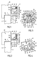
- la figure 1 est une vue partielle de côté, selon la flèche I de la figure 3, du guide-tringle, de l'ensemble de verrou et de la tringle du système selon l'invention dans un premier mode de réalisation, avec le guide-tringle monté sur un vantail et l'ensemble de verrou associé monté sur un montant d'huisserie avec son pêne en position passive ;
- la figure 2 est une vue analogue à la figure 1 avec le pêne en position active ;
- la figure 3 est une vue en perspective du guide-tringle et de l'ensemble de verrou du système selon l'invention dans le premier mode de réalisation, le pêne étant en position passive ;
- la figure 4 est une vue en perspective du guide-pêne du système selon l'invention dans une autre variante du premier mode de réalisation ;
- la figure 5 est une vue en coupe selon la ligne V -V de la figure 6 du guide-tringle et de l'ensemble de verrou du système selon l'invention dans le premier mode de réalisation, le pêne étant en position passive ;
- la figure 6 est une vue de face du guide -tringle et de l'ensemble de verrou du système selon l'invention dans le premier mode de réalisation, le pêne étant en position passive ;
- la figure 7 est une vue analogue à la figure 5 du système selon l'invention dans un deuxième mode de réalisation, le pêne étant en position passive ;
- la figure 8 est une vue en perspective du guide-tringle et de l'ensemble de verrou du système selon l'invention dans le deuxième mode de réalisation, l'élément fusible étant omis ;
- la figure 9 est une vue partielle en coupe, selon la ligne IX-IX de la figure 10, du guide-tringle, de l'ensemble de verrou et de la tringle du système selon l'invention dans un troisième mode de réalisation, avec le pêne en position passive ;
- la figure 10 est une vue partielle en coupe, selon la ligne X-X de la figure 9, du guide-tringle, de l'ensemble de verrou et de la tringle du système selon l'invention dans le troisième mode de réalisation, avec le pêne en position passive
- la figure 11 est une vue partielle en coup e, selon la ligne XI-XI de la figure 12, du guide-tringle, de l'ensemble de verrou et de la tringle du système selon l'invention dans un quatrième mode de réalisation, avec le pêne en position passive ;
- la figure 12 est une vue partielle en coupe, selon la ligne XII-XII de la figure 11, du guide-tringle, de l'ensemble de verrou et de la tringle du système selon l'invention dans le quatrième mode de réalisation, avec le pêne en position passive.
Claims (12)
- Système de verrouillage pour un ouvrant, ledit système comportant un ensemble de verrou (9, 109, 209, 309) et un ensemble de gâche (4, 104, 204, 304), l'un, dit premier, desdits deux ensembles étant destiné à être supporté par une face (2) d'un ouvrant (3), l'autre, dit second, desdits deux ensembles étant destiné à être supporté par un montant d'huisserie (20) dudit ouvrant ; ledit ensemble de gâche, en matière à haute température de fusion, comportant une première paroi de montage (10, 110, 210, 310), destinée à être fixée sur le support dudit ensemble de gâche, et une première paroi de guidage (12, 112, 212, 312) sensiblement perpendiculaire à ladite première paroi de montage et percée d'au moins un trou de gâche (38, 138, 238, 338), destiné à recevoir un pêne (29, 129, 229, 329) dudit ensemble de verrou ; ledit ensemble de verrou comprenant, d'une part, un guide-pêne (31, 131, 231, 331), en matière à haute température de fusion, comportant une seconde paroi de guidage (14, 114, 214, 314) et une seconde paroi de montage (13, 113, 213, 313) sensiblement perpendiculaires, ladite seconde paroi de montage étant destinée à être fixée sur le support dudit ensemble de verrou, de manière que lesdites première et seconde parois de guidage soient sensiblement en vis -à-vis lorsque ledit ouvrant est fermé, d'autre part, un pêne (29, 129, 229, 329), en matière à haute température de fusion, monté dans ledit guide - pêne avec une partie de blocage (33, 133, 23 3, 333) dudit pêne engagée dans au moins un trou de guidage (34, 134, 234, 334) ménagé dans ladite seconde paroi de guidage, de manière à être mobile entre une position passive, à laquelle ledit pêne est sensiblement rentré dans ledit guide-pêne pour permettre l'ouverture dudit ouvrant, et une position active, à laquelle ladite partie de blocage dudit pêne fait saillie par rapport à ladite seconde paroi de guidage pour s'engager dans ledit trou de gâche, ledit ensemble de verrou comportant un élément fusible (40, 140, 240, 340), en matière à basse température de fusion, ladite basse température de fusion étant comprise entre la température ambiante d'utilisation dudit ouvrant et ladite haute température de fusion, ledit élément fusible coopérant avec ledit pêne et ledit guide-pêne pour retenir ledit pêne à sa position passive à l'encontre de la gravité et/ou d'une force élastique, la fusion dudit élément fusible étant apte à libérer le déplacement dudit pêne vers sa position active pour bloquer ledit ouvrant en position fermée, caractérisé par le fait que ledit premier ensemble (4, 104, 204, 304) est destiné à être fixé sur ladite face d'ouvrant dans l'axe d'une tringle (1, 201, 301) fixée sur ladite face (2) d'ouvrant (3), ledit premier ensemble présentant une ouverture de guidage (6, 106, 206, 306) destinée à être traversée par ladite tringle pour pouvoir la guider en translation parallèlement à ladite face d'ouvrant, entre une position d'ouverture, dans laquelle ladite tringle est destinée à permettre l'ouverture dudit ouvrant, et une position de fermeture, dans laquelle une extrémité libre (5, 205, 305) de ladite tringle est destinée à faire saillie par rapport audit ouvrant ; ledit second ensemble (9, 109, 209, 309) étant destiné à être fixé sur ledit montant d'huisserie (20) au droit de ladite tringle pour fournir une gâche associée à ladite tringle, ledit second ensemble présentant un empennage (8, 108, 208, 308) pour pouvoir accueillir ladite extrémité libre de tringle à sa position de fermeture afin de maintenir ledit ouvrant en position fermée.
- Système de verrouillage selon la revendication 1, caractérisé par le fait que ledit pêne (29, 129, 229) comporte une partie centrale (30, 130, 230) sensiblement plane et deux branches (32, 132, 232), de longueurs sensiblement égales, liées sensiblement perpendiculairement aux extrémités longitudinales de celle -ci, lesdites deux branches formant ladite partie de blocage dudit pêne, ledit au moins un trou de guidage comportant deux lumières (34, 134, 234) parallèles dans lesquelles sont respectivement engagées lesdites deux branches pour y coulisser sensiblement perpendiculairement à ladite seconde paroi de guidage (14, 114, 214), ledit au moins un trou de gâche comportant également deux fentes (38, 138, 238) parallèl es pour recevoir lesdites deux branches à la position active dudit pêne ; ladite partie centrale venant en butée contre ledit guide -pêne à la position active dudit pêne.
- Système de verrouillage selon la revendication 2, caractérisé par le fait que ledit él ément fusible comporte une goupille (141) montée dans ledit pêne (129) sensiblement perpendiculairement auxdites branches (132) à travers deux trous débouchant (142) de celles-ci pour entraver son déplacement.
- Système de verrouillage selon l'une des revendications 2 ou 3, caractérisé par le fait que ledit ensemble de verrou (9,109,209) comporte un axe de guidage (25,125,225) sensiblement perpendiculaire à ladite partie centrale (30,130,230) du pêne (29,129,229) pour guider en translation ledit pêne, un ressort de compression (39,139,239) emmanché sur ledit axe de guidage étant, à la position passive dudit pêne, comprimé de manière à exercer ladite force élastique.
- Système de verrouillage selon la revendication 4, caractérisé par le fait que ledit élément fus ible comporte un manchon (40,240) emmanché sur ledit axe de guidage, pressé sous l'action dudit ressort (39,239)entre ladite partie centrale (30,230) du pêne (29, 229) et ledit guide-pêne (31,231).
- Système de verrouillage selon l'une des revendications 4 ou 5, caractérisé par le fait que ledit axe de guidage (225) est lié par une extrémité à ladite partie centrale (230) du pêne (229) et comporte un élargissement (249) à son autre extrémité pour retenir ledit ressort (239).
- Système de verrouillage selon l'une des revendications 4 ou 5, caractérisé par le fait que ledit axe de guidage (25, 125) est solidaire dudit guide-pêne (31, 131), ladite partie centrale (30, 130) du pêne (29, 129) étant traversée par ledit axe de guidage de manière coulissante.
- Système de verrouillage selon l'une des revendications 1 à 7, caractérisé par le fait que ledit guide -pêne (31, 131, 231, 331) comporte une plaque en forme de U avec deux ailes longitudinales (14, 15, 114, 115, 214, 215, 314, 315) repliées sensiblement perpendiculairement à une base centrale (13, 113, 213, 313), ladite base centrale formant ladite seconde paroi de montage, l'une (14, 114, 214, 314) desdites deux ailes formant ladite seconde paroi de guidage.
- Système de verrouillage selon l'une des revendications 1 à 8, caractérisé par le fait que ladite basse température de fusion est inférieure à 250°C, ladite matière à basse température de fusion étant par exemple un plastique, et que ladite haute température de fusion est supérieure à 950°C, ladite matière à haute température de fusion étant par exemple un acier ou un alliage de cuivre.
- Système de crémone et de gâche associée, caractérisé par le fait qu'il comprend un système de verrouillage selon l'une des revendications 1 à 9, ladite crémone comportant un mécanisme de manoeuvre destiné à être fixé sur ladite face (2) d'ouvrant (3) et ladite tringle (1, 201, 301), laquelle est apte à être déplacée sous l'action dudit mécanisme de manoeuvre entre ladite position d'ouverture et ladite position de fermeture, ledit second ensemble (9, 109, 209, 309) fournissant ladite gâche associée, ladite tringle étant en matière ayant une température de fusion intermédiaire, ladite température de fusion intermédiaire étant comprise entre ladite basse température de fusion et ladite haute température de fusion, de sorte qu'une élévation de la température ambiante soit apte à entraíner d'abord la fusion de l'élément fusible (40, 141, 240, 340) et le déplacement consécutif dudit pêne (29, 129, 229, 329) à sa position active pour bloquer ledit ouvrant en position fermée, même en cas de fusion ultérieure de ladite tringle.
- Système de crémone et de gâche associée selon la revendication 10, caractérisé par le fait que ledit système de verrouillage qu'il comporte est selon la revendication 2, ledit premier ensemble correspondant audit ensemble de gâche (4, 104, 204), ladite première paroi de guidage (12, 112, 212) comportant ladite ouverture de guidage (6, 106, 206), pour recevoir ladite tringle (1,201), sensiblement entre lesdites deux fentes parallèles (38, 138, 238), séparée de celles-ci ou d'un seul tenant avec elles, ledit second ensemble correspondant audit ensemble de verrou (9, 109, 209), ladite seconde paroi de guidage (14, 114, 214) comportant ledit empennage (8, 108, 208), pour recevoir ladite tringle, entre lesdites deux lumières parallèles (34, 134, 234), séparé de celles-ci ou d'un seul tenant avec elles.
- Système selon l'une des revendications 10 ou 11, caractérisé par le fait que ladite température de fusion intermédiaire de la tringle (1, 201, 301) est inférieure à 750°C, ladite matière à température de fusion intermédiaire étant par exemple de l'aluminium, dont la température de fusion est sensiblement égale à 732°C.
Applications Claiming Priority (2)
| Application Number | Priority Date | Filing Date | Title |
|---|---|---|---|
| FR0009903 | 2000-07-28 | ||
| FR0009903A FR2812332B1 (fr) | 2000-07-28 | 2000-07-28 | Systeme de verrouillage pour ouvrant devant resister au feu et systeme de cremone comportant un tel systeme de verrouillage |
Publications (2)
| Publication Number | Publication Date |
|---|---|
| EP1176277A1 EP1176277A1 (fr) | 2002-01-30 |
| EP1176277B1 true EP1176277B1 (fr) | 2005-05-18 |
Family
ID=8853013
Family Applications (1)
| Application Number | Title | Priority Date | Filing Date |
|---|---|---|---|
| EP20010401934 Expired - Lifetime EP1176277B1 (fr) | 2000-07-28 | 2001-07-19 | Crémone avec système de verrouillage pour porte coupe-feu |
Country Status (2)
| Country | Link |
|---|---|
| EP (1) | EP1176277B1 (fr) |
| FR (1) | FR2812332B1 (fr) |
Families Citing this family (1)
| Publication number | Priority date | Publication date | Assignee | Title |
|---|---|---|---|---|
| WO2013119795A1 (fr) * | 2012-02-10 | 2013-08-15 | Illinois Tool Works Inc. | Verrou de porte de sèche-linge actionné thermiquement |
Family Cites Families (3)
| Publication number | Priority date | Publication date | Assignee | Title |
|---|---|---|---|---|
| US4161804A (en) * | 1977-12-21 | 1979-07-24 | Rixson-Firemark, Inc. | Heat-actuated door latch |
| DE3315351A1 (de) * | 1983-04-28 | 1984-10-31 | Leininger-Brandschutzelemente GmbH, 5000 Köln | Selbsttaetig ausloesendes verriegelungselement fuer eine brandschutztuer |
| US5588686A (en) * | 1994-12-05 | 1996-12-31 | Adams Rite Manufacturing Company | Temperature responsive mechanism for controllably deadlocking a door to a door frame |
-
2000
- 2000-07-28 FR FR0009903A patent/FR2812332B1/fr not_active Expired - Fee Related
-
2001
- 2001-07-19 EP EP20010401934 patent/EP1176277B1/fr not_active Expired - Lifetime
Also Published As
| Publication number | Publication date |
|---|---|
| EP1176277A1 (fr) | 2002-01-30 |
| FR2812332B1 (fr) | 2003-06-13 |
| FR2812332A1 (fr) | 2002-02-01 |
Similar Documents
| Publication | Publication Date | Title |
|---|---|---|
| EP0963498B2 (fr) | Dispositif de fermeture pour porte | |
| EP1288405B1 (fr) | Ferrure de verrouillage pour ouvrant coulissant de porte, fenêtre ou analogue | |
| FR2777588A1 (fr) | Dispositif de verrouillage pour ouvrant coulissant | |
| EP1162334B1 (fr) | Serrure anti-glissement résistante au feu | |
| EP1176277B1 (fr) | Crémone avec système de verrouillage pour porte coupe-feu | |
| EP2098669B1 (fr) | Dispositif de guidage pour porte coulissante escamotable | |
| EP0869239B1 (fr) | Ferrure de verrouillage pour ouvrant coulissant de porte, fenêtre ou analogue | |
| EP0881347A1 (fr) | Ferrure de verrouillage pour ouvrant coulissant de porte, fenêtre ou analogue | |
| EP1176275B1 (fr) | Crémone avec système de blocage pour porte coupe-feu | |
| FR2867499A1 (fr) | Verrou de couverture de piscine | |
| FR2861789A1 (fr) | Serrure anti-panique multipoint reversible | |
| EP3404178A1 (fr) | Systeme de verrouillage au sol integre a un montant de portail | |
| EP0623837B1 (fr) | Charnière élastique de lunettes | |
| EP2586938B1 (fr) | Dispositif de verrouillage d'un ouvrant | |
| EP0919684B1 (fr) | Entrebaílleur | |
| FR2922933A1 (fr) | Dispositif de verrouillage d'elements ouvrants et fenetre comprenant un tel dispositif. | |
| EP1106752A1 (fr) | Serrure resistante au feu | |
| FR3019578A1 (fr) | Ferrure pour cadre profile comprenant une fixation elastique et coulissante | |
| FR2683579A1 (fr) | Agencement de verrouillage d'un organe mobile de fermeture d'une ouverture, telle qu'une porte. | |
| EP4026462A1 (fr) | Poignée amovible munie d'un organe d'appui renforce | |
| WO2017144811A1 (fr) | Systeme de verrouillage au sol integre a un montant de portail | |
| FR2575511A1 (fr) | Structure de mecanisme de fermeture, notamment pour portes d'equipements frigorifiques | |
| EP1908901A1 (fr) | Crémone, destinée à la manoeuvre d'ouverture et de fermeture d'un ouvrant | |
| FR2784132A1 (fr) | Ferrure de verrouillage pour ouvrant coulissant de porte, fenetre ou analogue | |
| FR2881779A1 (fr) | Poignee de manoeuvre |
Legal Events
| Date | Code | Title | Description |
|---|---|---|---|
| PUAI | Public reference made under article 153(3) epc to a published international application that has entered the european phase |
Free format text: ORIGINAL CODE: 0009012 |
|
| AK | Designated contracting states |
Kind code of ref document: A1 Designated state(s): AT BE CH CY DE DK ES FI FR GB GR IE IT LI LU MC NL PT SE TR Kind code of ref document: A1 Designated state(s): IT |
|
| AX | Request for extension of the european patent |
Free format text: AL;LT;LV;MK;RO;SI |
|
| 17P | Request for examination filed |
Effective date: 20020313 |
|
| AKX | Designation fees paid |
Free format text: IT |
|
| REG | Reference to a national code |
Ref country code: DE Ref legal event code: 8566 |
|
| RAP1 | Party data changed (applicant data changed or rights of an application transferred) |
Owner name: VACHETTE |
|
| GRAP | Despatch of communication of intention to grant a patent |
Free format text: ORIGINAL CODE: EPIDOSNIGR1 |
|
| GRAS | Grant fee paid |
Free format text: ORIGINAL CODE: EPIDOSNIGR3 |
|
| GRAA | (expected) grant |
Free format text: ORIGINAL CODE: 0009210 |
|
| AK | Designated contracting states |
Kind code of ref document: B1 Designated state(s): IT |
|
| REG | Reference to a national code |
Ref country code: IE Ref legal event code: FG4D Free format text: LANGUAGE OF EP DOCUMENT: FRENCH |
|
| PLBE | No opposition filed within time limit |
Free format text: ORIGINAL CODE: 0009261 |
|
| STAA | Information on the status of an ep patent application or granted ep patent |
Free format text: STATUS: NO OPPOSITION FILED WITHIN TIME LIMIT |
|
| 26N | No opposition filed |
Effective date: 20060221 |
|
| PGFP | Annual fee paid to national office [announced via postgrant information from national office to epo] |
Ref country code: IT Payment date: 20120726 Year of fee payment: 12 |
|
| PG25 | Lapsed in a contracting state [announced via postgrant information from national office to epo] |
Ref country code: IT Free format text: LAPSE BECAUSE OF NON-PAYMENT OF DUE FEES Effective date: 20130719 |