EP1176109A1 - Device for folding a sheet by means of a folding blade - Google Patents
Device for folding a sheet by means of a folding blade Download PDFInfo
- Publication number
- EP1176109A1 EP1176109A1 EP00116400A EP00116400A EP1176109A1 EP 1176109 A1 EP1176109 A1 EP 1176109A1 EP 00116400 A EP00116400 A EP 00116400A EP 00116400 A EP00116400 A EP 00116400A EP 1176109 A1 EP1176109 A1 EP 1176109A1
- Authority
- EP
- European Patent Office
- Prior art keywords
- sheet
- conveyor belts
- folding
- roller
- working area
- Prior art date
- Legal status (The legal status is an assumption and is not a legal conclusion. Google has not performed a legal analysis and makes no representation as to the accuracy of the status listed.)
- Granted
Links
Images


Classifications
-
- B—PERFORMING OPERATIONS; TRANSPORTING
- B65—CONVEYING; PACKING; STORING; HANDLING THIN OR FILAMENTARY MATERIAL
- B65H—HANDLING THIN OR FILAMENTARY MATERIAL, e.g. SHEETS, WEBS, CABLES
- B65H45/00—Folding thin material
- B65H45/12—Folding articles or webs with application of pressure to define or form crease lines
- B65H45/18—Oscillating or reciprocating blade folders
-
- B—PERFORMING OPERATIONS; TRANSPORTING
- B65—CONVEYING; PACKING; STORING; HANDLING THIN OR FILAMENTARY MATERIAL
- B65H—HANDLING THIN OR FILAMENTARY MATERIAL, e.g. SHEETS, WEBS, CABLES
- B65H29/00—Delivering or advancing articles from machines; Advancing articles to or into piles
- B65H29/68—Reducing the speed of articles as they advance
-
- B—PERFORMING OPERATIONS; TRANSPORTING
- B65—CONVEYING; PACKING; STORING; HANDLING THIN OR FILAMENTARY MATERIAL
- B65H—HANDLING THIN OR FILAMENTARY MATERIAL, e.g. SHEETS, WEBS, CABLES
- B65H2404/00—Parts for transporting or guiding the handled material
- B65H2404/50—Surface of the elements in contact with the forwarded or guided material
- B65H2404/56—Flexible surface
- B65H2404/561—Bristles, brushes
-
- B—PERFORMING OPERATIONS; TRANSPORTING
- B65—CONVEYING; PACKING; STORING; HANDLING THIN OR FILAMENTARY MATERIAL
- B65H—HANDLING THIN OR FILAMENTARY MATERIAL, e.g. SHEETS, WEBS, CABLES
- B65H2511/00—Dimensions; Position; Numbers; Identification; Occurrences
- B65H2511/50—Occurence
- B65H2511/51—Presence
Definitions
- the invention relates to a device for folding a Bow by means of a folding sword, with a conveyor belt and conveyor belt shafts feeding device for Transporting the sheet into the working area of the folding sword, the one between the conveyor belts located, an opening for the folding sword Inlet plate is formed under which the gap of a transport and folding roller pair is arranged with above the Feeding device arranged devices for holding down of the sheet and with at least one transverse to the sheet transport direction arranged stop for positioning the sheet in the Working area of the folding sword.
- the object underlying the invention is therefore in designing the device of the type mentioned at the outset in such a way that the sheet even at high transport speeds cannot jump back and crunch.
- the sheet is in front of the Stop, ideally just before the stop, slowed down, which precise positioning with regard to the folding blade is guaranteed.
- the device for Slow down the transport speed of the bow brushes which can be brought into frictional engagement with the surface of the bow are. It has been shown that the folding speed with 80g paper with the same folding quality of about Can increase from 110 m / min to 130 m / min.
- the brushes can be in their frictional engagement position with the Bow pre-tensioned.
- the brushes are expediently on the means for holding down the bow.
- the stop in the sheet transport direction is at least one Upstream sensor for detecting the feeding of a sheet, the device to slow down the transport speed of the bow activated.
- the device for slowing down the transport speed the sheet can be at least one over the transport plane the conveyor belts that can be raised for the sheet have, the means for holding down the sheet to maintain their engagement with the bow together can be raised with the guide device.
- the device for slowing down the transport speed the sheet can also be a device for lowering the conveyor belts have below the level of the inlet plate.
- the device for lowering the conveyor belts has an eccentric ligament tension shaft on that with the stop Conveyor belt shaft downstream in the sheet transport direction connected by a tensioning lever and between one of the Corresponding sheet transport position of the conveyor belts Position and one of the lowered position of the conveyor belts corresponding position is adjustable. That’s why Arch in contact with the inlet sheet and with the outside provided Guardrails, making it sufficient before the attack is braked.
- the above-described device for lowering the Conveyor belts can also be used with the arrangement mentioned Combine brushes for further braking of the bow.
- An alternative embodiment of the device according to the invention is that in the sheet transport direction before the Feeder for transporting the sheet into the work area of the folding sword another conveyor belt waves and sheet feeder having conveyor belts is arranged.
- the driving conveyor belt waves of the two A coupling is assigned to sheet feeding devices, which coupled the two sheet feeders for a synchronous operation connects and disengages the drive of the Conveyor belt shaft of the feed device for transport of the sheet in the work area of the folding sword.
- the sheet becomes even at high folding speed Gently brought up to the stop and can be so safe be aligned.
- the conveyor belts of the upstream Feeder must always run with it, so that a new bow can follow.
- the feed device extends for transport the sheet in the sheet transport direction in front of the work area of the folding sword.
- the conveyor belts are in front the working area of the folding sword laterally from Inlet sheet through a first roll from its sheet transport level to her lower run and through a second role run parallel to the lower run and above it and over a third role and a fourth role back in the plane of the upper run.
- the conveyor belts are then after moving around the work area of the folding sword Conveyor belt shaft downstream in the sheet transport direction are guided by a fifth role from the level of their lower run to her upper run and through a sixth Roll parallel to the upper run and below it and over a seventh role and an eighth role back into the Level of the lower run returned.
- the third role and the seventh roller is essentially parallel for movement for sheet transport direction with a common actuator connected.
- the actuator is so from the sensor controlled that the connected when detecting a sheet feeder Rolls are moved in the sheet transport direction, whereby through the third roll of tape length is drawn in without it the section of the conveyor belts in the working area of the folding sword pass.
- the seventh role gives the same Ratio of tape length drawn earlier back so that the sections of the conveyor belts before Working area of the folding blade with the transport speed of the arch continue to run while the work area sections of the conveyor belts associated with the folding blade stop briefly and brake the bow.
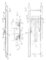
- the embodiment of the device shown in FIGS. 1 to 3 has two parallel conveyor belts 23a, which are for an endless Orbiting around two spaced conveyor belt shafts 20a and 20b are arranged. There is a between the conveyor belts 23a Inlet plate 25 and a 28 in the sheet transport direction (Arrow) extending opening 24 for the passage of the shown folding sword provided.
- the inlet plate 25 forms the working area of the folding sword.
- the end of the work area is limited by stops 29 by a cross member 54 are held and in the transport level 33 of a sheet 21 to be folded.
- the stops 29 are the end opposite the inlet side for the sheet 21 assigned to the opening 24.
- the embodiment of the device as shown in FIGS. 4 to 6 has a sensor 34 which is in the sheet transport direction 28 (arrow) at a distance of a few centimeters is arranged in front of the stops 29.
- Sensor 34 is ordinary a photocell that the leading edge of the tapered Sheet 21 detected and emits a corresponding signal.
- This Signal serves to activate a device 30 for slowing down of the bow 21 in front of the stops 29, which is in the design 4 to 6 by two lifting devices 39 for the bow 21 is reached, each of which has a long side is assigned to the opening 24 for the folding sword.
- the sheet 21 runs on two Inlet plate 25 associated inner conveyor belts 23a and on outer conveyor belts 20b, between which conductor devices 35 are arranged in the form of U-profiles.
- To Both sides of the opening 24 for the folding sword are in the Inlet plate 25 slots underneath the strips 32 recessed.
- Each lifting device 39 has a magnet 39c with an in its longitudinally reciprocable core rod on which an intermediate rod is articulated, which is fixed to a crossbar 39b is connected, which is transverse to the transport plane 33 of the Arch 21 extends and through openings in the vertical Flanges of the inlet plate 25 passes.
- a crossbar 39b On the crossbar 39b are levers 39a attached to a longitudinal displacement of the core rod of the magnet 39c and change their vertical position so that the Guide devices 35 and the strips 32 over the transport plane 33 of the arch 21, as shown in FIG. 5 is shown.
- the hold-down rollers 27a are thereby a magnet 27b also controlled by the sensor 34, however, the hold down engagement with the arch 21 preserved.
- the clutch 42 consists of a clutch roller 42a on the one leg of an angle lever articulated on the machine side 42c attacks, the other end with the core rod one Magnet 42e is hinged, the clutch roller 42a biased into its coupling position by a spring 42b is.
- the sensor 34 in the form of a photocell the leading edge of the incoming sheet 21 detected, it gives a signal to the Magnet 42e, which thereby runs its core rod in its longitudinal direction adjusted so that the frictional engagement of a clutch belt 24d that around the conveyor belt shaft 40e and Conveyor belt shaft 20a runs, is relaxed, causing the Conveyor belts 23a and 23b which run around in their longitudinal direction conveyor belt shaft 20a divided in the middle run to a standstill come.
- the bow 21 before the attacks 29 braked so that an impact on the stops 29 is prevented will while the working area of the folding sword 22 upstream feeder continues and then the next sheet can transport. With this configuration can the sheet 21 even at high folding speed gently brought up to the stops 29 and safely aligned become.
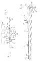
- FIGS. 9 and 10 has a work area the feed device, not shown, associated with the folding blade with two conveyor belt shafts 20a and 20b, around which two conveyor belts 23a circulate endlessly, and also outer conveyor belts, not shown, can be provided.
- the inlet plate 25 are assigned Strips 33 and, to the side thereof, guide devices 35 intended.
- Below the opening 24 in Fig. 9 is the pair of folding rollers 26, in the gap of which is not shown Folding sword folded by him through the opening 24 in the Inlet plate 25 introduces so that the arc between the rollers are folded and transported downwards.
- the working area of the folding sword in the direction of sheet travel 28 downstream conveyor belt shaft 20b is via a belt tensioning lever 5 connected to a belt tension shaft 4 so that based on a signal from the sensor 34 for the sheet feed the eccentrically formed band tension shaft 34 from one Motor is rotated by 180 °, whereby the ligament tensioning lever 38 with the conveyor belts 23a under the transport plane 33 be lowered.
- the sheet 21 thereby bumps gently against the Stops 29 and lies on the U-shaped guide devices 35 and on the strip 32 on the inlet plate 25.
- the ligament tensioning shaft 37 is turned through 180 ° rotated further so that the conveyor belts 23a again in the Transport level 33 lie.
- FIGS. 9 and 10 can be used for further braking Brush 31 against the strip 32, as in the Embodiment of FIGS. 1 to 3 and hold-down 24 in the form provided by retention brushes.
- the conveyor belt shaft 20a lies on the Feeder for the sheet far in front of the work area of the folding sword 22.
- the transbands 23a are in front of the work area the folding sword 22 deflected with the aid of rollers, in pairs, one on each side of the inlet plate 25 are provided so that the tape guide only is described using the one set of roles.
- the conveyor belt 23a After deflecting the conveyor belt 23a around the conveyor belt shaft 20b, the conveyor belt 23a becomes a fifth roller 47 deflected from the level of the lower run to the upper run and by a distance in the sheet transport direction 28 sixth roller 48 guided so that it is parallel to the upper run of the conveyor belt 23a below it opposite to the belt running direction 28 of the upper run to a seventh roll 49 is guided, which is arranged at a distance from the third roller 45 and the conveyor belt 23a to an eighth roller 50 deflects the conveyor belt 23a back into the plane of lower runs.
- the third roll 45 and the seventh roll 49 are by one Actuator 51 in the form of a rod rigidly together connected.
- the actuator 51 is at its free end in front of the conveyor belt shaft 20b with a linkage mechanism 51a connected to the one by a magnet 51b back and forth movable core hears.
- the sensor 34 When the sheet 21 reaches the sensor 34 with its front edge, the sensor 34 gives a signal to the magnet 51b which thereby actuating the linkage 50a so that the actuator 51 the third roller 45 and the rigidly connected seventh Roll 49 pulls in the sheet running direction 28.
- the third moves Roll 45 tape length without it to the working area of the Section 53 of the conveyor belts assigned to the folding sword 22 To pass on 23a.
- the seventh roller 49 gives the same ratio tape length previously drawn back again, see above that the section 52 of the conveyor belts 23a in front of the work area of the folding blade 52 at the same speed can continue to run.
- the section 53 of the conveyor belts 23a in The working area of the folding sword 22 comes to a brief standstill.
- Hold-down rollers 27a press via a sensor-controlled one Magnets 27b at the beginning of the work area of the folding sword 22 on the conveyor belts 23a, whereby the sheet 21st is also slowed down. In this way, the sheet 21 gently against the stops 29 even at high folding speed introduced and aligned safely.
Abstract
Description
Die Erfindung betrifft eine Vorrichtung zum Falzen eines Bogens mittels eines Falzschwertes, mit einer Transportbänder und Transportbandwellen aufweisenden Zuführeinrichtung zum Transportieren des Bogens in den Arbeitsbereich des Falzschwertes, der von einem sich zwischen den Transportbändern befindlichen, eine Öffnung für das Falzschwert aufweisenden Einlaufblech gebildet wird, unter der der Spalt eines Transport- und Falzwalzenpaares angeordnet ist, mit oberhalb der Zuführeinrichtung angeordneten Einrichtungen zum Niederhalten des Bogens und mit wenigstens einem quer zur Bogentransportrichtung angeordneten Anschlag zum Positionieren des Bogens im Arbeitsbereich des Falzschwertes.The invention relates to a device for folding a Bow by means of a folding sword, with a conveyor belt and conveyor belt shafts feeding device for Transporting the sheet into the working area of the folding sword, the one between the conveyor belts located, an opening for the folding sword Inlet plate is formed under which the gap of a transport and folding roller pair is arranged with above the Feeding device arranged devices for holding down of the sheet and with at least one transverse to the sheet transport direction arranged stop for positioning the sheet in the Working area of the folding sword.
Wenn die Bogentransportgeschwindigkeit geeignet eingestellt ist, kommt der Bogen am Anschlag zur Ruhe. Erhöht man die Bogentransportgeschwindigkeit, kommt es beim Aufprall an dem Anschlag zu einem Zurückfedern oder Verspringen des Bogens, so daß die richtige Ausrichtung unter dem Schwert nicht gewährleistet ist. Stark perforierte Bogen mit schmalen Verbindungsstegen vom Parallelbruch her sind hinsichtlich einer genauen Ausrichtung kaum beherrschbar. Je höher die Bogentransportgeschwindigkeit eingestellt wird und je labiler der Bogen ist, desto problematischer ist die genaue Bogenausrichtung am Anschlag.If the sheet transport speed is set appropriately the bow comes to rest at the stop. If you increase the Sheet transport speed, it comes to the impact Stop to spring back or jump off the bow, see above that proper alignment under the sword doesn't guarantee is. Heavily perforated arch with narrow connecting bars from the parallel break are accurate Alignment barely manageable. The higher the sheet transport speed is set and the more unstable the bow is, the more problematic is the precise sheet alignment on Attack.
Durch Verlangsamung der Schwertantriebszahl erhält der Bogen mehr Ausrichtezeit, was seine genaue Positionierung bezüglich des Falzschwertes begünstigt. By slowing the number of sword drives the bow receives more alignment time, regarding its precise positioning of the folding sword favored.
Um das Knautschen und Welligwerden des Bogens nach dem Anschlagaufprall zu vermeiden, hat man versucht, eine Kontrolle für das Zurückfedern des Bogens am Anschlag zu finden, beispielsweise durch eine bestimmte elastische Ausgestaltung des Anschlags. Dies erweist sich jedoch bei höheren Bogentransportgeschwindigkeiten als unzureichend.To make the bow crunch and curl after the impact to avoid trying to control for springing back of the bow at the stop, for example by a certain elastic design of the Attack. However, this proves to be the case at higher sheet transport speeds as inadequate.
Die der Erfindung zugrundeliegende Aufgabe besteht deshalb darin, die Vorrichtung der eingangs genannten Art so auszugestalten, daß der Bogen auch bei hohen Transportgeschwindigkeiten nicht vom Anschlag zurückspringen und knautschen kann.The object underlying the invention is therefore in designing the device of the type mentioned at the outset in such a way that the sheet even at high transport speeds cannot jump back and crunch.
Diese Aufgabe wird bei der eingangs genannten Vorrichtung durch wenigstens eine dem Anschlag in Bogentransportrichtung vorgeordnete Einrichtung zum Verlangsamen der Transportgeschwindigkeit des Bogens erreicht.This object is achieved with the device mentioned at the beginning by at least one of the stops in the sheet transport direction upstream device for slowing down the transport speed of the bow reached.
Mit der so ausgestalteten Vorrichtung wird der Bogen vor dem Anschlag, ideal erst kurz vor dem Anschlag, abgebremst, wodurch eine genaue Positionierung bezüglich des Falzschwerts gewährleistet ist.With the device designed in this way, the sheet is in front of the Stop, ideally just before the stop, slowed down, which precise positioning with regard to the folding blade is guaranteed.
In einer speziellen Ausgestaltung weist die Einrichtung zum Verlangsamen der Transportgeschwindigkeit des Bogens Bürsten auf, die mit der Bogenoberfläche in Reibungseingriff bringbar sind. Es hat sich gezeigt, daß sich dabei die Falzgeschwindigkeit mit einem 80g-Papier bei gleicher Falzqualität von etwa 110 m/min auf 130 m/min steigern läßt.In a special embodiment, the device for Slow down the transport speed of the bow brushes which can be brought into frictional engagement with the surface of the bow are. It has been shown that the folding speed with 80g paper with the same folding quality of about Can increase from 110 m / min to 130 m / min.
Die Bürsten können in ihre Reibungseingriffsstellung mit dem Bogen vorgespannt sein. Zweckmäßigerweise sind die Bürsten an den Einrichtungen zum Niederhalten des Bogens angeordnet.The brushes can be in their frictional engagement position with the Bow pre-tensioned. The brushes are expediently on the means for holding down the bow.
Damit der Bogen nicht unter die Transportebene der Transportbänder gedrückt wird, legt man auf das Einlaufblech sich in Bogentransportrichtung unterhalb der Bürsten erstreckende Streifen aus Blech oder einem anderen Material, deren Dicke so bemessen ist, daß ihre dem Bogen zugewandte Seite in der Transportebene der Transportbänder liegt.So that the sheet is not under the transport level of the conveyor belts is pressed, lie down on the inlet plate Sheet transport direction extending below the brushes Strips of sheet metal or other material, the thickness of which is so is dimensioned that its side facing the bow in the Transport level of the conveyor belts lies.
In weiterer Ausgestaltung der erfindungsgemäßen Vorrichtung ist dem Anschlag in Bogentransportrichtung wenigstens ein Sensor zum Erfassen der Zuführung eines Bogens vorgeordnet, der die Einrichtung zum Verlangsamen der Transportgeschwindigkeit des Bogens aktiviert.In a further embodiment of the device according to the invention the stop in the sheet transport direction is at least one Upstream sensor for detecting the feeding of a sheet, the device to slow down the transport speed of the bow activated.
Die Einrichtung zum Verlangsamen der Transportgeschwindigkeit des Bogens kann dabei wenigstens eine über die Transportebene der Transportbänder anhebbare Leiteinrichtung für den Bogen aufweisen, wobei die Einrichtungen zum Niederhalten des Bogens zur Aufrechterhaltung ihres Eingriffs mit dem Bogen gemeinsam mit der Leiteinrichtung anhebbar sind.The device for slowing down the transport speed the sheet can be at least one over the transport plane the conveyor belts that can be raised for the sheet have, the means for holding down the sheet to maintain their engagement with the bow together can be raised with the guide device.
Die Einrichtung zum Verlangsamen der Transportgeschwindigkeit des Bogens kann auch eine Einrichtung zum Absenken der Transportbänder unter die Ebene des Einlaufsblechs aufweisen.The device for slowing down the transport speed the sheet can also be a device for lowering the conveyor belts have below the level of the inlet plate.
Die Einrichtung zum Absenken der Transportbänder weist dabei eine exzentrische Bänderspannwelle auf, die mit der dem Anschlag in Bogentransportrichtung nachgeordneten Transportbandwelle über Bänderspannhebel verbunden und zwischen einer der Bogentransportstellung der Transportbänder entsprechenden Position und einer der abgesenkten Stellung der Transportbänder entsprechenden Position verstellbar ist. Dadurch kommt der Bogen in Kontakt mit dem Einlaufblech und mit außen vorgesehenen Leitschienen, wodurch er vor dem Anschlag ausreichend abgebremst wird. The device for lowering the conveyor belts has an eccentric ligament tension shaft on that with the stop Conveyor belt shaft downstream in the sheet transport direction connected by a tensioning lever and between one of the Corresponding sheet transport position of the conveyor belts Position and one of the lowered position of the conveyor belts corresponding position is adjustable. That’s why Arch in contact with the inlet sheet and with the outside provided Guardrails, making it sufficient before the attack is braked.
Die vorstehend beschriebene Einrichtung zum Absenken der Transportbänder läßt sich auch mit der erwähnten Anordnung der Bürsten für eine weiteres Abbremsen des Bogens kombinieren.The above-described device for lowering the Conveyor belts can also be used with the arrangement mentioned Combine brushes for further braking of the bow.
Eine alternative Ausgestaltung der erfindungsgemäßen Vorrichtung besteht darin, daß in Bogentransportrichtung vor der Zuführeinrichtung zum Transportieren des Bogens in den Arbeitsbereich des Falzschwertes eine weitere Transportbandwellen und Transportbänder aufweisende Bogenzuführeinrichtung angeordnet ist. Den treibenden Transportbandwellen der beiden Bogenzuführungseinrichtungen ist dabei eine Kupplung zugeordnet, die eingekuppelt die beiden Bogenzuführeinrichtungen für einen Synchronlauf verbindet und ausgekoppelt den Antrieb der Transportbandwelle der Zuführeinrichtung zum Transportieren des Bogens in den Arbeitsbereich des Falzschwertes unterbricht. Der Bogen wird dadurch auch bei hoher Falzgeschwindigkeit sanft an den Anschlag herangeführt und kann so sicher ausgerichtet werden. Die Transportbänder der vorgeordneten Zuführeinrichtung müssen immer mitlaufen, damit bereits ein neuer Bogen nachkommen kann.An alternative embodiment of the device according to the invention is that in the sheet transport direction before the Feeder for transporting the sheet into the work area of the folding sword another conveyor belt waves and sheet feeder having conveyor belts is arranged. The driving conveyor belt waves of the two A coupling is assigned to sheet feeding devices, which coupled the two sheet feeders for a synchronous operation connects and disengages the drive of the Conveyor belt shaft of the feed device for transport of the sheet in the work area of the folding sword. As a result, the sheet becomes even at high folding speed Gently brought up to the stop and can be so safe be aligned. The conveyor belts of the upstream Feeder must always run with it, so that a new bow can follow.
Bei einer weiteren Ausgestaltung der erfindungsgemäßen Vorrichtung erstreckt sich die Zuführeinrichtung zum Transportieren des Bogens in Bogentransportrichtung vor den Arbeitsbereich des Falzschwerts. Dabei werden die Transportbänder vor dem Arbeitsbereich des Falzschwerts jeweils seitlich vom Einlaufblech durch eine erste Rolle aus ihrer Bogentransportebene zu ihrem unteren Trum hin und durch eine zweite Rolle parallel zum unteren Trum und oberhalb davon geführt und über eine dritte Rolle und eine vierte Rolle wieder in die Ebene des oberen Trums zurückgeführt. Die Transportbänder werden dann, nachdem sie um die dem Arbeitsbereich des Falzschwerts in Bogentransportrichtung nachgeordnete Transportbandwelle geführt sind, durch eine fünfte Rolle aus der Ebene ihres unteren Trums zu ihrem oberen Trum hin und durch eine sechste Rolle parallel zum oberen Trum und unterhalb davon geführt und über eine siebente Rolle und eine achte Rolle wieder in die Ebene des unteren Trums zurückgeführt. Die dritte Rolle und die siebte Rolle sind für eine Bewegung im wesentlichen parallel zur Bogentransportrichtung mit einem gemeinsamen Betätigungsglied verbunden. Das Betätigungsglied wird vom Sensor so gesteuert, daß bei Erfassen einer Bogenzuführung die verbundenen Rollen in Bogentransportrichtung bewegt werden, wodurch durch die dritte Rolle Bandlänge eingezogen wird, ohne sie an den Abschnitt der Transportbänder im Arbeitsbereich des Falzschwerts weiterzugeben. Die siebte Rolle gibt dabei im gleichen Verhältnis bereits früher eingezogene Bandlänge wieder zurück, so daß die Abschnitte der Transportbänder vor dem Arbeitsbereich des Falzschwerts mit der Transportgeschwindigkeit des Bogens weiterlaufen, während die dem Arbeitsbereich des Falzschwerts zugeordneten Abschnitte der Transportbänder kurz zum Stehen kommen und den Bogen abbremsen. Danach werden die verbundenen Rollen in ihre Ausgangsstellung unter Beschleunigung der dem Arbeitsbereich des Falzschwerts zugeordneten Abschnitte der Transportbänder zurückbewegt.In a further embodiment of the device according to the invention the feed device extends for transport the sheet in the sheet transport direction in front of the work area of the folding sword. The conveyor belts are in front the working area of the folding sword laterally from Inlet sheet through a first roll from its sheet transport level to her lower run and through a second role run parallel to the lower run and above it and over a third role and a fourth role back in the plane of the upper run. The conveyor belts are then after moving around the work area of the folding sword Conveyor belt shaft downstream in the sheet transport direction are guided by a fifth role from the level of their lower run to her upper run and through a sixth Roll parallel to the upper run and below it and over a seventh role and an eighth role back into the Level of the lower run returned. The third role and the seventh roller is essentially parallel for movement for sheet transport direction with a common actuator connected. The actuator is so from the sensor controlled that the connected when detecting a sheet feeder Rolls are moved in the sheet transport direction, whereby through the third roll of tape length is drawn in without it the section of the conveyor belts in the working area of the folding sword pass. The seventh role gives the same Ratio of tape length drawn earlier back so that the sections of the conveyor belts before Working area of the folding blade with the transport speed of the arch continue to run while the work area sections of the conveyor belts associated with the folding blade stop briefly and brake the bow. After that the connected roles in their starting position under acceleration the assigned to the work area of the folding sword Sections of the conveyor belts moved back.
Vorteilhafterweise werden nur die inneren Transportbänder in dieser Weise geführt, während zusätzlich äußere Transportbänder vorgesehen werden können, denen eine vorstehend beschriebene Leiteinrichtung zugeordnet werden kann.Advantageously, only the inner conveyor belts in this way, while additionally outer conveyor belts can be provided, which one described above Control device can be assigned.
Anhand von Zeichnungen werden Ausführungsbeispiele der Erfindung näher erläutert. Es zeigen
- Fig. 1
- einen Querschnitt durch eine erste Ausführungsform der Vorrichtung,
- Fig. 2
- die Vorrichtung von Fig. 1 im Längsschnitt,
- Fig. 3
- die Vorrichtung von Fig. 1 in der Draufsicht,
- Fig. 4
- eine zweite Ausführungsform der Vorrichtung im Querschnitt,
- Fig. 5
- die Ausführungsform von Fig. 4 im Längsschnitt,
- Fig. 6
- in einer Ansicht wie Fig. 5 eine Einzelheit der Vorrichtung,
- Fig. 7
- eine dritte Ausführungsform der Vorrichtung im Längsschnitt,
- Fig. 8
- die Vorrichtung von Fig. 7 in der Draufsicht,
- Fig. 9
- eine vierte Ausführungsform der Vorrichtung im Querschnitt,
- Fig. 10
- die Vorrichtung von Fig. 9 im Längsschnitt,
- Fig. 11
- eine fünfte Ausführungsform der Vorrichtung im Querschnitt,
- Fig. 12
- die Vorrichtung von Fig. 11 im Längsschnitt und
- Fig. 13
- die Vorrichtung von Fig. 12 in der Draufsicht.
- Fig. 1
- 3 shows a cross section through a first embodiment of the device,
- Fig. 2
- 1 in longitudinal section,
- Fig. 3
- 1 in top view,
- Fig. 4
- a second embodiment of the device in cross section,
- Fig. 5
- 4 in longitudinal section,
- Fig. 6
- 5 shows a detail of the device,
- Fig. 7
- a third embodiment of the device in longitudinal section,
- Fig. 8
- 7 the device of FIG. 7 in plan view,
- Fig. 9
- a fourth embodiment of the device in cross section,
- Fig. 10
- 9 in longitudinal section,
- Fig. 11
- a fifth embodiment of the device in cross section,
- Fig. 12
- 11 in longitudinal section and
- Fig. 13
- the device of Fig. 12 in plan view.
Die in Fig. 1 bis 3 gezeigte Ausführungsform der Vorrichtung
hat zwei parallele Transportbänder 23a, die für einen endlosen
Umlauf um zwei beabstandete Transportbandwellen 20a und 20b
angeordnet sind. Zwischen den Transportbändern 23a ist ein
Einlaufblech 25 und eine sich in Bogentransportrichtung 28
(Pfeil) erstreckende Öffnung 24 für den Durchgang des nicht
gezeigten Falzschwerts vorgesehen. Das Einlaufblech 25 bildet
den Arbeitsbereich des Falzschwerts. Das Ende des Arbeitsbereichs
wird von Anschlägen 29 begrenzt, die von einem Querträger
54 gehalten werden und sich in die Transportebene 33
eines zu falzenden Bogens 21 erstrecken. Die Anschläge 29 sind
dem der Zulaufseite für den Bogen 21 gegenüberliegenden Ende
der Öffnung 24 zugeordnet.The embodiment of the device shown in FIGS. 1 to 3
has two
Auf dem Einlaufblech 25 sind parallel zu den Transportbändern
23a Streifen 24 aus Blech oder Kunststoff angeordnet, die mit
ihrer dem Bogen 21 zugewandten Seite in der Transportebene 33
liegen. Oberhalb der Streifen 32 sind zu beiden Seiten der
Öffnung 24 Bürsten 31 vorgesehen, die an Einrichtungen 27 zum
Niederhalten des Bogens 21 festgelegt sind. Die Festlegung der
Bürsten 31 an der Einrichtung 27 zum Niederhalten des Bogens
21 kann als Gelenk ausgebildet sein, wobei nicht gezeigte
Torsionsfedern die Bürsten 31 in die Reibungseingriffsstellung
mit der Bogenoberseite vorspannen. Als Einrichtungen 27 zum
Niederhalten des Bogens 21 sind ferner Niederhalteleisten
vorgesehen, die sich in Bogentransportrichtung 28 erstrecken.
Die Abbremsung des Bogens 21 erfolgt dadurch, daß die Bürsten
31 auf die Oberseite des Bogens 21 drücken, der auf seiner
Unterseite durch die den Bürsten 31 zugeordnete Streifen 32
abgestützt ist.On the
Die Ausführungsform der Vorrichtung, wie sie in Fig. 4 bis 6
gezeigt ist, hat einen Sensor 34, der in Bogentransportrichtung
28 (Pfeil) in einer Entfernung von wenigen Zentimetern
vor den Anschlägen 29 angeordnet ist. Der Sensor 34 ist gewöhnlich
eine Photozelle, die die Vorderkante des zulaufenden
Bogens 21 erfaßt und ein entsprechendes Signal abgibt. Dieses
Signal dient zur Aktivierung einer Einrichtung 30 zum Verlangsamen
des Bogens 21 vor den Anschlägen 29, was in der Ausgestaltung
von Fig. 4 bis 6 durch zwei Hubeinrichtungen 39 für
den Bogen 21 erreicht wird, von denen jede einer Längsseite
der Öffnung 24 für das Falzschwert zugeordnet ist.The embodiment of the device as shown in FIGS. 4 to 6
has a
Wie aus Fig. 4 zu sehen ist, läuft der Bogen 21 auf zwei dem
Einlaufblech 25 zugeordneten inneren Transportbändern 23a und
auf äußeren Transportbändern 20b, zwischen denen Leitereinrichtungen
35 in Form von U-Profilen angeordnet sind. Zu
beiden Seiten der Öffnung 24 für das Falzschwert sind in dem
Einlaufblech 25 Schlitze unterhalb der Streifen 32 ausgespart.As can be seen from Fig. 4, the
Jede Hubeinrichtung 39 hat einen Magneten 39c mit einem in
seiner Längsrichtung hin und her bewegbaren Kernstab, an dem
ein Zwischenstab angelenkt ist, der fest mit einer Querstange
39b verbunden ist, die sich quer zur Transportebene 33 des
Bogens 21 erstreckt und durch Öffnungen in den vertikalen
Flanschen des Einlaufsblechs 25 hindurchgeht. An der Querstange
39b sind Hebel 39a befestigt, die bei einer Längsverschiebung
des Kernstabs des Magneten 39c geschwenkt werden und
dabei ihre vertikale Position so verändern, daß sich die
Leiteinrichtungen 35 und die Streifen 32 über die Transportebene
33 des Bogens 21 anheben lassen, wie dies in Fig. 5
gezeigt ist. Dabei werden die Niederhalterollen 27a durch
einen ebenfalls vom Sensor 34 gesteuerten Magenten 27b angehoben,
wobei jedoch der Niederhalteeingriff mit dem Bogen 21
erhalten bleibt.Each lifting
Dadurch, daß der Bogen 21 von den Leiteinrichtungen 35 und den
Streifen 32 über die Transportebene 33 der Transportbänder 23a
und 23b angehoben wird, kann er von ihnen nicht weiter transportiert
werden. Er wird also abgebremst, wobei der Vorgang so
dosiert ist, daß der Bogen 21 möglichst sanft an den Anschlägen
29 anstößt.In that the
Bei der Ausführungsform der Fig. 7 und 8 ist in Bogentransportrichtung
28 der Zuführeinrichtung im Arbeitsbereich des
Falzschwerts 22 eine weitere Zuführeinrichtung vorgeordnet,
die Transportbänder 41a, 41b und Transportbandwellen 40a und
40b aufweist, wobei sich die Achse der letzteren parallel zur
Achse der Transportbandwelle 20a in der gleichen Horizontalebene
erstreckt. Die Transportbandwellen 40b und 20a sind
durch eine Kupplung 42 so verbindbar, daß sie synchron laufen
und so trennbar, daß die dem Arbeitsbereich des Falzschwerts
23 zugeordnete Zuführeinrichtung für den Bogen 21 stillsteht.7 and 8 is in the
Die Kupplung 42 besteht aus einer Kupplungsrolle 42a, an der
der eine Schenkel eines maschinenseitig angelenkten Winkelhebels
42c angreift, dessen anderes Ende mit dem Kernstab eines
Magneten 42e gelenkig verbunden ist, wobei die Kupplungsrolle
42a durch eine Feder 42b in ihre Kupplungsstellung vorgespannt
ist.The clutch 42 consists of a
Wenn der Sensor 34 in Form einer Photozelle die Vorderkante
des zulaufenden Bogens 21 erfaßt, gibt sie ein Signal an den
Magneten 42e, der dadurch seinen Kernstab in seiner Längsrichtung
so verstellt, daß der Reibungseingriff eines Kupplungsbandes
24d, das um die Transportbandwelle 40e und die
Transportbandwelle 20a läuft, entspannt wird, wodurch die
Transportbänder 23a und 23b, die um die in ihrer Längsrichtung
mittig geteilte Transportbandwelle 20a laufen, zum Stillstand
kommen. Auf diese Weise wird der Bogen 21 vor den Anschlägen
29 abgebremst, so daß ein Aufprall auf die Anschläge 29 unterbunden
wird, während die dem Arbeitsbereich des Falzschwerts
22 vorgeordnete Zuführeinrichtung weiterläuft und dann den
nächstfolgenden Bogen transportieren kann. Bei dieser Ausgestaltung
kann der Bogen 21 auch bei hoher Falzgeschwindigkeit
sanft an die Anschläge 29 herangeführt und sicher ausgerichtet
werden.If the
Die Ausführungsform von Fig. 9 und 10 hat eine dem Arbeitsbereich
des nicht gezeigten Falzschwertes zugeordnete Zuführeinrichtung
mit zwei Transportbandwellen 20a und 20b, um die
zwei Transportbänder 23a endlos umlaufen, wobei auch noch
äußere nicht gezeigte Transportbänder vorgesehen werden können.
In der Transportebene 33 sind dem Einlaufblech 25 zugeordnete
Streifen 33 und seitlich davon Leiteinrichtungen 35
vorgesehen. Unterhalb der Öffnung 24 ist in Fig. 9 das Falzwalzenpaar
26 gezeigt, in dessen Spalt das nicht gezeigte
Falzschwert den von ihm gefalzen Bogen durch die Öffnung 24 im
Einlaufblech 25 hindurch einführt, so daß der Bogen zwischen
den Walzen gefalzt und nach unten transportiert wird.The embodiment of FIGS. 9 and 10 has a work area
the feed device, not shown, associated with the folding blade
with two
Die dem Arbeitsbereich des Falzschwerts in Bogenlaufrichtung
28 nachgeordnete Transportbandwelle 20b ist über einen Bänderspannhebel
5 mit einer Bänderspannwelle 4 so verbunden, daß
aufgrund eines Signals aus dem Sensor 34 für den Bogenzulauf
die exzentrisch ausgewbildete Bänderspannwelle 34 von einem
Motor um 180° gedreht wird, wodurch die Bänderspannhebel 38
mit den Transportbändern 23a unter die Transportebene 33
abgesenkt werden. Der Bogen 21 stößt dadurch sanft gegen die
Anschläge 29 und liegt auf den U-förmigen Leiteinrichtungen 35
und auf den Streifen 32 auf dem Einlaufblech 25. Bevor der
nächste Bogen ankommt, wird die Bänderspannwelle 37 um 180°
weitergedreht, so daß die Transportbänder 23a wieder in der
Transportebene 33 liegen.The working area of the folding sword in the direction of
Wie aus Fig. 9 und 10 zu sehen ist, können zur weiteren Abbremsung
Bürsten 31 gegenüber dem Streifen 32, wie bei der
Ausführungsform der Fig. 1 bis 3 sowie Niederhalter 24 in Form
von Rückhaltebürsten vorgesehen werden.As can be seen from FIGS. 9 and 10, can be used for
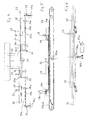
Bei der Ausführungsform der Vorrichtung, wie sie in Fig. 11
bis 13 gezeigt ist, liegt die Transportbandwelle 20a der
Zuführeinrichtung für den Bogen weit vor dem Arbeitsbereich
des Falzschwerts 22. Die Transbänder 23a werden vor dem Arbeitsbereich
des Falzschwertes 22 mit Hilfe von Rollen umgelenkt,
die jeweils paarweise, eine auf jeder Seite des Einlaufsblech
25 vorgesehen sind, so daß die Bandführung nur
anhand des einen Rollensatzes beschrieben wird.In the embodiment of the device as shown in FIG. 11
13 to 13, the
Vor dem Arbeitsbereich des Falzschwerts 22 wird das obere Trum
des Transportbandes 23a um eine erste Rolle 43 nach unten zum
unteren Trum des Transportbandes 23a hin umgelenkt und über
eine zweite Rolle 24 parallel zum unteren Ende des Transportbandes
23a, jedoch oberhalb davon zu einer dritten Rolle 45
geführt, um die herum das Transportband 23a entgegen der
Bandlaufrichtung 28 seines oberen Trums zurück um eine vierte
Rolle 46 nach oben wieder in die Transportebene 33 geführt
wird.In front of the working area of the
Nach dem Umlenken des Transportbandes 23a um die Transportbandwelle
20b wird das Transportband 23a um eine fünfte Rolle
47 aus der Ebene des unteren Trums zum oberen Trum hin umgelenkt
und um eine in Bogentransportrichtung 28 beabstandete
sechste Rolle 48 geführt, so daß es parallel zum oberen Trum
des Transportbandes 23a unterhalb davon entgegen der Bandlaufrichtung
28 des oberen Trums zu einer siebten Rolle 49
geführt wird, die im Abstand von der dritten Rolle 45 angeordnet
ist und das Transportband 23a zu einer achten Rolle 50
umlenkt, die das Transportband 23a wieder in die Ebene des
unteren Trums zurückführt.After deflecting the
Die dritte Rolle 45 und die siebte rolle 49 sind durch ein
Betätigungsglied 51 in Form einer Stange starr miteinander
verbunden. Das Betätigungsglied 51 ist an seinem freien Ende
vor der Transportbandwelle 20b mit einem Gestängemechanismus
51a verbunden, zu dem ein von einem Magneten 51b hin und her
verschiebbarer Kernstdab gehört. The
Wenn der Bogen 21 mit seiner Vorderkante den Sensor 34 erreicht,
gibt der Sensor 34 ein Signal an den Magneten 51b, der
dadurch das Gestänge 50a so betätigt, daß das Betätigungsglied
51 die dritte Rolle 45 und die starr damit verbundene siebte
Rolle 49 in Bogenlaufrichtung 28 zieht. Dabei zieht die dritte
Rolle 45 Bandlänge ein, ohne sie an den dem Arbeitsbereich des
Falzschwerts 22 zugeordneten Abschnitt 53 der Transportbänder
23a weiterzugeben. Die siebte Rolle 49 gibt im gleichen Verhältnis
bereits früher eingezogene Bandlänge wieder zurück, so
daß der Abschnitt 52 der Transportbänder 23a vor dem Arbeitsbereich
des Falzschwerts 52 mit gleicher Geschwindigkeit
weiterlaufen kann. Der Abschnitt 53 der Transportbänder 23a im
Arbeitsbereich des Falzschwerts 22 kommt so kurz zum Stehen.
Dabei drücken Niederhalterollen 27a über einen sensorgesteuerten
Magneten 27b zu Beginn des Arbeitsbereichs des Falzschwerts
22 auf die Transportbänder 23a, wodurch der Bogen 21
ebenfalls abgebremst wird. Auf diese Weise kann der Bogen 21
auch bei hoher Falzgeschwindigkeit sanft an die Anschläge 29
herangeführt und sicher ausgerichtet werden.When the
Wenn das Falzschwert 22 den Bogen 21 übernommen hat, wirkt der
Magnet 51b in entgegengesetzter Richtung, wodurch die dritte
Rolle 45 und die siebte Rolle 49 entgegen der Bogenlaufrichtung
28 verschoben werden, wobei der dem Arbeitsbereich des
Falzschwerts 22 zugeordnete Abschnitt 53 der Transportbänder
23a kurz schneller als normal läuft.If the
Wenn nicht gezeigte äußere Transportbänder vorhanden sind,
kann diesen die in Fig. 4 bis 6 gezeigte Hubeinrichtung 36 für
die Leiteinrichtungen 35 zugeordnet werden.If there are outer conveyor belts, not shown,
can this the lifting
Claims (13)
Priority Applications (2)
| Application Number | Priority Date | Filing Date | Title |
|---|---|---|---|
| DE50003905T DE50003905D1 (en) | 2000-07-28 | 2000-07-28 | Device for folding a sheet using a folding sword |
| EP20000116400 EP1176109B1 (en) | 2000-07-28 | 2000-07-28 | Device for folding a sheet by means of a folding blade |
Applications Claiming Priority (1)
| Application Number | Priority Date | Filing Date | Title |
|---|---|---|---|
| EP20000116400 EP1176109B1 (en) | 2000-07-28 | 2000-07-28 | Device for folding a sheet by means of a folding blade |
Publications (2)
| Publication Number | Publication Date |
|---|---|
| EP1176109A1 true EP1176109A1 (en) | 2002-01-30 |
| EP1176109B1 EP1176109B1 (en) | 2003-10-01 |
Family
ID=8169385
Family Applications (1)
| Application Number | Title | Priority Date | Filing Date |
|---|---|---|---|
| EP20000116400 Expired - Lifetime EP1176109B1 (en) | 2000-07-28 | 2000-07-28 | Device for folding a sheet by means of a folding blade |
Country Status (2)
| Country | Link |
|---|---|
| EP (1) | EP1176109B1 (en) |
| DE (1) | DE50003905D1 (en) |
Cited By (2)
| Publication number | Priority date | Publication date | Assignee | Title |
|---|---|---|---|---|
| EP1475338A1 (en) * | 2003-05-08 | 2004-11-10 | MASCHINENBAU OPPENWEILER BINDER GmbH & Co. KG | Knife folding machine |
| EP1900660A2 (en) * | 2006-09-13 | 2008-03-19 | Heidelberger Druckmaschinen AG | Device for positioning the trailing edge of sheets |
Citations (3)
| Publication number | Priority date | Publication date | Assignee | Title |
|---|---|---|---|---|
| US4573671A (en) * | 1984-05-07 | 1986-03-04 | Harris-Marinoni S.A. | Automatic setting device for slowing down a signature prior to folding in printing press chopper folders |
| US4746108A (en) * | 1985-12-04 | 1988-05-24 | Komori Printing Machinery Co., Ltd. | Chopper device for use in a folder |
| US5405127A (en) * | 1993-04-14 | 1995-04-11 | Didde Web Press Corporation | Signature folder apparatus for web fed printing press with sheet stop adjustment |
-
2000
- 2000-07-28 EP EP20000116400 patent/EP1176109B1/en not_active Expired - Lifetime
- 2000-07-28 DE DE50003905T patent/DE50003905D1/en not_active Expired - Lifetime
Patent Citations (3)
| Publication number | Priority date | Publication date | Assignee | Title |
|---|---|---|---|---|
| US4573671A (en) * | 1984-05-07 | 1986-03-04 | Harris-Marinoni S.A. | Automatic setting device for slowing down a signature prior to folding in printing press chopper folders |
| US4746108A (en) * | 1985-12-04 | 1988-05-24 | Komori Printing Machinery Co., Ltd. | Chopper device for use in a folder |
| US5405127A (en) * | 1993-04-14 | 1995-04-11 | Didde Web Press Corporation | Signature folder apparatus for web fed printing press with sheet stop adjustment |
Cited By (4)
| Publication number | Priority date | Publication date | Assignee | Title |
|---|---|---|---|---|
| EP1475338A1 (en) * | 2003-05-08 | 2004-11-10 | MASCHINENBAU OPPENWEILER BINDER GmbH & Co. KG | Knife folding machine |
| CN100336708C (en) * | 2003-05-08 | 2007-09-12 | 奥彭魏勒宾德尔机械制造公司 | Knife type folding device |
| EP1900660A2 (en) * | 2006-09-13 | 2008-03-19 | Heidelberger Druckmaschinen AG | Device for positioning the trailing edge of sheets |
| EP1900660A3 (en) * | 2006-09-13 | 2008-12-17 | Heidelberger Druckmaschinen AG | Device for positioning the trailing edge of sheets |
Also Published As
| Publication number | Publication date |
|---|---|
| EP1176109B1 (en) | 2003-10-01 |
| DE50003905D1 (en) | 2003-11-06 |
Similar Documents
| Publication | Publication Date | Title |
|---|---|---|
| DE2518373C2 (en) | Device for equalizing the mutual distances between printed products following one another in an imbricated flow | |
| EP0073388B1 (en) | Device for changing the direction of transport of letters and similar rectangular articles | |
| DE3700959C2 (en) | Sheet collecting device | |
| DE19955815A1 (en) | Sheet separator for compiling of printed sheets for e.g. magazines has rotating separator rollers with defined movement tracks and separator wedge | |
| DE4225607A1 (en) | REVERSIBLE COLLATION MACHINE | |
| EP0055405B1 (en) | Set of moving tapes for feeding folded articles and for reducing the speed thereof | |
| EP0473902A1 (en) | Device for stapling multiple-part printed products | |
| CH634278A5 (en) | FOLDING APPARATUS. | |
| DE2539799B2 (en) | Blueprint machine with a repeating device | |
| DE4201256C2 (en) | Method and device for producing individual stacks of paper, approximately half, simply V-shaped, mutually nested cigarette papers | |
| EP0205116B1 (en) | Folding machine | |
| EP0091582B1 (en) | Device for drawing asunder piles of folded products mutually staggered transversely to the direction of transport | |
| EP1196345B1 (en) | Method and device for the overlapping arrangement of at least two sheets | |
| EP1176109B1 (en) | Device for folding a sheet by means of a folding blade | |
| EP1494946B1 (en) | Device for aligning sheets and a method for aligning sheets transversal to the direction of travel of the sheets | |
| DE19627490A1 (en) | Conveyor for printed matter | |
| DE4207069A1 (en) | DEVICE FOR GUIDING LEAVES TO A STORAGE AREA | |
| EP1944257B1 (en) | Device for lateral alignment of printed products | |
| EP2316767B1 (en) | Device and method for manufacturing printed product stacks | |
| EP1169251B1 (en) | Device for transferring products between conveyor parts | |
| DE102008007965B4 (en) | Falztaschenvorrichtung | |
| DE4012517A1 (en) | FOLDING AND FEEDING DEVICE | |
| DE10059587A1 (en) | Method and device for folding sheets of material | |
| DE3919436C2 (en) | ||
| DE4447541C2 (en) | Device for the lateral alignment of sheets |
Legal Events
| Date | Code | Title | Description |
|---|---|---|---|
| PUAI | Public reference made under article 153(3) epc to a published international application that has entered the european phase |
Free format text: ORIGINAL CODE: 0009012 |
|
| AK | Designated contracting states |
Kind code of ref document: A1 Designated state(s): AT BE CH CY DE DK ES FI FR GB GR IE IT LI LU MC NL PT SE Kind code of ref document: A1 Designated state(s): DE FR GB IT |
|
| AX | Request for extension of the european patent |
Free format text: AL;LT;LV;MK;RO;SI |
|
| 17P | Request for examination filed |
Effective date: 20020315 |
|
| AKX | Designation fees paid |
Free format text: DE FR GB IT |
|
| GRAH | Despatch of communication of intention to grant a patent |
Free format text: ORIGINAL CODE: EPIDOS IGRA |
|
| GRAS | Grant fee paid |
Free format text: ORIGINAL CODE: EPIDOSNIGR3 |
|
| GRAA | (expected) grant |
Free format text: ORIGINAL CODE: 0009210 |
|
| RAP1 | Party data changed (applicant data changed or rights of an application transferred) |
Owner name: MASCHINENBAU OPPENWEILERBINDER GMBH & CO. |
|
| AK | Designated contracting states |
Kind code of ref document: B1 Designated state(s): DE FR GB IT |
|
| REG | Reference to a national code |
Ref country code: GB Ref legal event code: FG4D Free format text: NOT ENGLISH |
|
| REG | Reference to a national code |
Ref country code: IE Ref legal event code: FG4D Free format text: GERMAN |
|
| REF | Corresponds to: |
Ref document number: 50003905 Country of ref document: DE Date of ref document: 20031106 Kind code of ref document: P |
|
| RAP2 | Party data changed (patent owner data changed or rights of a patent transferred) |
Owner name: MASCHINENBAU OPPENWEILERBINDER GMBH & CO. KG |
|
| GBT | Gb: translation of ep patent filed (gb section 77(6)(a)/1977) |
Effective date: 20040216 |
|
| ET | Fr: translation filed | ||
| REG | Reference to a national code |
Ref country code: IE Ref legal event code: FD4D |
|
| PLBE | No opposition filed within time limit |
Free format text: ORIGINAL CODE: 0009261 |
|
| STAA | Information on the status of an ep patent application or granted ep patent |
Free format text: STATUS: NO OPPOSITION FILED WITHIN TIME LIMIT |
|
| 26N | No opposition filed |
Effective date: 20040702 |
|
| PGFP | Annual fee paid to national office [announced via postgrant information from national office to epo] |
Ref country code: FR Payment date: 20090722 Year of fee payment: 10 |
|
| PGFP | Annual fee paid to national office [announced via postgrant information from national office to epo] |
Ref country code: GB Payment date: 20090722 Year of fee payment: 10 |
|
| PGFP | Annual fee paid to national office [announced via postgrant information from national office to epo] |
Ref country code: IT Payment date: 20100723 Year of fee payment: 11 Ref country code: DE Payment date: 20100804 Year of fee payment: 11 |
|
| GBPC | Gb: european patent ceased through non-payment of renewal fee |
Effective date: 20100728 |
|
| REG | Reference to a national code |
Ref country code: FR Ref legal event code: ST Effective date: 20110331 |
|
| PG25 | Lapsed in a contracting state [announced via postgrant information from national office to epo] |
Ref country code: FR Free format text: LAPSE BECAUSE OF NON-PAYMENT OF DUE FEES Effective date: 20100802 |
|
| PG25 | Lapsed in a contracting state [announced via postgrant information from national office to epo] |
Ref country code: GB Free format text: LAPSE BECAUSE OF NON-PAYMENT OF DUE FEES Effective date: 20100728 |
|
| PG25 | Lapsed in a contracting state [announced via postgrant information from national office to epo] |
Ref country code: DE Free format text: LAPSE BECAUSE OF NON-PAYMENT OF DUE FEES Effective date: 20120201 |
|
| REG | Reference to a national code |
Ref country code: DE Ref legal event code: R119 Ref document number: 50003905 Country of ref document: DE Effective date: 20120201 |
|
| PG25 | Lapsed in a contracting state [announced via postgrant information from national office to epo] |
Ref country code: IT Free format text: LAPSE BECAUSE OF NON-PAYMENT OF DUE FEES Effective date: 20110728 |