EP1475338A1 - Knife folding machine - Google Patents
Knife folding machine Download PDFInfo
- Publication number
- EP1475338A1 EP1475338A1 EP04010097A EP04010097A EP1475338A1 EP 1475338 A1 EP1475338 A1 EP 1475338A1 EP 04010097 A EP04010097 A EP 04010097A EP 04010097 A EP04010097 A EP 04010097A EP 1475338 A1 EP1475338 A1 EP 1475338A1
- Authority
- EP
- European Patent Office
- Prior art keywords
- sheet
- folding
- hold
- bristles
- sword
- Prior art date
- Legal status (The legal status is an assumption and is not a legal conclusion. Google has not performed a legal analysis and makes no representation as to the accuracy of the status listed.)
- Granted
Links
- 238000011144 upstream manufacturing Methods 0.000 claims description 3
- 239000004952 Polyamide Substances 0.000 description 1
- 230000001154 acute effect Effects 0.000 description 1
- 238000006073 displacement reaction Methods 0.000 description 1
- 239000000463 material Substances 0.000 description 1
- 229920002647 polyamide Polymers 0.000 description 1
- 239000012209 synthetic fiber Substances 0.000 description 1
- 229920002994 synthetic fiber Polymers 0.000 description 1
Images

Classifications
-
- B—PERFORMING OPERATIONS; TRANSPORTING
- B65—CONVEYING; PACKING; STORING; HANDLING THIN OR FILAMENTARY MATERIAL
- B65H—HANDLING THIN OR FILAMENTARY MATERIAL, e.g. SHEETS, WEBS, CABLES
- B65H45/00—Folding thin material
- B65H45/12—Folding articles or webs with application of pressure to define or form crease lines
- B65H45/18—Oscillating or reciprocating blade folders
Definitions
- the invention relates to a sword folding unit according to the preamble of Claim 1.
- Such a sword folding unit is known for example from EP 1 176 109 A1.
- the brushes provided on the hold-down devices, which act as a joint can be formed and with torsion springs in the frictional engagement position the top of the sheet can be biased, have a in the sheet running direction extremely short length and only serve to brake the end stop continuous arch. To ensure adequate sheet guidance side stops provided.
- bristles on hold-down devices for braking from below sheets passing through them are, for example, also from EP 0 225 576 B1, US 5,405,127 and EP 0 161 988 B1.
- the object on which the invention is based is now the sword folding mechanism of the generic type in such a way that an exact sheet guidance can be realized without side stops.
- the flexible bristles of the hold-down device make it possible to press one Guaranteed sheet on the conveyor belts and thus a frictional connection between Conveyor belt and sheet created.
- the bristles prevent one The sheet springs back after hitting the end stop device. If a sheet with sufficient accuracy from an upstream folder is adopted, a sufficient arch centering is also possible without using Side stops guaranteed.
- the sheet centering can be done by using Perforating / creasing tools on a knife shaft between the upstream Folding unit and the sword folding unit are supported.
- the end stop device ensures that the bow is aligned at the correct angle.
- the Required pressing force of the bristles can be adjusted via the height adjustment Hold-down device can be finely adjusted.
- the hold-down devices can be used individually or in addition to the height adjustment can be adjusted at an angle to the direction of sheet travel. It is expedient to do so adjusted that the pressure of the bristles on the side of the end stop device is greater than at the inlet of the folded sheet under the hold-down devices.
- right and left of the folding sword preferably at least two units each from conveyor belts and Hold-down devices with bristles are used.
- the bristles are preferably inclined so that they coincide with the incoming folded sheet form an acute angle between 30 ° and 80 °, preferably 70 °.
- the bristles are in rows of holes attached to the underside of the hold-down device, which at an angle of 30 ° to 60 °, preferably 45 °, to the folding blade level in the direction of the end stop device are inclined, the bristles in the row of holes at an angle are inclined from 60 ° to 80 °, preferably 70 ° to the plane of the arc.
- the material for the bristles is preferably horsehair or synthetic fiber, e.g. B. from Polyamide used.
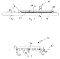
- the sword folder 10 has on both sides of one in the sheet running direction BL extending folding sword 14 arranged above a pair of folding rollers 15 (Fig. 2, 3) several spaced apart Conveyor belts 12, which extend in the sheet running direction BL.
- a pair of folding rollers 15 FIG. 2, 3
- Conveyor belts 12 FIG. 1, 2
- the conveyor belts 12 are shown on the left side of the folding sword 14.
- the ones on the right are identical.
- the folding sword 14 is not shown in FIG. 1. It would be placed before the drawing layer.
- a sheet support plane 30 becomes through the upper runs of the conveyor belts 12 educated.
- a cross strut 24 When viewed downstream in the direction of sheet travel, a cross strut 24 extends transversely to the sheet running direction BL above the conveyor belts 12, on the at a distance mutually arranged stop fingers 16 are provided, which over the Extend sheet support plane 30 downwards.
- a hold-down device 18 is located above each conveyor belt 12 provided, which has a strip 22 extending in the sheet running direction BL, which is arranged parallel to the sheet support plane.
- a strip 22 extending in the sheet running direction BL, which is arranged parallel to the sheet support plane.
- At the bottom of the bar 22 is a plurality of bristle bundles 19_ with bristles 20 of substantially the same Length closely spaced in the direction of the conveyor belt 12 extend and stand at a defined distance from this.
- the bristles 20 are in Sheet travel direction BL inclined so that the angle ⁇ between the longitudinal axis of the Bristles 20 and the folded sheet entering the sheet support plane 30 is preferably 70 ° (Fig. 1).
- Fig. 4 also shows that the bristle bundles 19 in several parallel rows of holes 21 are attached to the underside of the hold-down bars 18, each Hole row plane at an angle ⁇ of 30 to 60 °, preferably 45 °, to the folding sword plane FE runs, with the rows towards the end stop 16 in the direction the folding blade level FE are directed.
- the bristles 20 are at an angle in the row of holes from 60 ° to 80 °, preferably 70 °, inclined to the plane of the arc. This will make a Prevents the sheet from shifting.
- the height of the strips 22 is adjusted by an adjusting device (not shown) adjustable to adjust the pressing force of the bristles 20 on the conveyor belts 12 to be able to. Furthermore, the bristles are angular over the length of the conveyor belt 12 unemployable.
- the arrangement of the bristles 20 extends up to the stop fingers 16. Die Route of the conveyor belt 12, which cover the bristles 20, is designed that creates a sufficient frictional connection between the conveyor belt 12 and sheet which prevents lateral displacement of a sheet to be folded, i.e. that the longitudinal extension of the strips 22 with the bristles 20 the length of the corresponds to the longest folding sheet to be processed.
Landscapes
- Folding Of Thin Sheet-Like Materials, Special Discharging Devices, And Others (AREA)
Abstract
Description
Die Erfindung betrifft ein Schwertfalzwerk nach dem Oberbegriff des Patentanspruchs 1.The invention relates to a sword folding unit according to the preamble of Claim 1.
Ein solches Schwertfalzwerk ist beispielsweise aus der EP 1 176 109 A1 bekannt. Die dabei an den Niederhaltereinrichtungen vorgesehenen Bürsten, die als Gelenk ausgebildet sein können und durch Torsionsfedern in die Reibungseingriffstellung mit der Bogenoberseite vorgespannt werden können, haben in Bogenlaufrichtung eine extrem kurze Länge und dienen lediglich zum Abbremsen des zum Endanschlag durchlaufenden Bogens. Um eine ausreichende Bogenführung zu gewährleisten sind dabei Seitenanschläge vorgesehen.Such a sword folding unit is known for example from EP 1 176 109 A1. The brushes provided on the hold-down devices, which act as a joint can be formed and with torsion springs in the frictional engagement position the top of the sheet can be biased, have a in the sheet running direction extremely short length and only serve to brake the end stop continuous arch. To ensure adequate sheet guidance side stops provided.
Die Verwendung von Borsten an Niederhaltereinrichtungen zum Abbremsen von unter ihnen durchlaufenden Bogen sind beispielsweise auch aus der EP 0 225 576 B1, der US 5,405,127 und der EP 0 161 988 B1 bekannt.The use of bristles on hold-down devices for braking from below sheets passing through them are, for example, also from EP 0 225 576 B1, US 5,405,127 and EP 0 161 988 B1.
Die der Erfindung zugrunde liegende Aufgabe besteht nun darin, das Schwertfalzwerk der gattungsgemäßen Art so auszugestalten, dass eine exakte Bogenführung ohne Seitenanschläge verwirklicht werden kann.The object on which the invention is based is now the sword folding mechanism of the generic type in such a way that an exact sheet guidance can be realized without side stops.
Diese Aufgabe wird durch das Schwertfalzwerk mit den Merkmalen des Patentanspruchs 1 gelöst, wobei die Unteransprüche 2 bis 6 vorteilhafte Ausgestaltungen dieses Schwertfalzwerks beschreiben.This task is performed by the sword folding unit with the characteristics of Patent claim 1 solved, the sub-claims 2 to 6 advantageous embodiments describe this sword folder.
Durch die Anpassung der Längserstreckung der Niederhaltereinrichtungen mit Borsten an die Länge des längsten zu verarbeitenden Falzbogens ist gewährleistet, dass dieser längste Falzbogen beidseitig des Falzschwertes auf seiner ganzen Länge mit den Borsten der Neiderhaltereinrichtungen in Eingriff steht. Dies ist natürlich auch bei Falzbogen der Fall, die kürzer sind als der Falzbogen mit der größten Verarbeitungslänge.By adjusting the longitudinal extent of the hold-down devices with Bristles along the length of the longest folding sheet to be processed are guaranteed that this longest folded sheet on both sides of the folded sword on its whole Length is engaged with the bristles of the envy holder devices. This is Of course, this also applies to folded sheets that are shorter than the folded sheet with the greatest processing length.
Durch die flexiblen Borsten der Niederhaltereinrichtung wird ein Anpressen eines Bogens auf die Transportbänder gewährleistet und somit ein Reibschluss zwischen Transportband und Bogen erzeugt. Darüber hinaus verhindern die Borsten ein Zurückspringen des Bogens nach dem Auftreffen auf die Endanschlageinrichtung. Wenn ein Bogen mit ausreichender Genauigkeit aus einem vorgeschalteten Falzwerk übernommen wird, wird eine ausreichende Bogenzentrierung auch ohne Einsatz von Seitenanschlägen gewährleistet. Die Bogenzentrierung kann durch Einsatz von Perforier-/ Rillwerkzeugen an einer Messerwelle zwischen dem vorgeschalteten Falzwerk und dem Schwertfalzwerk unterstützt werden.The flexible bristles of the hold-down device make it possible to press one Guaranteed sheet on the conveyor belts and thus a frictional connection between Conveyor belt and sheet created. In addition, the bristles prevent one The sheet springs back after hitting the end stop device. If a sheet with sufficient accuracy from an upstream folder is adopted, a sufficient arch centering is also possible without using Side stops guaranteed. The sheet centering can be done by using Perforating / creasing tools on a knife shaft between the upstream Folding unit and the sword folding unit are supported.
Eine winkelgetreue Bogenausrichtung erfolgt über die Endanschlageinrichtung. Die erforderliche Anpresskraft der Borsten kann über die Höhenverstellung der Niederhaltereinrichtung fein eingestellt werden.The end stop device ensures that the bow is aligned at the correct angle. The Required pressing force of the bristles can be adjusted via the height adjustment Hold-down device can be finely adjusted.
Die Niederhaltereinrichtungen können für sich oder zusätzlich zur Höhenverstellung im Winkel zur Bogenlaufrichtung verstellt werden. Zweckmäßigerweise werden sie so verstellt, dass der Andruck der Borsten auf der Seite der Endanschlageinrichtung größer ist als am Einlauf des Falzbogens unter den Niederhaltereinrichtungen.The hold-down devices can be used individually or in addition to the height adjustment can be adjusted at an angle to the direction of sheet travel. It is expedient to do so adjusted that the pressure of the bristles on the side of the end stop device is greater than at the inlet of the folded sheet under the hold-down devices.
Je nach Breite des Schwertfalzwerks werden rechts und links vom Faltschwert vorzugsweise jeweils mindestens zwei Einheiten aus Transportbändern und Niederhaltereinrichtungen mit Borsten eingesetzt.Depending on the width of the sword folding mechanism, right and left of the folding sword preferably at least two units each from conveyor belts and Hold-down devices with bristles are used.
Bevorzugt sind die Borsten so geneigt, dass sie mit dem einlaufenden Falzbogen einen spitzen Winkel zwischen 30° und 80°, vorzugsweise von 70° bilden.The bristles are preferably inclined so that they coincide with the incoming folded sheet form an acute angle between 30 ° and 80 °, preferably 70 °.
Bei einer weiteren bevorzugten Ausführungsform sind die Borsten in Lochreihen an der Unterseite der Niederhaltereinrichtung befestigt, die in einem Winkel von 30° bis 60°, vorzugsweise 45°, zur Falzschwertebene in Richtung der Endanschlageinrichtung geneigt sind, wobei die Borsten in Lochreihenebene in einem Winkel von 60° bis 80°, vorzugsweise 70° zur Bogenebene geneigt sind. In a further preferred embodiment, the bristles are in rows of holes attached to the underside of the hold-down device, which at an angle of 30 ° to 60 °, preferably 45 °, to the folding blade level in the direction of the end stop device are inclined, the bristles in the row of holes at an angle are inclined from 60 ° to 80 °, preferably 70 ° to the plane of the arc.
Als Material für die Borsten wird vorzugsweise Rosshaar oder Kunstfaser, z. B. aus Polyamid verwendet.The material for the bristles is preferably horsehair or synthetic fiber, e.g. B. from Polyamide used.
Ein Ausführungsbeispiel der Erfindung wird nachstehend anhand von Zeichnungen näher erläutert. Es zeigen:
- Fig. 1
- einen schematischen Längsschnitt durch einen Teil des Schwertfalzwerks,
- Fig. 2
- den Schnitt II-II von Fig. 1,
- Fig. 3
- den Schnitt II-II von Fig. 1 in vergrößertem Maßstab,
- Fig. 4
- eine Unteransicht einer Niederhaltereinrichtung.
- Fig. 1
- a schematic longitudinal section through part of the sword folding unit,
- Fig. 2
- the section II-II of Fig. 1,
- Fig. 3
- the section II-II of Fig. 1 on an enlarged scale,
- Fig. 4
- a bottom view of a hold-down device.
Das Schwertfalzwerk 10 weist auf beiden Seiten eines sich in Bogenlaufrichtung BL
erstreckenden und über einem Falzwalzenpaar 15 angeordneten Falzschwertes 14
(Fig. 2, 3) mehrere im Abstand zueinander nebeneinander angeordnete
Transportbänder 12 auf, die sich in Bogenlaufrichtung BL erstrecken. In Fg. 1 und 2
sind nur die Transportbänder 12 auf der linken Seite des Falzschwertes 14 gezeigt.
Die der rechten Seite sind identisch. Das Falzschwert 14 ist in Fig. 1 nicht gezeigt. Es
würde vor der Zeichenebene angeordnet sein.The
Durch die oberen Trums der Transportbänder 12 wird eine Bogenauflageebene 30
gebildet.A
In Bogenlaufrichtung stromabwärts gesehen erstreckt sich eine Querstrebe 24 quer
zur Bogenlaufrichtung BL oberhalb der Transportbänder 12, an der im Abstand
zueinander angeordnete Anschlagfinger 16 vorgesehen sind, die sich über die
Bogenauflageebene 30 hinaus nach unten erstrecken.When viewed downstream in the direction of sheet travel, a
Über jedem Transportband 12 ist jeweils eine Niederhaltereinrichtung 18
vorgesehen, die eine sich in Bogenlaufrichtung BL erstreckende Leiste 22 aufweist,
die parallel zur Bogenauflageebene angeordnet ist. An der Unterseite der Leiste 22
ist eine Vielzahl von Borstenbündeln 19_mit Borsten 20 von im Wesentlichen gleicher
Länge dicht nebeneinander angeordnet, die sich in Richtung des Transportbandes
12 erstrecken und zu diesem in definiertem Abstand stehen. Die Borsten 20 sind in
Bogenlaufrichtung BL so geneigt, dass der Winkel α zwischen der Längsachse der
Borsten 20 und dem auf der Bogenauflageebene 30 einlaufenden Falzbogen
vorzugsweise 70° beträgt (Fig. 1).A hold-
Fig. 4 zeigt außerdem, dass die Borstenbündel 19 in mehreren parallelen Lochreihen
21 an der Unterseite der Niederhalterleisten 18 angebracht sind, wobei jede
Lochreihenebene in einem Winkel γ von 30 bis 60°, vorzugsweise 45°, zu der Falzschwertebene
FE verläuft, wobei die Reihen zum Endanschlag 16 hin in Richtung
der Falzschwertebene FE gerichtet sind.Fig. 4 also shows that the
Wie es in Fig. 3 gezeigt ist, sind die Borsten 20 in Lochreihenebene in einem Winkel
von 60° bis 80°, vorzugsweise 70°, zur Bogenebene geneigt. Hierdurch wird ein
Seitenversatz des Bogens verhindert.As shown in Fig. 3, the
Die Leisten 22 sind durch eine Verstelleinrichtung (nicht gezeigt) in ihrer Höhe
verstellbar, um die Anpresskraft der Borsten 20 auf die Transportbänder 12 einstellen
zu können. Ferner sind die Borsten über die Länge des Transportbandes 12 winklig
anstellbar.The height of the
Die Anordnung der Borsten 20 erstreckt sich bis zu den Anschlagfingern 16. Die
Strecke des Transportbandes 12, die die Borsten 20 abdecken, ist so ausgelegt,
dass ein ausreichender Reibschluss zwischen Transportband 12 und Bogen erzeugt
wird, der eine seitliche Verschiebung eines zu falzenden Bogens verhindert, d.h.,
dass die Längserstreckung der Leisten 22 mit den Borsten 20 der Länge des
längsten zu verarbeitenden Falzbogens entspricht.The arrangement of the
Claims (6)
Applications Claiming Priority (2)
| Application Number | Priority Date | Filing Date | Title |
|---|---|---|---|
| DE20307172U DE20307172U1 (en) | 2003-05-08 | 2003-05-08 | A knife |
| DE20307172U | 2003-05-08 |
Publications (2)
| Publication Number | Publication Date |
|---|---|
| EP1475338A1 true EP1475338A1 (en) | 2004-11-10 |
| EP1475338B1 EP1475338B1 (en) | 2006-07-05 |
Family
ID=27588912
Family Applications (1)
| Application Number | Title | Priority Date | Filing Date |
|---|---|---|---|
| EP20040010097 Expired - Lifetime EP1475338B1 (en) | 2003-05-08 | 2004-04-28 | Knife folding machine |
Country Status (4)
| Country | Link |
|---|---|
| EP (1) | EP1475338B1 (en) |
| JP (1) | JP4791705B2 (en) |
| CN (1) | CN100336708C (en) |
| DE (2) | DE20307172U1 (en) |
Families Citing this family (8)
| Publication number | Priority date | Publication date | Assignee | Title |
|---|---|---|---|---|
| DE102005062843B3 (en) * | 2005-12-27 | 2007-04-19 | Maschinenbau Oppenweiler Binder Gmbh & Co. Kg | Device for folding paper sheets comprises a sheet conveyor and a folding sword with a series of folding rollers arranged one after another in the machine direction |
| DE102006055301A1 (en) * | 2006-11-23 | 2008-05-29 | Heidelberger Druckmaschinen Ag | Sword folding machine with a pocket folder located upstream and method for folding sheets from flat printing material |
| DE102009003235B3 (en) * | 2009-03-27 | 2010-07-08 | Koenig & Bauer Aktiengesellschaft | Method for operating longitudinal folding machine for folding printing product in web-fed rotary printing press, involves correcting declination of length of product by braking element arranged on both sides of folding gap |
| JP5522805B2 (en) | 2010-01-18 | 2014-06-18 | ホリゾン・インターナショナル株式会社 | Knife folding device |
| CN102229386B (en) * | 2011-04-21 | 2012-11-21 | 牡丹江木工机械(厂)有限责任公司 | Transitional bridge for conveying belts |
| DE102012014478A1 (en) | 2012-07-21 | 2013-01-24 | Daimler Ag | Method for starting motor of vehicle e.g. motor vehicle by telematics system, involves determining condition of surroundings of vehicle, to start motor of vehicle |
| CN102849516B (en) * | 2012-08-31 | 2015-02-18 | 苏州一致电子制程有限公司 | Push handle fixing board applicable to folding machine |
| JP7146255B2 (en) * | 2018-10-29 | 2022-10-04 | ホリゾン・インターナショナル株式会社 | knife folding machine |
Citations (5)
| Publication number | Priority date | Publication date | Assignee | Title |
|---|---|---|---|---|
| US4746108A (en) * | 1985-12-04 | 1988-05-24 | Komori Printing Machinery Co., Ltd. | Chopper device for use in a folder |
| US4995858A (en) * | 1989-02-04 | 1991-02-26 | Albert-Frankenthal Ag | Device for halting sheet products |
| EP0639523A1 (en) * | 1993-08-17 | 1995-02-22 | Rockwell Graphic Systems Inc. | Folding apparatus |
| US5992844A (en) * | 1997-12-19 | 1999-11-30 | Marquip, Inc. | Sheet deceleration device using pultruded bristle brushes |
| EP1176109A1 (en) * | 2000-07-28 | 2002-01-30 | MBO MASCHINENBAU OPPENWEILER BINDER GMBH & CO. | Device for folding a sheet by means of a folding blade |
Family Cites Families (6)
| Publication number | Priority date | Publication date | Assignee | Title |
|---|---|---|---|---|
| JPH06104535B2 (en) * | 1986-06-10 | 1994-12-21 | 株式会社小森コーポレーション | Chopper device for folding machine |
| JPH01111663U (en) * | 1988-01-25 | 1989-07-27 | ||
| JP2854067B2 (en) * | 1990-01-31 | 1999-02-03 | ケーニツヒ ウント バウエル―アルバート アクチエンゲゼルシヤフト | Device for stopping signatures |
| JPH0475964A (en) * | 1990-07-13 | 1992-03-10 | Tokyo Kikai Seisakusho Ltd | Chopper folded paper restricting device for rotary press |
| JPH05270731A (en) * | 1992-03-30 | 1993-10-19 | Dainippon Ink & Chem Inc | Folded leaf pressing brush control device of folding machine |
| JPH06234463A (en) * | 1993-02-08 | 1994-08-23 | Mitsubishi Heavy Ind Ltd | Chopper folding device |
-
2003
- 2003-05-08 DE DE20307172U patent/DE20307172U1/en not_active Expired - Lifetime
-
2004
- 2004-04-28 EP EP20040010097 patent/EP1475338B1/en not_active Expired - Lifetime
- 2004-04-28 DE DE200450000902 patent/DE502004000902D1/en not_active Expired - Lifetime
- 2004-05-07 JP JP2004139159A patent/JP4791705B2/en not_active Expired - Lifetime
- 2004-05-08 CN CNB2004100421327A patent/CN100336708C/en not_active Expired - Lifetime
Patent Citations (5)
| Publication number | Priority date | Publication date | Assignee | Title |
|---|---|---|---|---|
| US4746108A (en) * | 1985-12-04 | 1988-05-24 | Komori Printing Machinery Co., Ltd. | Chopper device for use in a folder |
| US4995858A (en) * | 1989-02-04 | 1991-02-26 | Albert-Frankenthal Ag | Device for halting sheet products |
| EP0639523A1 (en) * | 1993-08-17 | 1995-02-22 | Rockwell Graphic Systems Inc. | Folding apparatus |
| US5992844A (en) * | 1997-12-19 | 1999-11-30 | Marquip, Inc. | Sheet deceleration device using pultruded bristle brushes |
| EP1176109A1 (en) * | 2000-07-28 | 2002-01-30 | MBO MASCHINENBAU OPPENWEILER BINDER GMBH & CO. | Device for folding a sheet by means of a folding blade |
Also Published As
| Publication number | Publication date |
|---|---|
| EP1475338B1 (en) | 2006-07-05 |
| DE20307172U1 (en) | 2003-07-10 |
| CN100336708C (en) | 2007-09-12 |
| DE502004000902D1 (en) | 2006-08-17 |
| JP2004331402A (en) | 2004-11-25 |
| CN1572694A (en) | 2005-02-02 |
| JP4791705B2 (en) | 2011-10-12 |
Similar Documents
| Publication | Publication Date | Title |
|---|---|---|
| DE2809226A1 (en) | FOLDING MACHINE FOR PAPER SHEETS | |
| DE4039813A1 (en) | GUIDING DEVICE FOR THE STACKED PILE OF PAPER SHEETS | |
| DD209790A5 (en) | DEVICE FOR TRANSPORTING CONTINUOUS, FLAECHIC PAPER PRODUCTS | |
| DE3244422C2 (en) | ||
| EP1475338B1 (en) | Knife folding machine | |
| DE102007053490A1 (en) | Gatherer/gang stitcher for collating folded sheets to form brochure, has driving elements adjustable between inactive position and active position, and inkjet device fitted to side of gathering section | |
| DE4431488C2 (en) | Sheet guiding in the feeder of a sheet printing machine | |
| EP1803674B1 (en) | Folding machine with fixed folding blade | |
| EP1848847B1 (en) | Top cylinder carrier for drafting systems in spinning machines. | |
| DE1611775B2 (en) | DEVICE FOR SEPARATING RELATED FORM MATERIAL INTO SECTIONS | |
| CH668382A5 (en) | DEVICE FOR CUTTING ONE OR SEVERAL WHOLE OR PARTLY OVERLAYING ARCHES. | |
| DE2546599B2 (en) | Conveyor device for cigarettes with a reservoir | |
| CH634530A5 (en) | DEVICE FOR CONVEYING AND SEPARATING FOLDED PRINTED PRODUCTS. | |
| DE3136793C2 (en) | ||
| EP1504922B1 (en) | Transportation device with thickness measurement of book blocks | |
| AT503214A2 (en) | BELT GUIDE SETUP | |
| DE10060752B4 (en) | Device for continuous folding of flat material | |
| EP1074496B1 (en) | Device for gathering printed matter | |
| DE10033499A1 (en) | Gas- and liquid-permeable conveyor belt is made up of rigid links with apertures in their surface, bearings with central bore allowing links to be connected by cross-bars | |
| DE4332516C2 (en) | Process for merging folded products | |
| EP1568642B1 (en) | Folding pocket with a device for adjusting the gap of the pocket | |
| DE3131041A1 (en) | FOLDING A WORKPIECE FOR CUTTING AND SEWING MACHINES | |
| DE10130209B4 (en) | Method for inserting at least one reading tape in book blocks and apparatus for carrying out the method | |
| DE60115739T2 (en) | Method and device for fraying a sheet-like packaging material | |
| CH670810A5 (en) |
Legal Events
| Date | Code | Title | Description |
|---|---|---|---|
| PUAI | Public reference made under article 153(3) epc to a published international application that has entered the european phase |
Free format text: ORIGINAL CODE: 0009012 |
|
| AK | Designated contracting states |
Kind code of ref document: A1 Designated state(s): AT BE BG CH CY CZ DE DK EE ES FI FR GB GR HU IE IT LI LU MC NL PL PT RO SE SI SK TR |
|
| AX | Request for extension of the european patent |
Extension state: AL HR LT LV MK |
|
| 17P | Request for examination filed |
Effective date: 20050411 |
|
| AKX | Designation fees paid |
Designated state(s): DE FR GB IT |
|
| GRAP | Despatch of communication of intention to grant a patent |
Free format text: ORIGINAL CODE: EPIDOSNIGR1 |
|
| GRAS | Grant fee paid |
Free format text: ORIGINAL CODE: EPIDOSNIGR3 |
|
| GRAA | (expected) grant |
Free format text: ORIGINAL CODE: 0009210 |
|
| AK | Designated contracting states |
Kind code of ref document: B1 Designated state(s): DE FR GB IT |
|
| PG25 | Lapsed in a contracting state [announced via postgrant information from national office to epo] |
Ref country code: IT Free format text: LAPSE BECAUSE OF FAILURE TO SUBMIT A TRANSLATION OF THE DESCRIPTION OR TO PAY THE FEE WITHIN THE PRESCRIBED TIME-LIMIT;WARNING: LAPSES OF ITALIAN PATENTS WITH EFFECTIVE DATE BEFORE 2007 MAY HAVE OCCURRED AT ANY TIME BEFORE 2007. THE CORRECT EFFECTIVE DATE MAY BE DIFFERENT FROM THE ONE RECORDED. Effective date: 20060705 |
|
| REG | Reference to a national code |
Ref country code: GB Ref legal event code: FG4D Free format text: NOT ENGLISH |
|
| REF | Corresponds to: |
Ref document number: 502004000902 Country of ref document: DE Date of ref document: 20060817 Kind code of ref document: P |
|
| GBT | Gb: translation of ep patent filed (gb section 77(6)(a)/1977) |
Effective date: 20061009 |
|
| ET | Fr: translation filed | ||
| PLBE | No opposition filed within time limit |
Free format text: ORIGINAL CODE: 0009261 |
|
| STAA | Information on the status of an ep patent application or granted ep patent |
Free format text: STATUS: NO OPPOSITION FILED WITHIN TIME LIMIT |
|
| 26N | No opposition filed |
Effective date: 20070410 |
|
| PGRI | Patent reinstated in contracting state [announced from national office to epo] |
Ref country code: IT Effective date: 20080601 |
|
| REG | Reference to a national code |
Ref country code: DE Ref legal event code: R082 Ref document number: 502004000902 Country of ref document: DE Representative=s name: KROHER - STROBEL RECHTS- UND PATENTANWAELTE PA, DE |
|
| PGFP | Annual fee paid to national office [announced via postgrant information from national office to epo] |
Ref country code: GB Payment date: 20140422 Year of fee payment: 11 |
|
| PGFP | Annual fee paid to national office [announced via postgrant information from national office to epo] |
Ref country code: IT Payment date: 20140419 Year of fee payment: 11 Ref country code: FR Payment date: 20140424 Year of fee payment: 11 |
|
| GBPC | Gb: european patent ceased through non-payment of renewal fee |
Effective date: 20150428 |
|
| PG25 | Lapsed in a contracting state [announced via postgrant information from national office to epo] |
Ref country code: IT Free format text: LAPSE BECAUSE OF FAILURE TO SUBMIT A TRANSLATION OF THE DESCRIPTION OR TO PAY THE FEE WITHIN THE PRESCRIBED TIME-LIMIT Effective date: 20150428 Ref country code: GB Free format text: LAPSE BECAUSE OF NON-PAYMENT OF DUE FEES Effective date: 20150428 |
|
| REG | Reference to a national code |
Ref country code: FR Ref legal event code: ST Effective date: 20151231 |
|
| PG25 | Lapsed in a contracting state [announced via postgrant information from national office to epo] |
Ref country code: FR Free format text: LAPSE BECAUSE OF NON-PAYMENT OF DUE FEES Effective date: 20150430 |
|
| REG | Reference to a national code |
Ref country code: DE Ref legal event code: R082 Ref document number: 502004000902 Country of ref document: DE Representative=s name: KROHER - STROBEL RECHTS- UND PATENTANWAELTE PA, DE Ref country code: DE Ref legal event code: R081 Ref document number: 502004000902 Country of ref document: DE Owner name: MBO POSTPRESS SOLUTIONS GMBH, DE Free format text: FORMER OWNER: MASCHINENBAU OPPENWEILER BINDER GMBH & CO. KG, 71570 OPPENWEILER, DE Ref country code: DE Ref legal event code: R082 Ref document number: 502004000902 Country of ref document: DE Representative=s name: KROHER STROBEL RECHTS- UND PATENTANWAELTE PART, DE |
|
| PGFP | Annual fee paid to national office [announced via postgrant information from national office to epo] |
Ref country code: DE Payment date: 20230427 Year of fee payment: 20 |
|
| REG | Reference to a national code |
Ref country code: DE Ref legal event code: R071 Ref document number: 502004000902 Country of ref document: DE |