EP0091582B1 - Device for drawing asunder piles of folded products mutually staggered transversely to the direction of transport - Google Patents
Device for drawing asunder piles of folded products mutually staggered transversely to the direction of transport Download PDFInfo
- Publication number
- EP0091582B1 EP0091582B1 EP83102911A EP83102911A EP0091582B1 EP 0091582 B1 EP0091582 B1 EP 0091582B1 EP 83102911 A EP83102911 A EP 83102911A EP 83102911 A EP83102911 A EP 83102911A EP 0091582 B1 EP0091582 B1 EP 0091582B1
- Authority
- EP
- European Patent Office
- Prior art keywords
- belt
- transport
- clamp
- belts
- guide
- Prior art date
- Legal status (The legal status is an assumption and is not a legal conclusion. Google has not performed a legal analysis and makes no representation as to the accuracy of the status listed.)
- Expired
Links
- 230000007246 mechanism Effects 0.000 claims 4
- 230000002596 correlated effect Effects 0.000 claims 2
- 230000005540 biological transmission Effects 0.000 claims 1
- 230000008859 change Effects 0.000 description 3
- 230000000694 effects Effects 0.000 description 2
- 238000012423 maintenance Methods 0.000 description 2
- 230000007257 malfunction Effects 0.000 description 2
- 238000004519 manufacturing process Methods 0.000 description 2
- 230000000717 retained effect Effects 0.000 description 2
- 230000008719 thickening Effects 0.000 description 2
- 238000010276 construction Methods 0.000 description 1
- 230000008878 coupling Effects 0.000 description 1
- 238000010168 coupling process Methods 0.000 description 1
- 238000005859 coupling reaction Methods 0.000 description 1
- 238000011161 development Methods 0.000 description 1
- 230000018109 developmental process Effects 0.000 description 1
- 238000006073 displacement reaction Methods 0.000 description 1
- 238000004806 packaging method and process Methods 0.000 description 1
- 238000005096 rolling process Methods 0.000 description 1
- 238000000926 separation method Methods 0.000 description 1
- 230000007704 transition Effects 0.000 description 1
- 238000011144 upstream manufacturing Methods 0.000 description 1
Images
Classifications
-
- B—PERFORMING OPERATIONS; TRANSPORTING
- B65—CONVEYING; PACKING; STORING; HANDLING THIN OR FILAMENTARY MATERIAL
- B65H—HANDLING THIN OR FILAMENTARY MATERIAL, e.g. SHEETS, WEBS, CABLES
- B65H29/00—Delivering or advancing articles from machines; Advancing articles to or into piles
- B65H29/66—Advancing articles in overlapping streams
- B65H29/6672—Advancing articles in overlapping streams dividing an overlapping stream into two or more streams
-
- B—PERFORMING OPERATIONS; TRANSPORTING
- B65—CONVEYING; PACKING; STORING; HANDLING THIN OR FILAMENTARY MATERIAL
- B65H—HANDLING THIN OR FILAMENTARY MATERIAL, e.g. SHEETS, WEBS, CABLES
- B65H29/00—Delivering or advancing articles from machines; Advancing articles to or into piles
- B65H29/66—Advancing articles in overlapping streams
- B65H29/6609—Advancing articles in overlapping streams forming an overlapping stream
-
- B—PERFORMING OPERATIONS; TRANSPORTING
- B65—CONVEYING; PACKING; STORING; HANDLING THIN OR FILAMENTARY MATERIAL
- B65H—HANDLING THIN OR FILAMENTARY MATERIAL, e.g. SHEETS, WEBS, CABLES
- B65H2301/00—Handling processes for sheets or webs
- B65H2301/40—Type of handling process
- B65H2301/44—Moving, forwarding, guiding material
- B65H2301/444—Stream of articles in shingled formation, overlapping stream
- B65H2301/4447—Stream of articles in shingled formation, overlapping stream multiple streams
- B65H2301/44474—Stream of articles in shingled formation, overlapping stream multiple streams interfolded
-
- B—PERFORMING OPERATIONS; TRANSPORTING
- B65—CONVEYING; PACKING; STORING; HANDLING THIN OR FILAMENTARY MATERIAL
- B65H—HANDLING THIN OR FILAMENTARY MATERIAL, e.g. SHEETS, WEBS, CABLES
- B65H2301/00—Handling processes for sheets or webs
- B65H2301/40—Type of handling process
- B65H2301/44—Moving, forwarding, guiding material
- B65H2301/447—Moving, forwarding, guiding material transferring material between transport devices
- B65H2301/4473—Belts, endless moving elements on which the material is in surface contact
- B65H2301/44732—Belts, endless moving elements on which the material is in surface contact transporting articles in overlapping stream
-
- B—PERFORMING OPERATIONS; TRANSPORTING
- B65—CONVEYING; PACKING; STORING; HANDLING THIN OR FILAMENTARY MATERIAL
- B65H—HANDLING THIN OR FILAMENTARY MATERIAL, e.g. SHEETS, WEBS, CABLES
- B65H2301/00—Handling processes for sheets or webs
- B65H2301/40—Type of handling process
- B65H2301/44—Moving, forwarding, guiding material
- B65H2301/447—Moving, forwarding, guiding material transferring material between transport devices
- B65H2301/44765—Rotary transport devices with compartments
Definitions
- the invention relates to a device for pulling apart sheets which are offset with respect to one another transversely to the transport direction, preferably of folded products transported in the form of a scale track over a transport route, with folded products arranged in the region of a section of the transport route on both sides of the product track, with the free edge of the respective facing offset Sheets which can be brought into engagement and are driven with the same holding device running in the transport direction, at least one of which also has a movement component running transversely to the transport direction.
- a device of this type is known from DE-PS 2 417 614. Since, in devices of this type, two folding products of the same or different thickness can be folded together and possibly trimmed, a second or a double-width folding device is unnecessary.
- the holding devices are designed as gripper rows which are each guided on an endless track and have grippers arranged next to one another, which grasp a respectively assigned sheet package at its free edge formed by the mutual offset and bring it into the desired lateral position.
- the disadvantage here is that the predetermined distance between the grippers requires a precise distance between the successive folding products.
- the grippers have a fixed mutual distance.
- each holding device which also has a movement component running transversely to the transport direction, as a band guide with its front end protruding laterally in relation to the transport direction and having a straight edge strip formed by the facing, offset by the sheet offset of the product web is formed through the clamping gap, which is delimited by mutually opposite, uniformly rotating clamping bands.
- each clamping gap on the side is delimited by at least two clamping bands rolling on one another advantageously results in an elastic, gap-free limitation of this clamping gap over its entire length and thus not only a particularly simple construction but also a particularly high degree of freedom from interference.
- the advantages that can be achieved with the invention can therefore be seen in particular in their simplicity and therefore overall in excellent economy.
- the clamping bands can advantageously be supported by pressure rollers arranged in the area between their deflection devices.
- the opposing pressure rollers of the lower and upper clamping band of a band guide can advantageously be offset from one another in the transport direction in order to ensure high elasticity in the region of the clamping gap. This ensures that thickenings in the area of the product flow can also be absorbed without disruption and readjustment.
- a further advantageous embodiment of the superordinate measures can consist in the fact that at least one clamping band, preferably all clamping bands of each band guide, are designed as toothed belts received on toothed belt wheels. These measures result in a non-slip
- the upper and lower clamping bands of each band guide can advantageously be connected to one another in terms of drive by means of a countershaft arranged in the region of a toothed belt wheel pair.
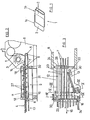
- the folding product 1 shown in FIG. 1 consists of two interlocking sheet packs 1a and 1b, which are laterally offset from one another, so that in the area of each side there is a free edge 2 with which one sheet pack projects above the other.
- the width of the edge 2 corresponds to the lateral offset.
- the two sheet packs 1a and 1b can be grasped and pulled apart, so that two separate folding products result, which can have the same or different number of pages.
- the production of these two folding products can, however, be carried out together in one folding device, the working width of which corresponds only to the width of a product plus the lateral offset.
- the structure and mode of operation of a folder are known per se and therefore do not require any detailed explanation in the present context.
- the folded and possibly trimmed folding products are, as can be seen in FIG. 2, deposited by a paddle wheel 3 in the form of a shingled stream 4 on a delivery belt 5, which consists of carrying belts 7 which are guided around belt rollers 6 and are laterally spaced apart.
- the belt rollers 6 can simply be mounted in the side walls 8 of the folder.
- the delivery belt 5 leading out of the folder forms the first section of a multi-part transport route leading to a further processing device, for example to a packaging device.
- holding devices are provided on both sides of the shingled stream 4, which hold the passing folding products at the respectively assigned free edge 2 and transport them further in the direction of transport and from one another separate, ie pull apart sideways.
- Belt rollers are also provided to accommodate the conveyor belts 7 forming the transport route section 9 and the further transport route sections.
- a common belt roller can be provided in the toothing area of successive transport route sections, on which the carrying belts 7 of successive transport route sections are lined up in an alternating sequence, which automatically results in a drive-related connection of the individual transport route sections.
- At least one upper and one associated lower clamping band 10 and 11 are provided, respectively, web guides 12 and 13, each of which delimit a straight, continuous clamping gap 14, which extends over its entire length and which faces from the respective one , through the relevant edges 2 formed edge strips of the scale web 4 is penetrated.
- the two web guides 12 and 13 can be extended laterally with their front end opposite to the transport direction indicated by the arrow 15.
- the one web guide 12 is arranged parallel to the transport direction and only the other web guide 13 with its front end at a certain angle relative to the transport direction is flared.
- the length of the web guides 12 and 13 and the size of the opening angle are chosen so that a complete separation and a sufficient distance between the separated products are achieved even with the maximum product width.
- the maximum product width corresponds to the working width of the upstream folder minus the width of the smallest required offset. If the product width changes, only the width of the offset is expediently changed, so that no lateral adjustment of the web guides 12 or 13 is necessary.
- the web guides can therefore be arranged stationary. However, it would also be conceivable to provide lateral adjustability. For this it is sufficient if only the web guide 12 parallel to the direction of transport is arranged to be laterally adjustable.
- the clamping bands 10, 11 forming the web guides 12 and 13 are driven by the folder.
- the drive takes place via the conveyor belt 5, which is driven in a manner not shown here.
- the lower clamping belt 10 of the web guide 12 parallel to the transport direction is accommodated on the belt rollers 6 assigned to the adjacent carrying belts 7, of which the belt roller at the rear in the transport direction also belongs to the delivery belt 5 .
- the upper clamping band 11 is received on band wheels 18 arranged above the band rollers 6.
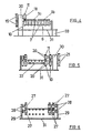
- the drive coupling with the assigned lower clamping band 10 takes place, as can best be seen from FIG. 4, via spur gears 19 arranged on laterally projecting drive stubs 19.
- the clamping bands 10 and 11 of the laterally flared web guide 13 are on in the area between the web rollers 6 Transport route section 9 arranged band wheels 20 which, as shown in FIG. 5, are also drivingly coupled to each other by spur gears 21 placed on laterally projecting drive stubs.
- the torque is introduced via a cardan shaft 22, which is connected to the front belt roller 6 of the delivery belt 5 by means of a countershaft arranged here laterally outside of the web guide 12.
- a toothed belt 23 is provided for this purpose, which is received on a toothed belt pinion 24 on the belt roll side and a toothed belt wheel 25 mounted parallel to the axis thereof.
- the clamping tapes 10 and 11 can be designed as simple tapes similar to the support tapes 7. In order to achieve a smooth running of the clamping bands 10 and 11, they should be designed as toothed belts in the exemplary embodiment shown, which in a simple manner achieves exact synchronism of the clamping bands. This ensures that there is no relative movement of the clamping bands relative to the products detected on the edge, so that they are protected.
- the belt wheels 18 and 20 are designed in this case as toothed belt wheels.
- the belt rollers 6 are provided with the clamping belt 10, which is accommodated thereon and assigned to the web guide 12, toothed belt pinions 26.
- the web guides 12 and 13 can each be formed by aligned individual bands or multiple bands.
- 12 individual belts are provided to form the web guide.
- Double belts are provided to form the web guide 13.
- pressure rollers 27 are provided in the area between the deflection devices assigned to the clamping bands 10 and 11, as can be seen in particular in FIGS. 2 and 6, which support the effective engagement strand of the respectively assigned clamping band, so that over the entire length of the Clamping gap 14 reliable sheet entrainment is guaranteed.
- the pressure rollers 27 assigned to the lower clamping band 10 and the respectively associated upper clamping band 11 are offset with respect to one another in the transport direction, so that a certain elasticity is retained in the region of the clamping gap 14, which thus also copies of stronger material or thickening of the scale flow without damaging the drive means and can record without readjustment, which ensures trouble-free transport.
- the distance between the toothed belt wheels 18 can be adjustable to accomplish any length compensation that may be required. In the exemplary embodiment shown, one or both toothed belt wheels 18 should simply be arranged correspondingly resiliently. When processing shingled streams with a thickness that differs greatly from one another, it may be expedient to arrange at least the upper and / or the lower pressure rollers 27 in an adjustable manner.
- An inlet or outlet gap may result in the area of the belt deflections.
- the pressure rollers 27 are freely rotatably received on side cheeks 28, which in turn are fastened to holders 29 fixed to the housing.
- bearing blocks 30 arranged on a carrier plate 31 are provided.
- the carrier plate 31 is pivotally attached to the folder side walls 8 by means of holders 32 and rests on the floor via supports 33.
- the toothed belt wheel 25 connected to the cardan shaft 22 can simply be found in egg ner projection of the adjacent bearing block 30 may be mounted.
- the holders 29 assigned to the cheeks 28 are also fastened on the carrier plate 31.
- the transport route section 9 adjoining the transport route section 9 having the lateral web guides 12 and 13 is positioned so close with its rear belt roller 6 to the front belt roller 6 of section 9 that there is a smooth transition.
- the side supports 34 of section 17 can be releasably attached to the adjacent bearing blocks 30.
Landscapes
- Engineering & Computer Science (AREA)
- Mechanical Engineering (AREA)
- Delivering By Means Of Belts And Rollers (AREA)
- Folding Of Thin Sheet-Like Materials, Special Discharging Devices, And Others (AREA)
- Separation, Sorting, Adjustment, Or Bending Of Sheets To Be Conveyed (AREA)
Description
Die Erfindung betrifft eine Vorrichtung zum Auseinanderziehen von quer zur Transportrichtung gegeneinander versetzten Bogen von vorzugsweise in Form einer Schuppenbahn über eine Transportstrecke transportierten Falzprodukten mit im Bereich eines Abschnitts der Transportstrecke zu beiden Seiten der Produktbahn angeordneten, mit dem freien Rand der eine ihnen jeweils zugewandte Versetzung aufweisenden Bogen zum Eingriff bringbaren, mit gleicher in Transportrichtung verlaufender Geschwindigkeitskomponente angetriebenen Halteeinrichtungen, von denen zumindest eine auch eine quer zur Transportrichtung verlaufende Bewegungskomponente besitzt.The invention relates to a device for pulling apart sheets which are offset with respect to one another transversely to the transport direction, preferably of folded products transported in the form of a scale track over a transport route, with folded products arranged in the region of a section of the transport route on both sides of the product track, with the free edge of the respective facing offset Sheets which can be brought into engagement and are driven with the same holding device running in the transport direction, at least one of which also has a movement component running transversely to the transport direction.
Eine Vorrichtung dieser Art ist aus der DE-PS 2 417 614 bekannt. Da bei Vorrichtungen dieser Art zwei gleich oder verschieden starke Falzprodukte gemeinsam gefalzt und eventuell beschnitten werden können, wird ein zweiter bzw. ein doppelt breiter Falzapparat entbehrlich. Bei der bekannten Anordnung gemäss DE-PS 2 417 614 sind die Halteeinrichtungen als auf jeweils einer Endlosbahn geführte Greiferreihen mit nebeneinander angeordneten Greifern ausgebildet, die ein jeweils zugeordnetes Bogenpaket an seinem freien durch den gegenseitigen Versatz gebildeten Rand erfassen und in die gewünschte Seitenlage bringen. Nachteilig hierbei ist, dass der fest vorgegebene Abstand der Greifer einen genauen Abstand der aufeinanderfolgenden Falzprodukte bedingt. Die Greifer besitzen einen festen gegenseitigen Abstand. Um sicherzustellen, dass jeder Greifer nur das ihm zugeordnete Bogenpaket ergreift, muss hierbei der Abstand der aufeinanderfolgenden Falzprodukte genauso gross wie der Greiferabstand sein. Wenn dies nicht der Fall ist, kann es vorkommen, dass ein Greifer z.B. mehrere Produkte gleichzeitig erfasst, was zu Störungen führt. Die Erfahrung zeigt jedoch, dass sich der Schuppenabstand von schuppenförmig auf ein Transportband aufgelegten Falzprodukten z.B. aufgrund unterschiedlicher Reibung oder dergleichen ändern kann. Bei Verwendung der Vorrichtung gemäss DE-PS 2 417 614 ist es daher erforderlich, die Falzprodukte genau auszurichten und den Schuppenabstand laufend zu kontrollieren. Die bekannte Anordnung erweist sich daher bereits von dieser Seite her als äusserst aufwendig und dennoch störanfällig. Ausserdem ist davon auszugehen, dass es sich bei den hier verwendeten Greifern um sehr empfindliche und daher ebenfalls störanfällige, einen hohen Wartungsaufwand bedingende Bauelemente handelt. Ganz besonders nachteilig ist hierbei, dass die genannten Greifer auf- und zugesteuert werden müssen, was nicht nur zu einer hohen Lärmerzeugung, sondern auch zu einem verhältnismässig starken Verschleiss führen kann. Ein weiterer, ganz besonderer Nachteil der bekannten Anordnung ist jedoch darin zu sehen, dass bei einer Produktionsänderung mit einer Änderung des Schuppenabstands auch die Greiferabstände geändert werden müssen. Die bekannte Anordnung erweist sich daher nicht nur als aufwendig und störanfällig, sondern auch als nicht variabel genug.A device of this type is known from DE-PS 2 417 614. Since, in devices of this type, two folding products of the same or different thickness can be folded together and possibly trimmed, a second or a double-width folding device is unnecessary. In the known arrangement according to DE-PS 2 417 614, the holding devices are designed as gripper rows which are each guided on an endless track and have grippers arranged next to one another, which grasp a respectively assigned sheet package at its free edge formed by the mutual offset and bring it into the desired lateral position. The disadvantage here is that the predetermined distance between the grippers requires a precise distance between the successive folding products. The grippers have a fixed mutual distance. In order to ensure that each gripper only grips the sheet package assigned to it, the distance between the successive folding products must be as large as the distance between the grippers. If this is not the case, it can happen that a gripper e.g. recorded several products simultaneously, which leads to malfunctions Experience shows, however, that the distance between the scales of folded products placed in a scale on a conveyor belt e.g. may change due to different friction or the like. When using the device according to DE-PS 2 417 614, it is therefore necessary to align the folded products precisely and to continuously control the scale spacing. The known arrangement therefore proves to be extremely complex from this side and is nevertheless prone to failure. In addition, it can be assumed that the grippers used here are very sensitive and therefore also prone to malfunction and require high maintenance. It is particularly disadvantageous here that the grippers mentioned have to be opened and closed, which can lead not only to a high level of noise generation but also to a relatively high level of wear. Another, very particular disadvantage of the known arrangement, however, is the fact that when changing the production with a change in the scale spacing, the gripper distances must also be changed. The known arrangement therefore proves to be not only complex and prone to failure, but also not variable enough.
Hiervon ausgehend ist es daher die Aufgabe der vorliegenden Erfindung, unter Vermeidung der Nachteile der bekannten Anordnungen, eine Vorrichtung eingangs erwähnter Art zu schaffen, die auch bei ungenauem bzw. variablem Schuppenstand ohne entsprechende Nachstellung störungsfrei arbeitet und dennoch vergleichsweise einfach und robust aufgebaut ist und eine hohe Wartungsfreiheit besitzt.Proceeding from this, it is therefore the object of the present invention, while avoiding the disadvantages of the known arrangements, to provide a device of the type mentioned, which works without problems even with inaccurate or variable scale position without corresponding adjustment and is nevertheless comparatively simple and robust and one has a high level of maintenance.
Die Lösung dieser Aufgabe gelingt gemäss der Erfindung in überraschend einfacher Weise dadurch, dass jede auch eine quer zur Transportrichtung verlaufende Bewegungskomponente besitzende Halteeinrichtung als mit ihrem in Transportrichtung vorderen Ende gegenüber der Transportrichtung seitlich ausgestellte Bandführung mit einem geraden, vom zugewandten, durch den Bogenversatz gebildeten Randstreifen der Produktbahn durchsetzbaren Klemmspalt ausgebildet ist, der durch einander gegenüberliegende, gleichförmig umlaufende Klemmbänder begrenzt ist.This object is achieved in a surprisingly simple manner according to the invention in that each holding device which also has a movement component running transversely to the transport direction, as a band guide with its front end protruding laterally in relation to the transport direction and having a straight edge strip formed by the facing, offset by the sheet offset of the product web is formed through the clamping gap, which is delimited by mutually opposite, uniformly rotating clamping bands.
Die in die seitlichen Klemmspalte einlaufenden Produkte werden durch die Klemmbänder geführt und folgen deren Verlauf. Infolge des einfachen Schrägverlaufs zumindest eines Klemmspalts behalten die hierin einlaufenden Produkte ihre Ausrichtung in Laufrichtung bei und werden während des Vorwärtstransports ohne Verdrehung gleichzeitig soweit seitlich transportiert, bis die ineinandersteckenden Bogen vollständig auseinandergezogen sind. Da hierbei nicht jedes Falzprodukt einzeln gegriffen wird, sondern einfach in einen seitlich der Produktbahn verlaufenden, geraden Klemmspalt einläuft, kommt es hierbei auf die Genauigkeit des Produktabstands in vorteilhafter Weise nicht an. Auch bei einem variablen Produktabstand ist eine Umstellung der erfindungsgemässen Anordnung nicht erforderlich, was sich als sehr bedienungsfreundlich erweist. Dadurch, dass jeder seitlich ausgestellte Klemmspalt durch mindestens zwei aufeinander abrollende Klemmbänder begrenzt ist, ergibt sich in vorteilhafter Weise eine elastische, lückenlose Begrenzung dieses Klemmspalts auf seiner ganzen Länge und somit nicht nur eine besonders einfache Bauweise, sondern auch eine besonders hohe Störungsfreiheit. Die mit der Erfindung erzielbaren Vorteile sind demnach insbesondere in ihrer Einfachheit und daher insgesamt in einer ausgezeichneten Wirtschaftlichkeit zu sehen.The products entering the side clamping gaps are led through the clamping bands and follow their course. As a result of the simple inclined course of at least one clamping gap, the products entering here maintain their orientation in the direction of travel and are simultaneously transported laterally without twisting during forward transport until the nested sheets are completely pulled apart. Since here not every folded product is gripped individually, but simply runs into a straight clamping gap running to the side of the product web, the accuracy of the product distance is advantageously not important. Even with a variable product distance, a change in the arrangement according to the invention is not necessary, which has proven to be very user-friendly. The fact that each clamping gap on the side is delimited by at least two clamping bands rolling on one another advantageously results in an elastic, gap-free limitation of this clamping gap over its entire length and thus not only a particularly simple construction but also a particularly high degree of freedom from interference. The advantages that can be achieved with the invention can therefore be seen in particular in their simplicity and therefore overall in excellent economy.
Zur Gewährleistung einer hohen, über der gesamten Klemmspaltlänge praktisch gleichbleibende Klemmwirkung können die Klemmbänder vorteilhaft durch im Bereich zwischen ihren Umlenkeinrichtungen angeordnete Andrückrollen abgestützt sein. Die einander gegenüberliegenden Andrückrollen des unteren und oberen Klemmbands einer Bandführung können dabei vorteilhaft zur Gewährleistung einer hohen Elastizität im Bereich des Klemmspalts in Transportrichtung gegeneinander versetzt sein. Hierdurch ist sichergestellt, dass auch Verdickungen im Bereich des Produktstroms ohne Störung und Nachjustierung aufgenommen werden können.In order to ensure a high clamping effect which remains practically constant over the entire length of the clamping gap, the clamping bands can advantageously be supported by pressure rollers arranged in the area between their deflection devices. The opposing pressure rollers of the lower and upper clamping band of a band guide can advantageously be offset from one another in the transport direction in order to ensure high elasticity in the region of the clamping gap. This ensures that thickenings in the area of the product flow can also be absorbed without disruption and readjustment.
Eine weitere vorteilhafte Ausgestaltung der übergeordneten Massnahmen kann darin bestehen, dass mindestens ein Klemmband, vorzugsweise sämtliche Klemmbänderjede Bandführung als auf Zahnriemenrädern aufgenommene Zahnriemen ausgebildet sind. Diese Massnahmen ergeben einen schlupflosenA further advantageous embodiment of the superordinate measures can consist in the fact that at least one clamping band, preferably all clamping bands of each band guide, are designed as toothed belts received on toothed belt wheels. These measures result in a non-slip
Lauf und ermöglichen daher eine einfache Synchronisierung. Vorteilhaft können dabei die oberen und unteren Klemmbänder jeder Bandführung über ein im Bereich eines Zahnriemenradpaares angeordnetes Vorgelege antriebsmässig miteinander verbunden sein.Run and therefore allow easy synchronization. The upper and lower clamping bands of each band guide can advantageously be connected to one another in terms of drive by means of a countershaft arranged in the region of a toothed belt wheel pair.
Weitere vorteilhafte Ausgestaltungen und zweckmässige Fortbildungen der übergeordneten Massnahmen ergeben sich aus der nachstehenden Beschreibung eines bevorzugten Ausführungsbeispiels anhand der Zeichnung in Verbindung mit den restlichen Unteransprüchen.Further advantageous refinements and expedient further developments of the superordinate measures result from the following description of a preferred exemplary embodiment with reference to the drawing in conjunction with the remaining subclaims.
In der Zeichnung zeigen:
- Fig. 1 eine schematische Ansicht eines Falzprodukts mit quer zur Transportrichtung gegeneinander versetzten Bogen,
- Fig. 2 einen Längsschnitt einer an einen Falzapparat angebauten Trennvorrichtung in schematischer Darstellung,
- Fig. 3 eine Draufsicht auf die Anordnung nach Fig. 2 in schematischer Darstellung,
- Fig. 4 einen Schnitt entlang der Linie IV-IV in Fig. 3,
- Fig. 5 einen Schnitt entlang der Linie V-V in Fig. 3 und
- Fig. 6 einen Schnitt entlang der Linie VI-VI in Fig. 3.
- 1 is a schematic view of a folded product with sheets offset from one another transversely to the transport direction,
- 2 shows a longitudinal section of a separating device attached to a folder in a schematic illustration,
- 3 shows a plan view of the arrangement according to FIG. 2 in a schematic illustration,
- 4 shows a section along the line IV-IV in FIG. 3,
- Fig. 5 shows a section along the line VV in Fig. 3 and
- 6 shows a section along the line VI-VI in FIG. 3rd
Das in Fig. 1 dargestellte Falzprodukt 1 besteht aus zwei ineinandersteckenden Bogenpaketen 1a bzw. 1b, die seitlich gegeneinander versetzt sind, so dass sich im Bereich jeder Seite jeweils ein freier Rand 2 ergibt, mit welchem das eine Bogenpaket das andere überragt. Die Breite des Rands 2 entspricht der seitlichen Versetzung. An diesen seitlichen Rändern 2 können die beiden Bogenpakete 1a bzw. 1b erfasst und auseinander gezogen werden, so dass sich zwei separate Falzprodukte ergeben, die eine gleiche oder verschiedene Seitenzahl aufweisen können. Die Herstellung dieser beiden Falzprodukte kann jedoch gemeinsam in einem Falzapparat erfolgen, dessen Arbeitsbreite lediglich der Breite eines Produkts zuzüglich der seitlichen Versetzung entspricht.The folding product 1 shown in FIG. 1 consists of two
Der Aufbau und die Wirkungsweise eines Falzapparats sind an sich bekannt und bedürfen daher im vorliegenden Zusammenhang keiner eingehenden Erläuterung mehr. Die gefalzten und eventuell beschnittenen Falzprodukte werden, wie Fig. 2 erkennen lässt, durch ein Schaufelrad 3 in Form eines Schuppenstroms 4 auf ein Auslegeband 5 abgelegt, das aus um Bandwalzen 6 herumgeführten, seitlich voneinander distanzierten Tragbändern 7 besteht. Die Bandwalzen 6 können einfach in den Seitenwandungen 8 des Falzapparats gelagert sein. Das aus dem Falzapparat herausführende Auslegeband 5 bildet den ersten Abschnitt einer zu einer Weiterverarbeitungsvorrichtung, etwa zu einer Paketiervorrichtung, führenden, hier mehrteiligen Transportstrecke. Im Bereich des an das Auslegeband 5 sich anschliessenden, durch mit dessen Tragbändern 7 verzahnte Tragbänder 7 gebildeten Abschnitts 9 dieser Transportstrecke sind zu beiden Seiten des Schuppenstroms 4 Halteeinrichtungen vorgesehen, die die vorbeilaufenden Falzprodukte am jeweils zugeordneten freien Rand 2 erfassen und in Transportrichtung weitertransportieren sowie voneinander trennen, d.h. seitlich auseinanderziehen. Zur Aufnahme der den Transport-Streckenabschnitt 9 und der weiteren Transport-Streckenabschnitte bildenden Tragbänder 7 sind ebenfalls Bandwalzen vorgesehen. Im Verzahnungsbereich aufeinanderfolgender Transport-Streckenabschnitte kann jeweils eine gemeinsame Bandwalze vorgesehen sein, auf die die Tragbänder 7 aufeinanderfolgender Transport-Streckenabschnitte in alternierender Reihenfolge aufgereiht sind, wodurch sich automatisch eine antriebsmässige Verbindung der einzelnen Transport-Streckenabschnitte ergibt.The structure and mode of operation of a folder are known per se and therefore do not require any detailed explanation in the present context. The folded and possibly trimmed folding products are, as can be seen in FIG. 2, deposited by a
Zur Bildung der Halteeinrichtungen sind im dargestellten Ausführungsbeispiel aus jeweils mindestens einem oberen und einem zugeordneten unteren Klemmband 10 bzw. 11 bestehende Bahnführungen 12 bzw. 13 vorgesehen, die jeweils einen über ihre ganze Länge sich erstreckenden, gerade durchgehenden Klemmspalt 14 begrenzen, der vom jeweils zugewandten, durch die betreffenden Ränder 2 gebildeten Randstreifen der Schuppenbahn 4 durchsetzt wird. Die beiden Bahnführungen 12 bzw. 13 können mit ihrem vorderen Ende gegenüber der durch den Pfeil 15 angedeuteten Transportrichtung seitlich ausgestellt sein. Im dargestellten Ausführungsbeispiel ist, wie am besten aus Fig. 3 erkennbar ist, die eine Bahnführung 12 parallel zur Transportrichtung angeordnet und lediglich die andere Bahnführung 13 mit ihrem vorderen Ende unter einem gewissen Winkel gegenüber der Transportrichtung seitlich ausgestellt. Die Länge der Bahnführungen 12 bzw. 13 sowie die Grösse des Ausstellwinkels werden so gewählt, dass auch bei maximaler Produktbreite eine vollständige Trennung sowie ein ausreichender Abstand zwischen den getrennten Produkten erreicht werden. Die maximale Produktbreite entspricht hierbei der Arbeitsbreite des vorgeordneten Falzapparats abzüglich der Breite der kleinsten erforderlichen Versetzung. Bei sich ändernder Produktbreite wird zweckmässig lediglich die Breite der Versetzung verändert, so dass keine Seiteneinstellung der Bahnführungen 12 bzw. 13 erforderlich ist. Die Bahnführungen können daher stationär angeordnet sein. Es wäre aber auch denkbar, eine seitliche Verstellbarkeit vorzusehen. Hierzu genügt es, wenn lediglich die transportrichtungsparallele Bahnführung 12 seitlich verstellbar angeordnet ist. Die den Transport-Streckenabschnitt 9 durchlaufenden Produkte, deren auseinanderzuziehende Bogenpakete 1a bzw. 1b mit dem durch die seitliche Versetzung jeweils gebildeten Rand 2 in den jeweils zugeordneten Klemmspalt 14 einlaufen und daher durch die gleichförmig angetriebenen Klemmbänder 10 bzw. 11 infolge der wirksam werdenden Klemmkräfte zuverlässig mitgenommen werden, liegen mit ihren mittleren Bereichen auf den Tragbändern 7 auf, die ebenfalls mit Transportgeschwindigkeit laufen. Es wäre auch denkbar, im Bereich zwischen den beiden seitlichen Bahnführungen 12 bzw. 13 einfach einen stationären, etwa mit erhabenen Stegen oder einem Trittbrettmuster oder dergleichen versehenen Tisch vorzusehen. Es ware auch denkbar, lediglich den infolge der seitlichen Ausstellung der Bahnführung 13 sich ergebenden Zwickel durch ein entsprechendes Zwickelblech auszufachen, wie in Fig. 3 bei 16 angedeutet ist. Eine andere Möglichkeit kann darin bestehen, in diesem Bereich einfach entsprechend verkürzte Tragbänder 7 vorzusehen. Die mit ihrem Rand 2 in den Klemmspalt 14 der transportrichtungsparallelen Bahnführung 12 einlaufenden Bogenpakete werden lediglich in Transportrichtung transportiert und quer hierzu festgehalten. Die mit ihrem Rand 2 in den Klemmspalt 14 der seitlich ausgestellten Bahnführung 13 einlaufenden Bogenpakete werden in Transportrichtung und quer hierzu transportiert. Der Quertransport erfolgt infolge des geradlinigen Verlaufs der Bahnführung 13 ohne Produktdrehung, so dass die transportrichtungsparallele Ausrichtung der Produktseitenkanten bzw. die lotrecht hierzu verlaufende Ausrichtung der Produktvorderkanten erhalten bleibt. Durch den mit Hilfe der Bahnführung 13 bewerkstelligten Seitentransport des hiervon erfassten Bogenpakets erfolgt die Trennung der zunächst ineinandersteckenden Bogenpakete, so dass sich im Anschluss an den Transportstrecken-Abschnitt 9 zwei nebeneinander sich befindende Schuppenströme ergeben. Der an den Abschnitt 9 sich anschliessende Abschnitt 17 der Transportstrecke ist daher gegenüber dem Transportband 5 entsprechend verbreitert. Im Zwickelbereich können, wie weiter oben bereits ausgeführt wurde, ein Zwickelblech 16 und/oder verkürzte Tragbänder vorgesehen sein.To form the holding devices, in the exemplary embodiment shown, at least one upper and one associated
Die die Bahnführungen 12 bzw. 13 bildenden Klemmbänder 10, 11 werden vom Falzapparat her angetrieben. Im dargestellten Ausführungsbeispiel erfolgt der Antrieb über das auf hier nicht näher dargestellte Weise angetriebene Transportband 5. Hierzu ist das untere Klemmband 10 dertransportrichtungsparallelen Bahnführung 12 auf den den benachbarten Tragbändern 7 zugeordneten Bandwalzen 6 aufgenommen, von denen die in Transportrichtung hintere Bandwalze gleichzeitig zum Auslegeband 5 gehört. Das obere Klemmband 11 ist auf oberhalb von den Bandwalzen 6 angeordneten Bandrädern 18 aufgenommen. Die antriebsmässige Kopplung mit dem zugerodneten unteren Klemmband 10 erfolgt, wie am besten aus Fig. 4 erkennbar ist, über auf seitlich auskragenden Antriebsstummeln angeordnete Stirnräder 19. Die Klemmbänder 10 bzw. 11 der seitlich ausgestellten Bahnführung 13 sind auf im Bereich zwischen den Bahnwalzen 6 des Transport-Streckenabschnitts 9 angeordneten Bandrädern 20 aufgenommen, die, wie Fig. 5 zeigt, ebenfalls durch auf seitlich überkragende Antriebsstummel aufgesetzte Stirnräder 21 antriebsmässig miteinander gekoppelt sind. Die Einleitung des Drehmoments erfolgt über eine Kardanwelle 22, die mittels eines hier seitlich ausserhalb der Bahnführung 12 angeordneten Vorgeleges mit der vorderen Bandwalze 6 des Auslegebands 5 antriebsmässig verbunden ist. Im dargestellten Ausführungsbeispiel ist hierzu ein Zahnriemen 23 vorgesehen, der auf einem bandwalzenseitigen Zahnriemenritzel 24 und einem achsparallel hierzu gelagerten Zahnriemenrad 25 aufgenommen ist. Mit Hilfe der Durchmesser von Zahnriemenritzel 24 und Zahnriemenrad 25 lässt sich praktisch jede gewünschte Übersetzung bewerkstelligen. Diese Durchmesser sind so zu wählen, dass die Klemmbänder 10 bzw. 11 der seitlich ausgestellten Bahnführung 13 mit einer Geschwindigkeit angetrieben werden, die sich als Resultierende aus der der Geschwindigkeit der Bahnführung 12 entsprechenden Vorwärtsgeschwindigkeit und der Seitentransportgeschwindigkeit ergibt.The clamping
Die Klemmbänder 10 bzw. 11 können als einfache Bänder ähnlich den Tragbändern 7 ausgebildet sein. Zur Erzielung eines schlupflosen Laufs der Klemmbänder 10 bzw. 11 sollen diese im dargestellten Ausführungsbeispiel als Zahnriemen ausgebildet sein, was auf einfache Weise einen exakten Gleichlauf der Klemmbänder bewerkstelligt. Hierdurch ist sichergestellt, dass Relativbewegungen der Klemmbänder gegenüber den randseitig erfassten Produkten unterbleiben, so dass diese geschont werden. Die Bandräder 18 bzw. 20 sind in diesem Fall als Zahnriemenräder ausgebildet. Die Bandwalzen 6 sind mit dem hierauf aufgenommenen Klemmband 10 der Bahnführung 12 zugeordneten Zahnriemenritzeln 26 versehen. Die Bahn führungen 12 bzw. 13 können jeweils durch miteinander fluchtende Einzelbänder oder Mehrfachbänder gebildet werden. Im dargestellten Ausführungsbeispiel sind zur Bildung der Bahnführung 12 Einzelbänder vorgesehen. Zur Bildung der Bahnführung 13 sind Doppelbänder vorgesehen. Zur Verstärkung der Klemmwirkung sind im Bereich zwischen den den Klemmbändern 10 bzw. 11 zugerordneten Umlenkeinrichtungen, wie insbesondere die Fig. 2 und 6 erkennen lassen, Anpressrollen 27 vorgesehen, welche das wirksame Eingriffstrum des jeweils zugeordneten Klemmbands abstützen, so dass auf der gesamten Länge des Klemmspalts 14 eine zuverlässige Bogenmitnahme gewährleistet ist. Die dem unteren Klemmband 10 und dem jeweils zugehörigen oberen Klemmband 11 zugeordneten Anpressrollen 27 sind in Transportrichtung gegeneinander versetzt, so dass eine gewisse Elastizität im Bereich des Klemmspalts 14 erhalten bleibt, der somit auch Exemplare aus stärkerem Material bzw. Verdickungen des Schuppenstroms ohne Beschädigung der Antriebsmittel und ohne Nachjustierung aufnehmen kann, womit ein störungsfreier Transport gewährleistet ist. Zur Bewerkstelligung eines eventuell erforderlichen Längenausgleichs kann der Abstand zwischen den Zahnriemenrädern 18 einstellbar sein. Im dargestellten Ausführungsbeispiel sollen einfach eines oder beide Zahnriemenräder 18 entsprechend federnd angeordnet sein. Bei der Verarbeitung von Schuppenströmen mit stark voneinander abweichender Dicke kann es zweckmässig sein, zumindest die oberen und/oder die unteren Anpressrollen 27 verstellbar anzuordnen. Im Bereich der Bandumlenkungen kann sich dabei ein Einlauf- bzw. Auslaufspalt ergeben. Es wäre aber auch denkbar, auch die den Klemmbändern zugeordneten Umlenkeinrichtungen entsprechend zu verstellen. Die Anpressrollen 27 sind auf seitlichen Wangen 28 frei drehbar aufgenommen, die ihrerseits an gehäusefesten Haltern 29 befestigt sind.The clamping
Zur Aufnahme der ausserhalb der Falzapparat-Seitenwandungen 8 vorgesehen Bandwalzen 6 und Bandräder 18 bzw. 20 des Transport-Streckenabschnitts 9 sind auf einer Trägerplatte 31 angeordnete Lagerböcke 30 vorgesehen. Die Trägerplatte 31 ist über Halter 32 schwenkbar an den Falzapparat-Seitenwandungen 8 befestigt und liegt über Stützen 33 auf dem Fussboden auf. Das mit der Kardanwelle 22 verbundene Zahnriemenrad 25 kann einfach in einer Auskragung des benachbarten Lagerbocks 30 gelagert sein. Die den Wangen 28 zugeordneten Halter 29 sind ebenfalls auf der Trägerplatte 31 befestigt. Der an den die seitlichen Bahnführungen 12 bzw. 13 aufweisenden Transport-Streckenabschnitt 9 sich anschliessende Transport-Streckenabschnitt 17 ist mit seiner hinteren Bandwalze 6 an die vordere Bandwalze 6 des Abschnitts 9 so nahe angestellt, dass sich ein störungsfreier Übergang ergibt. Die seitlichen Träger 34 des Abschnitts 17 können lösbar an den benachbarten Lagerböcken 30 befestigt werden.To accommodate the
Vorstehend ist zwar ein besonders bevorzugtes Ausführungsbeispiel der Erfindung näher erläutert, ohne dass jedoch hiermit eine Beschränkung verbunden sein soll. So könnten anstelle der Klemmbänder 10 bzw. 11 auch mehrere, in übereinander vorgesehenen Reihen angeordnete, angetriebene Transportrollen Verwendung finden.Although a particularly preferred exemplary embodiment of the invention has been explained in more detail above, this is not intended to imply any limitation. Thus, instead of the clamping
Claims (10)
Applications Claiming Priority (2)
| Application Number | Priority Date | Filing Date | Title |
|---|---|---|---|
| DE19823212350 DE3212350C3 (en) | 1982-04-02 | 1982-04-02 | Device for pulling nested sheets apart. |
| DE3212350 | 1982-04-02 |
Publications (3)
| Publication Number | Publication Date |
|---|---|
| EP0091582A1 EP0091582A1 (en) | 1983-10-19 |
| EP0091582B1 true EP0091582B1 (en) | 1986-02-19 |
| EP0091582B2 EP0091582B2 (en) | 1988-09-21 |
Family
ID=6160110
Family Applications (1)
| Application Number | Title | Priority Date | Filing Date |
|---|---|---|---|
| EP83102911A Expired EP0091582B2 (en) | 1982-04-02 | 1983-03-24 | Device for drawing asunder piles of folded products mutually staggered transversely to the direction of transport |
Country Status (4)
| Country | Link |
|---|---|
| US (1) | US4477066A (en) |
| EP (1) | EP0091582B2 (en) |
| JP (1) | JPS58197145A (en) |
| DE (2) | DE3212350C3 (en) |
Cited By (1)
| Publication number | Priority date | Publication date | Assignee | Title |
|---|---|---|---|---|
| DE10059000A1 (en) * | 2000-11-28 | 2002-06-13 | Koenig & Bauer Ag | Method and device for the transverse displacement of folded products |
Families Citing this family (7)
| Publication number | Priority date | Publication date | Assignee | Title |
|---|---|---|---|---|
| DE3400639A1 (en) * | 1984-01-11 | 1985-07-18 | M.A.N.- Roland Druckmaschinen AG, 6050 Offenbach | DEVICE FOR EXTENDING CROSSING FROM TRANSFECTING DIRECTION TO PRINTED EXTERNAL PARTS |
| AT395302B (en) * | 1989-08-31 | 1992-11-25 | Strohal Gmbh | DEVICE FOR DISTRIBUTING A SHEATH CURRENT FROM EACH OVERHEAD BENEFIT |
| US5882006A (en) * | 1995-10-06 | 1999-03-16 | Baldwin Technology Corporation | Apparatus and method for turning and orienting articles within an article pathway |
| US6158735A (en) * | 1998-02-09 | 2000-12-12 | Heidelberger Druckmaschinen Ag | Apparatus and method for splitting a stream of signatures into a first and second substream of signatures |
| DE10038648A1 (en) * | 2000-08-08 | 2002-02-21 | Markus Gampl | Device for removing fabrics from a shingled stream of such fabrics |
| CH701621A1 (en) * | 2009-08-03 | 2011-02-15 | Ferag Ag | Device and method for storing products. |
| CN102442571B (en) * | 2011-09-26 | 2013-09-11 | 上海汉铁机械有限公司 | Differential order separating device for paperboard stacking machine and order separating method for same |
Family Cites Families (11)
| Publication number | Priority date | Publication date | Assignee | Title |
|---|---|---|---|---|
| FR647597A (en) * | 1927-02-01 | 1928-11-26 | Telephon Apparat Fabrik | Installation of conveyor belts |
| GB1048465A (en) * | 1964-02-21 | 1966-11-16 | Leipziger Buchbinderereimaschi | Improvements in or relating to a device for separating incomplete brochures from thefeeding flow of a gathering and stitching machine |
| CH521911A (en) * | 1970-01-09 | 1972-04-30 | Fehr & Reist Ag | Device for opening folded, bound or stapled, multi-sheet paper products |
| DE2027422C3 (en) * | 1970-06-04 | 1975-07-03 | Willi Kluge | Device for dividing a strip of flaky flat objects, in particular newspapers, lying one on top of the other |
| JPS505700B1 (en) * | 1970-12-25 | 1975-03-06 | ||
| DE2331473A1 (en) * | 1973-06-20 | 1975-01-09 | Roland Offsetmaschf | DEVICE FOR PROMOTING BOWS |
| DE2417614C3 (en) * | 1974-04-10 | 1977-11-03 | Gruner & Jahr | DEVICE FOR DISPLAYING PRODUCTS ON A ROLLER ROTARY PRINTING MACHINE |
| DE2554662A1 (en) * | 1975-12-05 | 1977-06-23 | Koenig & Bauer Ag | PROCESS AND DEVICE FOR IMMEDIATE TRIMMING OF FOLDED SIGNATURES PRODUCED IN ROLLER ROTARY PRINTING MACHINES |
| DD126257B1 (en) * | 1976-06-22 | 1981-01-28 | Guenter Thieme | BAND FILLING DEVICE FOR PUBLISHING AND FORWARDING BOW |
| JPS54144665A (en) * | 1978-04-30 | 1979-11-12 | Masaharu Matsuo | Paper feeder |
| DE2917250A1 (en) * | 1979-04-27 | 1980-10-30 | Gruner & Jahr | Printed matter even overlapping machine - has endless chain with members engaging leading edges of printed sheets on conveyor |
-
1982
- 1982-04-02 DE DE19823212350 patent/DE3212350C3/en not_active Expired
-
1983
- 1983-03-15 US US06/475,577 patent/US4477066A/en not_active Expired - Lifetime
- 1983-03-24 EP EP83102911A patent/EP0091582B2/en not_active Expired
- 1983-03-24 DE DE8383102911T patent/DE3362147D1/en not_active Expired
- 1983-04-01 JP JP58058570A patent/JPS58197145A/en active Pending
Cited By (1)
| Publication number | Priority date | Publication date | Assignee | Title |
|---|---|---|---|---|
| DE10059000A1 (en) * | 2000-11-28 | 2002-06-13 | Koenig & Bauer Ag | Method and device for the transverse displacement of folded products |
Also Published As
| Publication number | Publication date |
|---|---|
| EP0091582B2 (en) | 1988-09-21 |
| DE3212350C2 (en) | 1987-03-26 |
| JPS58197145A (en) | 1983-11-16 |
| US4477066A (en) | 1984-10-16 |
| EP0091582A1 (en) | 1983-10-19 |
| DE3212350C3 (en) | 1988-10-20 |
| DE3362147D1 (en) | 1986-03-27 |
| DE3212350A1 (en) | 1983-10-13 |
Similar Documents
| Publication | Publication Date | Title |
|---|---|---|
| AT397370B (en) | DEVICE FOR COLLECTING FOLDED PRINTED SHEETS | |
| EP2199240B1 (en) | Device for separating parts | |
| DE2823247C2 (en) | Device for deflecting a product flow consisting of curved products | |
| EP0498068A1 (en) | Folder, in which the folded articles are transported using transportation means ,idlers and conveyors | |
| DE1761688B2 (en) | Transport device for flat structures occurring in a scale formation | |
| DE2814383C3 (en) | Device for the directed depositing of individually conveyed flexible foils o. The like. | |
| DE69618520T2 (en) | Deflection device for transporting products, in particular graphic products or publishing products | |
| EP2415700A2 (en) | Device for aligning a flat product | |
| DE3315490A1 (en) | METHOD AND DEVICE FOR STACKING PRINTED SHEETS OR THE LIKE | |
| DE3108044C2 (en) | Device for handling sheets of material | |
| EP0091582B1 (en) | Device for drawing asunder piles of folded products mutually staggered transversely to the direction of transport | |
| CH687245A5 (en) | Means for conveying and separating folded printed products. | |
| DE2917250A1 (en) | Printed matter even overlapping machine - has endless chain with members engaging leading edges of printed sheets on conveyor | |
| DE3119016C2 (en) | ||
| DE2848817C2 (en) | Conveyor device for conveying rod-shaped objects in the tobacco processing industry | |
| DE102010031668B4 (en) | Falt - plant for corrugated webs | |
| EP0625121A1 (en) | Device for transferring an overlapping article stream of printed products | |
| EP0308688B1 (en) | Feeding device for a stack of sheets along a curved path | |
| EP0078519B1 (en) | Loosening device for an overlapping formation of printed products | |
| EP1505026B1 (en) | Device for centering of a shingled stream | |
| DE2903771A1 (en) | Paper sheet handling vacuum braking equipment - has first suction holes connected to transverse passage divided by slide on belt | |
| EP0326518B1 (en) | Conveying device comprising belts for forwarding a stream of flat products | |
| CH631410A5 (en) | Device for homogenising an imbricated stream formed from flat products, in particular printed products | |
| EP1237805B1 (en) | Device for deviating an overlapping stream on a roller table | |
| CH646114A5 (en) | DEVICE FOR SEPARATING A STACK OF FOLDED OR BINDED, MULTI-LEAF PRINTED PRODUCTS. |
Legal Events
| Date | Code | Title | Description |
|---|---|---|---|
| PUAI | Public reference made under article 153(3) epc to a published international application that has entered the european phase |
Free format text: ORIGINAL CODE: 0009012 |
|
| AK | Designated contracting states |
Designated state(s): CH DE FR GB IT LI SE |
|
| 17P | Request for examination filed |
Effective date: 19830825 |
|
| GRAA | (expected) grant |
Free format text: ORIGINAL CODE: 0009210 |
|
| AK | Designated contracting states |
Designated state(s): CH DE FR GB IT LI SE |
|
| REF | Corresponds to: |
Ref document number: 3362147 Country of ref document: DE Date of ref document: 19860327 |
|
| ET | Fr: translation filed | ||
| ITF | It: translation for a ep patent filed | ||
| PLBI | Opposition filed |
Free format text: ORIGINAL CODE: 0009260 |
|
| 26 | Opposition filed |
Opponent name: M.A.N.- ROLAND DRUCKMASCHINEN AKTIENGESELLSCHAFT, Effective date: 19861105 |
|
| PUAH | Patent maintained in amended form |
Free format text: ORIGINAL CODE: 0009272 |
|
| STAA | Information on the status of an ep patent application or granted ep patent |
Free format text: STATUS: PATENT MAINTAINED AS AMENDED |
|
| 27A | Patent maintained in amended form |
Effective date: 19880921 |
|
| AK | Designated contracting states |
Kind code of ref document: B2 Designated state(s): CH DE FR GB IT LI SE |
|
| ET3 | Fr: translation filed ** decision concerning opposition | ||
| ITTA | It: last paid annual fee | ||
| EAL | Se: european patent in force in sweden |
Ref document number: 83102911.1 |
|
| REG | Reference to a national code |
Ref country code: GB Ref legal event code: IF02 |
|
| PGFP | Annual fee paid to national office [announced via postgrant information from national office to epo] |
Ref country code: GB Payment date: 20020227 Year of fee payment: 20 |
|
| PGFP | Annual fee paid to national office [announced via postgrant information from national office to epo] |
Ref country code: FR Payment date: 20020322 Year of fee payment: 20 |
|
| PGFP | Annual fee paid to national office [announced via postgrant information from national office to epo] |
Ref country code: SE Payment date: 20020402 Year of fee payment: 20 |
|
| PGFP | Annual fee paid to national office [announced via postgrant information from national office to epo] |
Ref country code: DE Payment date: 20020403 Year of fee payment: 20 |
|
| PGFP | Annual fee paid to national office [announced via postgrant information from national office to epo] |
Ref country code: CH Payment date: 20020405 Year of fee payment: 20 |
|
| PG25 | Lapsed in a contracting state [announced via postgrant information from national office to epo] |
Ref country code: LI Free format text: LAPSE BECAUSE OF EXPIRATION OF PROTECTION Effective date: 20030323 Ref country code: GB Free format text: LAPSE BECAUSE OF EXPIRATION OF PROTECTION Effective date: 20030323 Ref country code: CH Free format text: LAPSE BECAUSE OF EXPIRATION OF PROTECTION Effective date: 20030323 |
|
| REG | Reference to a national code |
Ref country code: GB Ref legal event code: PE20 |
|
| REG | Reference to a national code |
Ref country code: CH Ref legal event code: PL |
|
| EUG | Se: european patent has lapsed |