EP1176047A1 - Device for guiding and anchoring removable vehicle seats - Google Patents
Device for guiding and anchoring removable vehicle seats Download PDFInfo
- Publication number
- EP1176047A1 EP1176047A1 EP01420158A EP01420158A EP1176047A1 EP 1176047 A1 EP1176047 A1 EP 1176047A1 EP 01420158 A EP01420158 A EP 01420158A EP 01420158 A EP01420158 A EP 01420158A EP 1176047 A1 EP1176047 A1 EP 1176047A1
- Authority
- EP
- European Patent Office
- Prior art keywords
- slide
- flange
- axis
- hook
- transverse
- Prior art date
- Legal status (The legal status is an assumption and is not a legal conclusion. Google has not performed a legal analysis and makes no representation as to the accuracy of the status listed.)
- Granted
Links
Images


Classifications
-
- B—PERFORMING OPERATIONS; TRANSPORTING
- B60—VEHICLES IN GENERAL
- B60N—SEATS SPECIALLY ADAPTED FOR VEHICLES; VEHICLE PASSENGER ACCOMMODATION NOT OTHERWISE PROVIDED FOR
- B60N2/00—Seats specially adapted for vehicles; Arrangement or mounting of seats in vehicles
- B60N2/02—Seats specially adapted for vehicles; Arrangement or mounting of seats in vehicles the seat or part thereof being movable, e.g. adjustable
- B60N2/04—Seats specially adapted for vehicles; Arrangement or mounting of seats in vehicles the seat or part thereof being movable, e.g. adjustable the whole seat being movable
- B60N2/06—Seats specially adapted for vehicles; Arrangement or mounting of seats in vehicles the seat or part thereof being movable, e.g. adjustable the whole seat being movable slidable
- B60N2/08—Seats specially adapted for vehicles; Arrangement or mounting of seats in vehicles the seat or part thereof being movable, e.g. adjustable the whole seat being movable slidable characterised by the locking device
- B60N2/0831—Movement of the latch
- B60N2/0837—Movement of the latch pivoting
- B60N2/0843—Movement of the latch pivoting about a longitudinal axis
-
- B—PERFORMING OPERATIONS; TRANSPORTING
- B60—VEHICLES IN GENERAL
- B60N—SEATS SPECIALLY ADAPTED FOR VEHICLES; VEHICLE PASSENGER ACCOMMODATION NOT OTHERWISE PROVIDED FOR
- B60N2/00—Seats specially adapted for vehicles; Arrangement or mounting of seats in vehicles
- B60N2/005—Arrangement or mounting of seats in vehicles, e.g. dismountable auxiliary seats
- B60N2/015—Attaching seats directly to vehicle chassis
- B60N2/01508—Attaching seats directly to vehicle chassis using quick release attachments
- B60N2/01516—Attaching seats directly to vehicle chassis using quick release attachments with locking mechanisms
- B60N2/01525—Attaching seats directly to vehicle chassis using quick release attachments with locking mechanisms with locking elements expanding inside or under the vehicle floor or rail
- B60N2/01541—Attaching seats directly to vehicle chassis using quick release attachments with locking mechanisms with locking elements expanding inside or under the vehicle floor or rail using moving hooks
-
- B—PERFORMING OPERATIONS; TRANSPORTING
- B60—VEHICLES IN GENERAL
- B60N—SEATS SPECIALLY ADAPTED FOR VEHICLES; VEHICLE PASSENGER ACCOMMODATION NOT OTHERWISE PROVIDED FOR
- B60N2/00—Seats specially adapted for vehicles; Arrangement or mounting of seats in vehicles
- B60N2/005—Arrangement or mounting of seats in vehicles, e.g. dismountable auxiliary seats
- B60N2/015—Attaching seats directly to vehicle chassis
- B60N2/01508—Attaching seats directly to vehicle chassis using quick release attachments
- B60N2/01591—Attaching seats directly to vehicle chassis using quick release attachments with wheels coupled to the seat
-
- B—PERFORMING OPERATIONS; TRANSPORTING
- B60—VEHICLES IN GENERAL
- B60N—SEATS SPECIALLY ADAPTED FOR VEHICLES; VEHICLE PASSENGER ACCOMMODATION NOT OTHERWISE PROVIDED FOR
- B60N2/00—Seats specially adapted for vehicles; Arrangement or mounting of seats in vehicles
- B60N2/02—Seats specially adapted for vehicles; Arrangement or mounting of seats in vehicles the seat or part thereof being movable, e.g. adjustable
- B60N2/04—Seats specially adapted for vehicles; Arrangement or mounting of seats in vehicles the seat or part thereof being movable, e.g. adjustable the whole seat being movable
- B60N2/06—Seats specially adapted for vehicles; Arrangement or mounting of seats in vehicles the seat or part thereof being movable, e.g. adjustable the whole seat being movable slidable
- B60N2/07—Slide construction
- B60N2/0702—Slide construction characterised by its cross-section
- B60N2/0705—Slide construction characterised by its cross-section omega-shaped
-
- B—PERFORMING OPERATIONS; TRANSPORTING
- B60—VEHICLES IN GENERAL
- B60N—SEATS SPECIALLY ADAPTED FOR VEHICLES; VEHICLE PASSENGER ACCOMMODATION NOT OTHERWISE PROVIDED FOR
- B60N2/00—Seats specially adapted for vehicles; Arrangement or mounting of seats in vehicles
- B60N2/02—Seats specially adapted for vehicles; Arrangement or mounting of seats in vehicles the seat or part thereof being movable, e.g. adjustable
- B60N2/04—Seats specially adapted for vehicles; Arrangement or mounting of seats in vehicles the seat or part thereof being movable, e.g. adjustable the whole seat being movable
- B60N2/06—Seats specially adapted for vehicles; Arrangement or mounting of seats in vehicles the seat or part thereof being movable, e.g. adjustable the whole seat being movable slidable
- B60N2/07—Slide construction
- B60N2/0702—Slide construction characterised by its cross-section
- B60N2/0707—J-shaped
-
- B—PERFORMING OPERATIONS; TRANSPORTING
- B60—VEHICLES IN GENERAL
- B60N—SEATS SPECIALLY ADAPTED FOR VEHICLES; VEHICLE PASSENGER ACCOMMODATION NOT OTHERWISE PROVIDED FOR
- B60N2/00—Seats specially adapted for vehicles; Arrangement or mounting of seats in vehicles
- B60N2/02—Seats specially adapted for vehicles; Arrangement or mounting of seats in vehicles the seat or part thereof being movable, e.g. adjustable
- B60N2/04—Seats specially adapted for vehicles; Arrangement or mounting of seats in vehicles the seat or part thereof being movable, e.g. adjustable the whole seat being movable
- B60N2/06—Seats specially adapted for vehicles; Arrangement or mounting of seats in vehicles the seat or part thereof being movable, e.g. adjustable the whole seat being movable slidable
- B60N2/07—Slide construction
- B60N2/0702—Slide construction characterised by its cross-section
- B60N2/0715—C or U-shaped
-
- B—PERFORMING OPERATIONS; TRANSPORTING
- B60—VEHICLES IN GENERAL
- B60N—SEATS SPECIALLY ADAPTED FOR VEHICLES; VEHICLE PASSENGER ACCOMMODATION NOT OTHERWISE PROVIDED FOR
- B60N2/00—Seats specially adapted for vehicles; Arrangement or mounting of seats in vehicles
- B60N2/02—Seats specially adapted for vehicles; Arrangement or mounting of seats in vehicles the seat or part thereof being movable, e.g. adjustable
- B60N2/04—Seats specially adapted for vehicles; Arrangement or mounting of seats in vehicles the seat or part thereof being movable, e.g. adjustable the whole seat being movable
- B60N2/06—Seats specially adapted for vehicles; Arrangement or mounting of seats in vehicles the seat or part thereof being movable, e.g. adjustable the whole seat being movable slidable
- B60N2/07—Slide construction
- B60N2/0702—Slide construction characterised by its cross-section
- B60N2/072—Complex cross-section, e.g. obtained by extrusion
-
- B—PERFORMING OPERATIONS; TRANSPORTING
- B60—VEHICLES IN GENERAL
- B60N—SEATS SPECIALLY ADAPTED FOR VEHICLES; VEHICLE PASSENGER ACCOMMODATION NOT OTHERWISE PROVIDED FOR
- B60N2/00—Seats specially adapted for vehicles; Arrangement or mounting of seats in vehicles
- B60N2/02—Seats specially adapted for vehicles; Arrangement or mounting of seats in vehicles the seat or part thereof being movable, e.g. adjustable
- B60N2/04—Seats specially adapted for vehicles; Arrangement or mounting of seats in vehicles the seat or part thereof being movable, e.g. adjustable the whole seat being movable
- B60N2/06—Seats specially adapted for vehicles; Arrangement or mounting of seats in vehicles the seat or part thereof being movable, e.g. adjustable the whole seat being movable slidable
- B60N2/08—Seats specially adapted for vehicles; Arrangement or mounting of seats in vehicles the seat or part thereof being movable, e.g. adjustable the whole seat being movable slidable characterised by the locking device
- B60N2/0812—Location of the latch
- B60N2/0818—Location of the latch inside the rail
Definitions
- the invention relates to the seats of motor vehicles and relates more particularly to removable seats comprising, on the one hand, anchoring means on longitudinal runners fixed to the floor of the vehicle and, on the other hand, means for adjusting their position longitudinal with locking in the chosen position.
- the seat structure is integral with a base formed by two subsets, respectively right and left, comprising, each, means of positioning relative to the slide corresponding, guide means in transverse translation and longitudinal with respect to the slide, locking means on the slide, such as articulated bolts or latches cooperating with means complementary to the slide, such as returns, notches or notches.
- deformations of the floor can alter the relative positions of two initially parallel slides, by giving a "V" shape in plan over, and / or an inclination different from the floor plan, i.e. generate new conditions altering the sliding and even the replacement during seat positioning.
- the object of the present invention is to remedy this by providing a guide and anchoring device for a removable seat adapting to possible deformations and positioning faults of the runners fixed to the floor and eliminating any risk of jamming and all locking fault on the slides, for all positions that can be occupied by a seat.
- This device applies to the seat in which the base is composed of two side flanges each carrying means of positioning relative to the corresponding slide, means of guiding in translation, respectively, transverse and longitudinal, by relative to these slides, and locking means on the slide that can be brought into the unlocked position by control means.
- one of the flanges of the base directly carries the positioning means, the means of guide, and the locking means, while, in the other flange, says catch-up flange, these same means are carried by one or two carriages anchor mounted floating in transverse translation relative to the flange and over a stroke greater than the maximum value of manufacturing tolerances and fitting the corresponding slide, the single carriage or one of these trolleys being connected to this flange by a single transverse axis with the possibility of pivot in the vertical plane to follow the vertical level variations of the face of the slide on which it is supported.
- the removable seat is perfectly guided in longitudinal translation by its guide flange, but can, by mounting respectively floating and floating-pivoting carts of its flange catching up, adapting to variations in the positioning of the slides, without this influences its locking means with respect to these slides.
- the locking means carried by the guide flange and those carried by the floating carriages of the take-up flange consist of latches pivoting, each lock being articulated around an axis parallel to the axis longitudinal of the slide and provided with a lower end, in the form of hook, penetrating into the gap between the wings of the slide and cooperating with one of the notches in these wings.
- the general resistance of the slide is much less affected only when these notches are made in its upper returns, and said notches can be distributed with a smaller step by increasing the number of locked longitudinal positions that can be given to the seat.
- each of the swivel locks is provided, in addition to this hook, with a latch retainer capable of coming under the internal return of the slide secured to the wing carrying the notch with which the hook cooperates.
- the locking means In the event of an impact during the longitudinal adjustment of the position of the seat, the locking means, although in the unlocked position, continue to participate in the restraint of the seat in the slides.
- the floating carriage linked in rotation and longitudinal translation at the take-up flange, carries an axis transverse cylindrical with an extreme cylindrical bearing surface on which is free rotationally mounted caster capable of rolling on the slide, while the floating and articulated carriage, carries two transverse axes each provided with a extreme cylindrical seat on which a caster is mounted to rotate freely able to roll on the slide, the cylindrical bearings of the three axes transverse receiving the rollers being offset from the axis geometric of the axis, so that the partial pivoting of each axis, then its locking, allow to adjust the vertical position of the corresponding wheel compared to the flange, therefore to the seat.
- Eccentric spans allow mounting, and if necessary workshop after operation, to modify the vertical position of the axes of rotation of the rollers to adjust the vertical clearance between the latches and hooks and the underside of the internal return of the wings of the slide, and limit the play of travel at the top of the backrest.
- the rollers equipping at least the carriage of the take-up flange are part of a series of rollers having the same bore diameter, but differentiated by their outside diameter ranging increasing by a value at most equal to that of the eccentricity of the span cylindrical receiving them.
- each slide has, in cross section, the general shape of a "U"
- the two vertical wings 7a, 7b are vertical and are provided with their upper ends, on the one hand, of an internal return respectively 8a, 8b, on the other hand, of an external return 9a, 9b, and moreover, of a flat face upper 10a, 10b, forming a raceway, but can also form sliding path.
- Figures 2 to 4 show that each of the flanges has, in side view, the general shape of a stick, i.e. has a point 3a, 4a facing forwards, and a tip 3b, 4b facing backwards, separated by a concave central part and comprises, in each of its points, a respectively front 12 and rear 13 bore for, respectively, an axis of connection with the seat structure, and the joint 11 of the back structure 14.
- Each flange is in the form of a box open inwards. The opening of that 3 is closed by a closing plate 15 comprising stiffening ribs. This sheet is linked to the flange 3 by means of dismountable connection, such as screws, materialized by dashed lines 16 (FIG. 2).
- lever 26 receives the support of a radial lug 28, wedged on a pin 29 of a control bar 30 extending under the seat 2.
- This pin is freely mounted in rotation in the bore 32 of the flange, visible in FIG. 5.
- the flange 3 carries two bearings, respectively before 33 and rear 34 receiving, as shown in Figure 2, an axis respectively 35 and 36 the end of which forms a guide surface for a roller, respectively 37, 38.
- These two rollers come to bear on the raceways of the slide corresponding, namely on the raceway 10a for the roller 38, and on the raceway 10b of the same slide for the roller 37.
- the positioning means in the take-up flange 4 the positioning means, the means of guide in longitudinal translation and the locking means are worn by two carriages, respectively, front 40 and rear 41.
- the carriage posterior 41 comprises a body 42 having, in cross section, the general shape of a "U" whose core 42a is traversed longitudinally by cylindrical bores, 43 and 44 respectively, transversely by two cylindrical bores 45 and vertically by two through housings 46, 47.
- the two wings 42b are each traversed by a transverse bore 48 and each have an internal longitudinal groove 49 facing towards the groove of the other wing.
- the housing 46 contains a lock 120, identical to the lock 20 of the flange 3. This lock is articulated around an axis 50 (FIG. 11), disposed in the longitudinal bore 44.
- each of these hooks is intended to enter one of the notches 53 provided, as shown Figure 2, in each of the wings 7a, 7b of the corresponding slide.
- These hooks are associated with an upper step 54, forming a retaining bolt. This bolt is suitable, in the event of an impact, to come to bear under the internal return corresponding 8a or 8b of the slide to retain the base and the seat.
- the lock 120 is secured to a finger radial 55, projecting upwards.
- the housing 47 of the carriage body 42 contains a hook retainer 122, identical in shape to the hook 22 of the guide flange 3. As shown in Figure 13, this hook is articulated on an axis 56, arranged in the bore 43 of the body. At its lower part, it has a step 57 forming hook and fit, like the redan 54 of the lock, to come below the return internal 8a, 8b of the corresponding slide. At its upper part, it is provided a radial finger 58, projecting upwards.
- the bores 45 of the body are intended to receive two transverse axes 59 serving as pivots for two castors 60.
- each axis 59 rotates the corresponding wheel 60 by a cylindrical surface 62 which is offset by a value e with respect to its geometric axis.
- the axis 59 is equipped with a flat 63 making it possible to identify the angular position of this axis, therefore of the eccentric bearing, and consequently, to adjust the position of the axis of rotation of the caster in relation to the carriage.
- the slot 59a, formed in the head 59b of the axis, also participates in locating the adjustment position of the caster.
- the axis 59 is locked in position, for example, by a nut 64.
- the bores 48 formed in the wings 42b of the carriage body serve as housings for bearings 66 for a through axis 65.
- the ends of this axis 65 are carried by bores 67 provided, one in the lower part of the flange 4 and the other in a cheek 68 arranged parallel to the flange and connected to it by a wall 69.
- the flange, the cheek and the wall form an inverted “U” cap containing the carriages.
- FIG. 12 clearly shows that the interval I between the flange 4 and its wall 68 is greater than the width L of the carriage 41, so that provided, on each side of the carriage, Ja, Jb games, allowing it to move transversely, giving it its floating character.
- a blade spring folded into a “V” 71 is linked by its branch 71a to the cheek 68 and takes support, by its branch 71b, on the carriage 41 to return it to a position substantially median, facilitating its engagement in the slide in the seat installation phase.
- the carriage 41 is equipped with a positioning means which, in the embodiment shown, is constituted by a cap made of material plastic 70, forming a kind of protective casing for the pivoting elements of the carriage which pass through it through suitable openings, but it is evident that these positioning means can have any other shape and, by example, be constituted by a plastic plate having the same cross section as the cap, but attached to the carriage.
- a positioning means which, in the embodiment shown, is constituted by a cap made of material plastic 70, forming a kind of protective casing for the pivoting elements of the carriage which pass through it through suitable openings, but it is evident that these positioning means can have any other shape and, by example, be constituted by a plastic plate having the same cross section as the cap, but attached to the carriage.
- the carriage 40 comprises a body 142 having the same cross section as the body 42 of the carriage 41 and whose core 142a is crossed by two longitudinal bores 143, 144 and by a housing vertical through 147 for a retaining hook 122.
- the core 142a is also crossed by a transverse bore for an axis 59 receiving a caster 60.
- the two wings 142b of the body are crossed by transverse bores aligned two by two and each receiving a bearing 66.
- in these bearings are mounted two axes transverse 73. Each axis is arranged, by its ends, in bores 74 formed in the flange 4 and in his cheek 68. These two axes form slides on which the carriage 40 can slide transversely to adapt to the differences in transverse position of the slide relative to the seat or vice versa.
- a spring leaf 75 ensures the same function as the blade 71 of the other carriage 41.
- This carriage 40 also has longitudinal grooves 149, made in its wings and facing each other.
- the latch 120 and the retaining fingers 122 of the take-up flange 4 have a pivot which is controlled by a slide 123, arranged above of them.
- this slide has, in its core, a light 76 and two lights 77.
- the slide is provided at its ends with rollers 78 circulating in the grooves 49 and 149 formed in the wings of the two carriages 40, 41.
- the lights 76, 77 are crossed, each by one of the fingers 55, 58, respectively of the latch and retaining hooks, as shown in Figures 8, 11 and 13.
- the edges of these lights form ramps which, when moving the slide, can come into contact with the corresponding finger, to move it transversely and cause the bolt or hook to pivot corresponding.
- Figure 7 shows that the light 76 for the latch 120 is inclined transversely over its entire length, relative to the axis longitudinal of the slide 123 and has substantially straight edges, while the lights 77 for the hooks 122 are each composed of a longitudinal section 77a and an inclined section 77b.
- Each section longitudinal 77a has a length at least equal to the displacement stroke longitudinal that the slide 123 must perform to bring the lock of its locking position to its unlocking position.
- the slide is secured to a finger hook 81 projecting upwards and on which one of the ends of a tension spring 79, hooked by its other end to a fixed point of the flange and, for example, to an axis 73, as shown in FIG. 8.
- the slide 123 is equipped with a heel 80, able to cooperate with a wedging bar 82 forming part of a feeler presence of the slide.
- this probe consists of a bent lever 83, pivotally mounted on a transverse axis 84 swirling in the flange 4 and its cheek 68.
- This lever carries the bar 82, at the end of its branch substantially horizontal, while the end of its substantially vertical branch is fitted with a caster 85.
- the slide is returned by the spring 79 until the heel 80 abuts on the bar 82, thus ensuring immobilization in the position of extraction of the lock 120 and hooks 122.
- This facilitates the extraction of the seat relative to the slide and subsequently the replacement of the latches and hooks in the slide, while avoiding forming, on the base of the seat, protrusions that can catch other elements.
- FIG. 5 shows that the slide 23 of the guide flange 3 is sliding mounted on cylindrical slides 86 and 87 extending between transverse wings 3c of the flange, and that the return of the slide is ensured by the spring 24 which is arranged around the slide 87.
- the slide comprises also lights 76, 77 which control the tilting of the lock 20 and retaining hooks 22 cooperating with the fingers of these elements.
- the locking means of the slide 23, in its position holding the latch 20 and the hooks 22 in the extraction position, are produced differently, as shown in more detail in Figure 15.
- the means of probing, coming into contact with the slide when the seat is brought to these consist of a piston 88, slidably mounted in a bore vertical shouldered 89, formed in a protrusion 90 of the flange 3.
- the rod 88a of the piston 88 is linked, for example by a transverse pin 92, to a transverse finger 93 extending above the path of the slide 23.
- a spring 91 interposed between the piston 88 and the bottom of the housing 89, urges permanently this piston down, so that its finger 93 comes in support on the edge of the slide 23.
- This edge is locally equipped with a notch 94, visible in FIG. 5, which receives the finger 93 when the slide is moved to control the setting in position of release and extraction of the lock 20 and retaining hooks 22.
- the contact of the end of the piston 88 with the path of rolling of the slide causes the piston 88 to retract into its housing 89 and the release of his finger 93 from the notch 94, that is to say allows the return spring 24 to cause the displacement of the slide for automatically bring the latch 20 and the retaining hooks 22 in position, respectively of locking and vertical restraint of the base from the headquarters.
- the end of the piston 88 is provided with a roller 95 to prevent the adjustment movements of the base on the slide are braked by the contact of this piston with the slide and the slide is scratched by this piston.
- the guide flange 3 cooperates with its slide to provide translational guidance for this movement, while that the floating carriages 40 and 41 of the take-up flange 4 absorb, by their transverse displacement, the variation in distance between the two slides and that, simultaneously, the pivoting carriage 41 absorbs, by its pivoting, the level variations of the upper face of the slide on which it rolls.
- rollers 37, 38 and 60 are chosen from a series of rollers having the same bore diameter, but having outside diameters increasing in increments of value at most equal to that of the eccentricity e of the eccentric bearing.
- the rollers 37, 38 and 60 having a nominal diameter of 26 millimeters , are chosen from rollers with diameters of 23, 26 and 29 millimeters.
- the flange of retrofit carries a single carriage, similar to carriage 40, but longer, and linked to the flange by a single axis of articulation.
- the front and rear ends of the flange rest on those of the carriage with interposition of means dampers of the pivoting movement, these means being associated with stops limiting the pivoting stroke.
Abstract
Description
L'invention est relative aux sièges de véhicules automobiles et concerne plus spécialement les sièges amovibles comportant, d'une part, des moyens d'ancrage sur des glissières longitudinales fixées au plancher du véhicule et, d'autre part, des moyens permettant de régler leur position longitudinale avec verrouillage dans la position choisie.The invention relates to the seats of motor vehicles and relates more particularly to removable seats comprising, on the one hand, anchoring means on longitudinal runners fixed to the floor of the vehicle and, on the other hand, means for adjusting their position longitudinal with locking in the chosen position.
Dans ces sièges, la structure d'assise est solidaire d'un piétement formé par deux sous-ensembles, respectivement droit et gauche, comportant, chacun, des moyens de positionnement par rapport à la glissière correspondante, des moyens de guidage en translation transversale et longitudinale par rapport à la glissière, des moyens de verrouillage sur la glissière, tels que des pênes ou verrous articulés coopérant avec des moyens complémentaires de la glissière, tels que retours, crans ou encoches.In these seats, the seat structure is integral with a base formed by two subsets, respectively right and left, comprising, each, means of positioning relative to the slide corresponding, guide means in transverse translation and longitudinal with respect to the slide, locking means on the slide, such as articulated bolts or latches cooperating with means complementary to the slide, such as returns, notches or notches.
Malgré le soin apporté à la fabrication et à la pose des glissières, mais aussi des piétements de chaque siège, le cumul des tolérances de fabrication peut, pour certaines combinaisons siège-glissière, entraíner des coincements ou des passages plus résistants lors du déplacement longitudinal d'un piétement de siège dans les glissières.Despite the care taken in the manufacture and installation of the slides, but also the legs of each seat, the cumulative tolerances of manufacturing can, for certain seat-slide combinations, lead to more resistant jams or passages during longitudinal displacement a seat base in the runners.
De plus, dans le temps, des déformations du plancher peuvent altérer les positions relatives de deux glissières initialement parallèles, en leur donnant une forme en « V » en plan par-dessus, et/ou une inclinaison différente par rapport au plan du plancher, c'est-à-dire générer de nouvelles conditions altérant le glissement et voire même la remise en place lors du positionnement du siège.In addition, over time, deformations of the floor can alter the relative positions of two initially parallel slides, by giving a "V" shape in plan over, and / or an inclination different from the floor plan, i.e. generate new conditions altering the sliding and even the replacement during seat positioning.
Ces inconvénients se rencontrent d'autant plus qu'un siège passager peut occuper une place quelconque sur le plancher, car alors les défauts des glissières s'ajoutent aux défauts des sièges.These disadvantages are encountered all the more than a seat passenger can occupy any place on the floor, because then the defects of the slides are added to the defects of the seats.
La présente invention a pour objet de remédier à cela en fournissant un dispositif de guidage et d'ancrage pour siège amovible s'adaptant aux éventuelles déformations et défauts de positionnement des glissières fixées au plancher et supprimant tout risque de coincement et tout défaut de verrouillage sur les glissières, pour toutes les positions pouvant être occupées par un siège.The object of the present invention is to remedy this by providing a guide and anchoring device for a removable seat adapting to possible deformations and positioning faults of the runners fixed to the floor and eliminating any risk of jamming and all locking fault on the slides, for all positions that can be occupied by a seat.
Ce dispositif s'applique au siège dans lesquels le piétement est composé de deux flasques latéraux portant, chacun, des moyens de positionnement par rapport à la glissière correspondante, des moyens de guidage en translation, respectivement, transversale et longitudinale, par rapport à ces glissières, et des moyens de verrouillage sur la glissière pouvant être amenés en position de déverrouillage par des moyens de commande.This device applies to the seat in which the base is composed of two side flanges each carrying means of positioning relative to the corresponding slide, means of guiding in translation, respectively, transverse and longitudinal, by relative to these slides, and locking means on the slide that can be brought into the unlocked position by control means.
Selon l'invention, l'un des flasques du piétement, dit flasque de guidage, porte directement les moyens de positionnement, les moyens de guidage, et les moyens de verrouillage, tandis que, dans l'autre flasque, dit flasque de rattrapage, ces mêmes moyens sont portés par un ou deux chariots d'ancrage montés flottants en translation transversale par rapport au flasque et sur une course supérieure à la valeur maximale des tolérances de fabrication et de pose de la glissière correspondante, l'unique chariot ou l'un de ces chariots étant relié à ce flasque par un seul axe transversal avec possibilité de pivotement dans le plan vertical pour suivre les variations de niveau vertical de la face de la glissière sur laquelle il prend appui.According to the invention, one of the flanges of the base, called the flange of guide, directly carries the positioning means, the means of guide, and the locking means, while, in the other flange, says catch-up flange, these same means are carried by one or two carriages anchor mounted floating in transverse translation relative to the flange and over a stroke greater than the maximum value of manufacturing tolerances and fitting the corresponding slide, the single carriage or one of these trolleys being connected to this flange by a single transverse axis with the possibility of pivot in the vertical plane to follow the vertical level variations of the face of the slide on which it is supported.
Avec cet agencement, le siège amovible est parfaitement guidé en translation longitudinale par son flasque de guidage, mais peut, par le montage respectivement flottant et flottant-pivotant des chariots de son flasque de rattrapage, s'adapter aux variations de positionnement des glissières, sans que cela influe sur ses moyens de verrouillage par rapport à ces glissières.With this arrangement, the removable seat is perfectly guided in longitudinal translation by its guide flange, but can, by mounting respectively floating and floating-pivoting carts of its flange catching up, adapting to variations in the positioning of the slides, without this influences its locking means with respect to these slides.
Dans une forme d'exécution, et avec des glissières présentant, en section transversale, la forme d'un « U » avec deux retours internes, les moyens de verrouillage portés par le flasque de guidage et ceux portés par les chariots flottants du flasque de rattrapage, sont constitués par des verrous pivotants, chaque verrou étant articulé autour d'un axe parallèle à l'axe longitudinal de la glissière et muni d'une extrémité inférieure, en forme de crochet, pénétrant dans l'intervalle entre les ailes de la glissière et coopérant avec l'une des encoches ménagées dans ces ailes.In one embodiment, and with slides presenting, in cross section, the shape of a "U" with two internal returns, the locking means carried by the guide flange and those carried by the floating carriages of the take-up flange, consist of latches pivoting, each lock being articulated around an axis parallel to the axis longitudinal of the slide and provided with a lower end, in the form of hook, penetrating into the gap between the wings of the slide and cooperating with one of the notches in these wings.
Grâce à la disposition des encoches dans les ailes verticales de la glissière, la résistance générale de la glissière est beaucoup moins affectée que lorsque ces encoches sont réalisées dans ses retours supérieurs, et lesdites encoches peuvent être réparties avec un pas plus petit en augmentant le nombre de positions longitudinales verrouillées pouvant être données au siège.Thanks to the arrangement of the notches in the vertical wings of the slide, the general resistance of the slide is much less affected only when these notches are made in its upper returns, and said notches can be distributed with a smaller step by increasing the number of locked longitudinal positions that can be given to the seat.
Avantageusement, l'extrémité, en forme de crochet de chacun des verrous pivotants, est munie, en complément de ce crochet, d'un pêne de retenue apte à venir sous le retour interne de la glissière solidaire de l'aile portant l'encoche avec laquelle le crochet coopère.Advantageously, the hook-shaped end of each of the swivel locks, is provided, in addition to this hook, with a latch retainer capable of coming under the internal return of the slide secured to the wing carrying the notch with which the hook cooperates.
En cas de choc pendant le réglage longitudinal de la position du siège, les moyens de verrouillage, bien qu'en position déverrouillée, continuent à participer à la retenue du siège dans les glissières.In the event of an impact during the longitudinal adjustment of the position of the seat, the locking means, although in the unlocked position, continue to participate in the restraint of the seat in the slides.
Dans une forme d'exécution de ce dispositif, le chariot flottant, lié en rotation et translation longitudinale au flasque de rattrapage, porte un axe cylindrique transversal avec une portée cylindrique extrême sur laquelle est montée libre en rotation une roulette apte à rouler sur la glissière, tandis que le chariot flottant et articulé, porte deux axes transversaux munis chacun d'une portée cylindrique extrême sur laquelle est montée libre en rotation une roulette apte à rouler sur la glissière, les portées cylindriques des trois axes transversaux recevant les roulettes étant excentrés par rapport à l'axe géométrique de l'axe, afin que le pivotement partiel de chaque axe, puis son blocage, permettent de régler la position verticale de la roulette correspondante par rapport au flasque, donc au siège.In one embodiment of this device, the floating carriage, linked in rotation and longitudinal translation at the take-up flange, carries an axis transverse cylindrical with an extreme cylindrical bearing surface on which is free rotationally mounted caster capable of rolling on the slide, while the floating and articulated carriage, carries two transverse axes each provided with a extreme cylindrical seat on which a caster is mounted to rotate freely able to roll on the slide, the cylindrical bearings of the three axes transverse receiving the rollers being offset from the axis geometric of the axis, so that the partial pivoting of each axis, then its locking, allow to adjust the vertical position of the corresponding wheel compared to the flange, therefore to the seat.
Les portées excentrées permettent au montage, et si besoin est en atelier après fonctionnement, de modifier la position verticale des axes de rotation des roulettes pour régler le jeu vertical entre les verrous et crochets et le dessous du retour interne des ailes de la glissière, et limiter le jeu de débattement en haut du dossier.Eccentric spans allow mounting, and if necessary workshop after operation, to modify the vertical position of the axes of rotation of the rollers to adjust the vertical clearance between the latches and hooks and the underside of the internal return of the wings of the slide, and limit the play of travel at the top of the backrest.
Avantageusement, les roulettes équipant au moins le chariot du flasque de rattrapage font parties d'une série de roulettes ayant le même diamètre d'alésage, mais se différenciant par leur diamètre extérieur allant en croissant d'une valeur au plus égale à celle de l'excentration de la portée cylindrique les recevant.Advantageously, the rollers equipping at least the carriage of the take-up flange are part of a series of rollers having the same bore diameter, but differentiated by their outside diameter ranging increasing by a value at most equal to that of the eccentricity of the span cylindrical receiving them.
Ainsi, lors du montage du siège, s'il se révèle que les réglages obtenus par modification de la position de la portée excentrée recevant les roulettes sont insuffisants, il est possible de remplacer l'une ou toutes les roulettes par des roulettes de plus grand diamètre en conservant le réglage fin procuré par le pivotement des portées excentrées.So, when mounting the seat, if it turns out that the adjustments obtained by modifying the position of the eccentric bearing bearing the castors are insufficient, it is possible to replace one or all of the castors by larger diameter casters retaining the fine adjustment provided by the pivoting of the eccentric spans.
D'autres caractéristiques et avantages ressortiront de la description
qui suit en référence au dessin schématique annexée représentant, à titre
d'exemple, une forme d'exécution de ce dispositif d'ancrage.
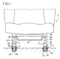
Comme montré à la figure 1, la structure du siège 2 est solidaire
d'un piétement composé de deux flasques respectivement, de guidage 3 et de
rattrapage 4, comportant des moyens coopérant avec des glissières
longitudinales 6. Dans la forme d'exécution représentée, en particulier figure 2,
chaque glissière présente, en section transversale, la forme générale d'un
« U » dont les deux ailes verticales 7a, 7b sont verticales et sont munies à
leurs extrémités supérieures, d'une part, d'un retour interne respectivement 8a,
8b, d'autre part, d'un retour externe 9a, 9b, et de plus, d'une face plane
supérieure 10a, 10b, formant chemin de roulement, mais pouvant aussi former
chemin de glissement.As shown in Figure 1, the structure of the
Les figures 2 à 4 montrent que chacun des flasques présente, en
vue de côté, la forme générale d'une crosse, c'est-à-dire présente une pointe
3a, 4a tournée vers l'avant, et une pointe 3b, 4b tournée vers l'arrière, séparée
par une partie centrale concave et comporte, dans chacune de ses pointes, un
alésage respectivement avant 12 et arrière 13 pour, respectivement, un axe de
liaison avec la structure du siège, et l'articulation 11 de la structure de dossier
14.Figures 2 to 4 show that each of the flanges has, in
side view, the general shape of a stick, i.e. has a
Chaque flasque est en forme de boítier ouvert vers l'intérieur.
L'ouverture de celui 3 est obturée par une tôle de fermeture 15 comportant des
nervures de rigidification. Cette tôle est liée au flasque 3 par des moyens de
liaison démontable, tels que vis, matérialisés par des traits mixtes 16 (figure 2).Each flange is in the form of a box open inwards.
The opening of that 3 is closed by a
Comme montré plus en détails figure 5, le flasque de guidage 3 porte directement :
- à ses extrémités, des plaquettes verticales et transversales 19 facilitant son positionnement dans la glissière correspondante,
- un
verrou 20 monté pivotant autour d'un axe géométrique parallèle à l'axe longitudinal du flasque et de la glissière, - des crochets de
retenue 22, également montés pivotants autour d'un axe géométrique longitudinal, - une
coulisse 23 de commande de pivotement duverrou 20, et descrochets 22, - des moyens de rappel à
ressort 24 de lacoulisse 23, - des
moyens 25 de calage de lacoulisse 23 dans sa position correspondant au blocage duverrou 20 et descrochets 22 dans une position de dégagement, permettant leur engagement ou dégagement de la glissière, - et un levier intermédiaire 26, articulé sur le flasque autour d'un
axe transversal 27 et dont l'extrémité inférieure vient en appui sur la face en
bout avant 23a de la
coulisse 23.
- at its ends, vertical and
transverse plates 19 facilitating its positioning in the corresponding slide, - a
lock 20 mounted pivoting about a geometric axis parallel to the longitudinal axis of the flange and of the slide, - retaining
hooks 22, also pivotally mounted about a longitudinal geometric axis, - a
slide 23 for controlling the pivoting of thelatch 20, and hooks 22, - spring return means 24 of the
slide 23, - means 25 for wedging the
slide 23 in its position corresponding to the blocking of thelatch 20 and of thehooks 22 in a release position, allowing them to be engaged or released from the slide, - and an
intermediate lever 26, articulated on the flange around atransverse axis 27 and the lower end of which bears on thefront end face 23a of theslide 23.
Comme montré schématiquement à la figure 1, l'extrémité
supérieure du levier 26 reçoit l'appui d'un ergot radial 28, calé sur un tourillon
29 d'une barre de commande 30 s'étendant sous le siège 2. Ce tourillon est
monté libre en rotation dans l'alésage 32 du flasque, visible à la figure 5.As shown schematically in Figure 1, the end
upper of
Enfin, la flasque 3 porte deux paliers, respectivement avant 33 et
arrière 34 recevant, comme montré figure 2, un axe respectivement 35 et 36
dont l'extrémité forme portée de guidage pour un galet, respectivement 37, 38.
Ces deux galets viennent en appui sur les chemins de roulement de la glissière
correspondante, à savoir sur le chemin de roulement 10a pour le galet 38, et
sur le chemin de roulement 10b de la même glissière pour le galet 37.Finally, the
La description détaillée des éléments 20 à 25 portés par le flasque
3 sera reprise ultérieurement par comparaison avec les éléments similaires du
flasque de rattrapage 4. The detailed description of the
En effet, et comme montré de manière générale à la figure 4, dans
le flasque de rattrapage 4 les moyens de positionnement, les moyens de
guidage en translation longitudinale et les moyens de verrouillage, sont portés
par deux chariots, respectivement, antérieur 40 et postérieur 41.Indeed, and as shown generally in Figure 4, in
the take-
Comme montré, en détails, aux figures 7 et 10 à 14, le chariot
postérieur 41 comprend un corps 42 présentant, en section transversale, la
forme générale d'un « U » dont l'âme 42a est traversée longitudinalement par
des alésages cylindriques, respectivement 43 et 44, transversalement par deux
alésages cylindriques 45 et verticalement par deux logements traversant 46,
47. Les deux ailes 42b sont traversées, chacune, par un alésage transversal 48
et comportent chacune une rainure longitudinale interne 49 faisant vis à vis à la
rainure de l'autre aile. Le logement 46 contient un verrou 120, identique au
verrou 20 du flasque 3. Ce verrou est articulé autour d'un axe 50 (figure 11),
disposé dans l'alésage longitudinal 44. Il s'étend verticalement vers le bas et sa
partie inférieure, pénétrant dans l'intervalle entre les deux ailes 7a, 7b de la
glissière, comme montré à la figure 11, est aménagée en forme de crochet, et
en particulier, en forme de crochet double 52. Chacun de ces crochets est
destiné à pénétrer dans l'une des encoches 53 ménagées, comme montré
figure 2, dans chacune des ailes 7a, 7b de la glissière correspondante. Ces
crochets sont associés à un redan supérieur 54, formant pêne de retenue. Ce
pêne est apte, en cas de choc, à venir en appui sous le retour interne
correspondant 8a ou 8b de la glissière pour retenir le piétement et le siège.As shown in detail in Figures 7 and 10-14, the carriage
posterior 41 comprises a
Dans sa partie supérieure, le verrou 120 est solidaire d'un doigt
radial 55, saillant vers le haut.In its upper part, the
Le logement 47 du corps 42 de chariot contient un crochet de
retenue 122, de forme identique au crochet 22 du flasque de guidage 3.
Comme montré figure 13, ce crochet est articulé sur un axe 56, disposé dans
l'alésage 43 du corps. A sa partie inférieure, il comporte un redan 57 formant
crochet et apte, comme le redan 54 du verrou, à venir au-dessous du retour
interne 8a, 8b de la glissière correspondante. A sa partie supérieure, il est muni
d'un doigt radial 58, saillant vers le haut.The
Comme montré à la figure 7, les alésages 45 du corps sont
destinés à recevoir deux axes transversaux 59 servant de pivots pour deux
roulettes 60.As shown in Figure 7, the
Dans la forme d'exécution représentée aux figures 10 et 14,
chaque axe 59 guide en rotation la roulette 60 correspondante par une portée
cylindrique 62 qui est excentrée d'une valeur e par rapport à son axe
géométrique. A son autre extrémité, l'axe 59 est équipé d'un méplat 63
permettant de repérer la position angulaire de cet axe, donc de la portée
excentrique, et en conséquence, de procéder au réglage de la position de l'axe
de rotation de la roulette par rapport au chariot. La fente 59a, ménagée dans la
tête 59b de l'axe, participe également au repérage de la position de réglage de
la roulette.In the embodiment shown in Figures 10 and 14, each
Après réglage, l'axe 59 est bloqué en position, par exemple, par un
écrou 64.After adjustment, the
Enfin, comme montré figure 12, les alésages 48 ménagés dans les
ailes 42b du corps de chariot servent de logements à des paliers 66 pour un
axe traversant 65. Les extrémités de cet axe 65 sont portées par des alésages
67 ménagés, l'un dans la partie inférieure du flasque 4 et l'autre dans une joue
68 disposée parallèlement au flasque et liée à lui par une paroi 69. Le flasque,
la joue et la paroi forment une coiffe en « U » retourné contenant les chariots.Finally, as shown in FIG. 12, the
La figure 12 montre bien que l'intervalle I entre le flasque 4 et sa
paroi 68 est supérieur à la largeur L du chariot 41, de manière que soient
ménagés, de chaque côté du chariot, des jeux Ja, Jb, lui permettant de se
déplacer transversalement en lui donnant son caractère flottant. Une lame
ressort pliée en « V » 71 est liée par sa branche 71a à la joue 68 et prend
appui, par sa branche 71 b, sur le chariot 41 pour le ramener dans une position
sensiblement médiane, facilitant son engagement dans la glissière dans la
phase de mise en place du siège.FIG. 12 clearly shows that the interval I between the
Enfin, le chariot 41 est équipé d'un moyen de positionnement qui,
dans la forme d'exécution représentée, est constitué par une coiffe en matière
plastique 70, formant une sorte de boítier de protection des éléments pivotants
du chariot qui, le traversent par des ouvertures appropriées, mais il est évident
que ces moyens de positionnement peuvent présenter toute autre forme et, par
exemple, être constitués par une plaquette en matière plastique présentant la
même section transversale que la coiffe, mais rapportée sur le chariot.Finally, the
Le chariot 40, visible figures 7 et 8, comprend un corps 142 ayant
la même section transversale que le corps 42 du chariot 41 et dont l'âme 142a
est traversée par deux alésages longitudinaux 143, 144 et par un logement
vertical traversant 147 pour un crochet de retenue 122. Comme montré figure
7, l'âme 142a est également traversée par un alésage transversal pour un axe
59 recevant une roulette 60. Les deux ailes 142b du corps sont traversées par
des alésages transversaux alignés deux à deux et recevant chacun un palier
66. Comme le montre la figure 8, dans ces paliers sont montés deux axes
transversaux 73. Chaque axe est disposé, par ses extrémités, dans des
alésages 74 ménagés dans le flasque 4 et dans sa joue 68. Ces deux axes
forment des glissières sur lesquelles le chariot 40 peut coulisser
transversalement pour s'adapter aux différences de position transversale de la
glissière par rapport au siège ou inversement. Une lame ressort 75 assure la
même fonction que la lame 71 de l'autre chariot 41.The
Ce chariot 40 comporte aussi des rainures longitudinales 149,
ménagées dans ses ailes et se faisant vis à vis.This
Comme le verrou 20 et les crochets de retenue 22 du flasque de
guidage 3, le verrou 120 et les doigts de retenue 122 du flasque de rattrapage
4 ont un pivotement qui est commandé par une coulisse 123, disposée au-dessus
d'eux. Comme montré figure 7, cette coulisse comporte, dans son âme,
une lumière 76 et deux lumières 77. La glissière est munie à ses extrémités de
roulettes 78 circulant dans les rainures 49 et 149 ménagées dans les ailes des
deux chariots 40, 41.As the
Lorsque la coulisse est en place, les lumières 76, 77 sont
traversées, chacune, par l'un des doigts 55, 58, respectivement du verrou et
des crochets de retenue, comme montré aux figures 8, 11 et 13. Les bords de
ces lumières forment des rampes qui, lors du déplacement de la coulisse,
peuvent venir en contact avec le doigt correspondant, pour le déplacer
transversalement et provoquer le pivotement du verrou ou crochet
correspondant.When the slide is in place, the
La figure 7 fait bien apparaítre que la lumière 76 pour le verrou 120
est inclinée transversalement sur toute sa longueur, par rapport à l'axe
longitudinal de la coulisse 123 et présente des bords sensiblement rectilignes,
alors que les lumières 77 pour les crochets 122 sont composées chacune d'un
tronçon longitudinal 77a et d'un tronçon incliné 77b. Chaque tronçon
longitudinal 77a a une longueur au moins égale à la course de déplacement
longitudinal que doit effectuer la coulisse 123 pour amener le verrou de sa
position de verrouillage à sa position de déverrouillage.Figure 7 shows that the light 76 for the
Ainsi, lorsque la coulisse 123 est déplacée pour commander le
basculement du verrou 120 de sa position de verrouillage à sa position de
déverrouillage, les crochets de retenue 122 ne sont pas pivotés, puisque alors
leurs doigts 58 circulent dans la partie longitudinale 77a des lumières 77, tandis
que, lorsque la coulisse est déplacée pour amener le verrou 120 de sa position
de déverrouillage à une position de dégagement et d'extraction, représentée en
traits mixtes à la figure 11, les crochets 122 sont amenés par pivotement dans
la position d'extraction représentée en traits mixtes figure 17, par coopération
de leurs doigts 58 avec les bords des parties inclinées 77b des lumières 77.When the
Comme montré à la figure 7, la coulisse est solidaire d'un doigt
d'accrochage 81 saillant vers le haut et sur lequel est accrochée l'une des
extrémités d'un ressort de traction 79, accroché, par son autre extrémité, à un
point fixe du flasque et, par exemple, à un axe 73, comme montré à la figure 8.As shown in Figure 7, the slide is secured to a
Dans sa partie inférieure, la coulisse 123 est équipée d'un talon 80,
apte à coopérer avec une barrette de calage 82 faisant partie d'un palpeur de
présence de la glissière.In its lower part, the
Dans la forme d'exécution représentée figures 4 et 7, ce palpeur
est constitué par un levier coudé 83, monté pivotant sur un axe transversal 84
tourillonnant dans le flasque 4 et sa joue 68. Ce levier porte la barrette 82, à
l'extrémité de sa branche sensiblement horizontale, tandis que l'extrémité de
sa branche sensiblement verticale est équipée d'une roulette 85. Lorsque la
coulisse est manoeuvrée pour amener le verrou 120 et les leviers 122 en
position d'extraction, et est déplacée dans le sens de la flèche 91 à l'encontre
de l'effort de rappel du ressort 79, son talon 80 passe sur la barrette 82 qui
bascule et s'efface. Dès que ce déplacement est terminé, la coulisse est
ramenée par le ressort 79 jusqu'à ce que le talon 80 vienne en butée sur la
barrette 82, en assurant ainsi l'immobilisation en position d'extraction du verrou
120 et des crochets 122. Cela facilite l'extraction du siège par rapport à la
glissière et ultérieurement la remise en place des verrous et crochets dans la
glissière, tout en évitant de former, sur le piétement du siège, des
protubérances pouvant accrocher d'autres éléments.In the embodiment shown in Figures 4 and 7, this probe
consists of a
Le déplacement de la coulisse 123 est assuré par un levier 126,
visible à la figure 3, et articulé sur le flasque 4 par un axe 127. Ce levier 126
est actionné simultanément au levier 26 par la même barre de commande 30.The displacement of the
La figure 5 montre que la coulisse 23 du flasque de guidage 3 est
montée coulissante sur des glissières cylindriques 86 et 87 s'étendant entre
des ailes transversales 3c du flasque, et que le rappel de la glissière est assuré
par le ressort 24 qui est disposé autour de la glissière 87. La coulisse comporte
également des lumières 76, 77 qui commandent le basculement du verrou 20
et des crochets de retenue 22 en coopérant avec les doigts de ces éléments. FIG. 5 shows that the
Les moyens de blocage de la coulisse 23, dans sa position de
maintien du verrou 20 et des crochets 22 en position d'extraction, sont réalisés
différemment, comme montré plus en détails à la figure 15. Les moyens de
palpage, venant en contact avec la glissière lorsque le siège est amené sur
celle-ci sont constitués par un piston 88, monté coulissant dans un alésage
vertical épaulé 89, ménagé dans une excroissance 90 du flasque 3. La tige
88a du piston 88 est liée, par exemple par une goupille transversale 92, à un
doigt transversal 93 s'étendant au-dessus de la trajectoire de la coulisse 23. Un
ressort 91, interposé entre le piston 88 et le fond du logement 89, sollicite en
permanence ce piston vers le bas, de manière que son doigt 93 vienne en
appui sur le bord de la coulisse 23. Ce bord est équipé localement d'un cran
94, visible figure 5, qui reçoit le doigt 93 lorsque la coulisse est déplacée pour
commander la mise en position de dégagement et d'extraction du verrou 20 et
des crochets de retenue 22. A l'inverse, lors de la mise en place du siège sur
les glissières, le contact de l'extrémité du piston 88 avec le chemin de
roulement de la glissière provoque la rétraction du piston 88 dans son
logement 89 et le dégagement de son doigt 93 du cran 94, c'est-à-dire permet
au ressort de rappel 24 de provoquer le déplacement de la coulisse pour
amener automatiquement le verrou 20 et les crochets de retenue 22 en
position, respectivement de verrouillage et de retenue verticale du piétement
du siège. L'extrémité du piston 88 est munie d'une roulette 95 pour éviter que
les déplacements de réglage du piétement sur la glissière soient freinés par le
contact de ce piston avec la glissière et que la glissière soit rayée par ce
piston.The locking means of the
Lorsqu'un siège équipé de ce dispositif de guidage et d'ancrage est
mis en place sur deux glissières parallèles, son positionnement s'effectue très
aisément par les plaquettes 19 équipant le flasque 3 et les boítiers 70 équipant
les chariots du flasque de rattrapage 4. Dès que les verrous 20, 120 et les
crochets de retenue 22, 122 sont engagés entre les ailes des deux glissières,
et que les palpeurs, respectivement 88, 83, détectent la présence des
glissières et libèrent les coulisses 23, 123, les ressorts 24, 79 sollicitant ces
coulisses provoquent le déplacement longitudinal de celles-ci et, en
conséquence, la mise en position de verrouillage des verrous et la mise en
position de retenue des crochets. Il suffit alors de déplacer légèrement le siège
jusqu'à ce que les crochets double 52 pénètrent dans les encoches 53 des
glissières et assurent le verrouillage. When a seat fitted with this guidance and anchoring device is
placed on two parallel slides, its positioning is very
easily by the
Pour régler la position du siège, il suffit d'actionner la barre de
commande 30 pour provoquer le déplacement des leviers 26 et 126 et le
déplacement des coulisses 23, 123 amenant les seuls verrous 22, 122 dans
leur seule position de déverrouillage. Lors du déplacement du chariot
longitudinal du siège sur les glissières, le flasque de guidage 3 coopère avec
sa glissière pour assurer le guidage en translation de ce déplacement, tandis
que les chariots flottants 40 et 41 du flasque de rattrapage 4 absorbent, par
leur déplacement transversal, la variation de distance entre les deux glissières
et que, simultanément, le chariot pivotant 41 absorbe, par son pivotement, les
variations de niveau de la face supérieure de la glissière sur laquelle il roule.To adjust the position of the seat, simply activate the
Enfin, et pour compléter les réglages effectués au montage par
pivotement des portées excentriques 62 sur lesquelles sont montées les
roulettes 37, 38 et 60, des chariots 40, 41 et éventuellement, celles portant les
roulettes 37, 38 du flasque de guidage, ces roulettes sont choisies parmi une
série de roulettes ayant le même diamètre d'alésage, mais ayant des diamètres
extérieurs allant en croissant par palier de valeur au plus égale à celle de
l'excentration e de la portée excentrée. Ainsi, par exemple, si la portée
cylindrique a un diamètre de 12 millimètres et est excentrée de 4 millimètres
par rapport à l'axe 59 ayant un diamètre de 8 millimètres, les roulettes 37, 38 et
60, ayant un diamètre nominal de 26 millimètres, sont choisies parmi des
roulettes ayant des diamètres de 23, 26 et 29 millimètres.Finally, and to complete the adjustments made to the pivoting mounting of the
Dans une variante de réalisation, non représentée, le flasque de
rattrapage porte un unique chariot, similaire au chariot 40, mais plus long, et lié
au flasque par un seul axe d'articulation. Les extrémités avant et arrière du
flasque reposent sur celles du chariot avec interposition de moyens
amortisseurs du mouvement de pivotement, ces moyens étant associés à des
butées limitant la course de pivotement.In an alternative embodiment, not shown, the flange of
retrofit carries a single carriage, similar to
Claims (9)
Applications Claiming Priority (2)
| Application Number | Priority Date | Filing Date | Title |
|---|---|---|---|
| FR0010228 | 2000-07-27 | ||
| FR0010228A FR2812251B1 (en) | 2000-07-27 | 2000-07-27 | GUIDANCE AND ANCHORING DEVICE FOR REMOVABLE VEHICLE SEAT |
Publications (2)
| Publication Number | Publication Date |
|---|---|
| EP1176047A1 true EP1176047A1 (en) | 2002-01-30 |
| EP1176047B1 EP1176047B1 (en) | 2002-11-27 |
Family
ID=8853251
Family Applications (1)
| Application Number | Title | Priority Date | Filing Date |
|---|---|---|---|
| EP20010420158 Expired - Lifetime EP1176047B1 (en) | 2000-07-27 | 2001-07-12 | Device for guiding and anchoring removable vehicle seats |
Country Status (5)
| Country | Link |
|---|---|
| EP (1) | EP1176047B1 (en) |
| DE (1) | DE60100054T2 (en) |
| ES (1) | ES2187493T3 (en) |
| FR (1) | FR2812251B1 (en) |
| PT (1) | PT1176047E (en) |
Cited By (37)
| Publication number | Priority date | Publication date | Assignee | Title |
|---|---|---|---|---|
| EP1334865A2 (en) * | 2002-02-08 | 2003-08-13 | Grupo Antolin-Ingenieria, S.A. | Veritcal and automatic alignment device for a vehicle seat |
| EP1407920A2 (en) * | 2002-10-09 | 2004-04-14 | Koller Engineering Limited | Anchorage systems |
| WO2006017633A1 (en) | 2004-08-05 | 2006-02-16 | Johnson Controls Technology Company | Sliding latch system |
| DE102009039349A1 (en) | 2009-08-29 | 2010-03-25 | Daimler Ag | Seat bolting device for locking rear seat in e.g. passenger car, has clamping rail detached from guide rail in moving position of activation lever such that snapping unit is detached along with clamping rail |
| EP2298590A1 (en) | 2009-09-21 | 2011-03-23 | Grupo Antolin-Ingenieria, S.A. | Anchoring device for a removable automobile seat |
| DE102009042597A1 (en) * | 2009-09-23 | 2011-03-24 | Hydac Accessories Gmbh | Locking system for carrier slide for moving tool in preset positions, has lock body moved to release position in which body is lifted from wall against pre-stress by release element |
| WO2012025539A1 (en) * | 2010-08-23 | 2012-03-01 | Johnson Controls Gmbh | Longitudinal adjusting device for a vehicle seat, comprising a separable upper and lower rail |
| CN103241146A (en) * | 2012-02-10 | 2013-08-14 | 格鲁坡安托林-英杰尼瑞亚股份有限公司 | Anchoring mechanism (1) of a detachable vehicle seat |
| EP3162614A1 (en) | 2015-10-27 | 2017-05-03 | Grupo Antolin-Ingenieria, S.A. | Seat for motor vehicle having a mechanism to reduce sliding |
| WO2019174720A1 (en) * | 2018-03-13 | 2019-09-19 | Pressan Madeni Esya San. Tic. A.S. | Vehicle seat mounting arrangement |
| FR3080804A1 (en) * | 2018-05-04 | 2019-11-08 | Lear Corporation | ANCHOR MODULE |
| CN110435492A (en) * | 2018-05-04 | 2019-11-12 | 李尔公司 | Support component |
| US10562414B2 (en) | 2018-05-04 | 2020-02-18 | Lear Corporation | Track assembly |
| US20200086997A1 (en) * | 2018-09-18 | 2020-03-19 | Rockwell Collins, Inc. | Dynamic Retention System for an Aircraft Seat |
| WO2020151787A1 (en) * | 2019-01-22 | 2020-07-30 | Grammer Ag | Guide device with locking device |
| US10855037B2 (en) | 2018-12-17 | 2020-12-01 | Lear Corporation | Support assembly with a support member and a track assembly |
| US10882420B2 (en) | 2019-03-08 | 2021-01-05 | Lear Corporation | Track assembly |
| US10906431B2 (en) | 2018-05-04 | 2021-02-02 | Lear Corporation | Track assembly |
| US10926667B2 (en) | 2018-05-04 | 2021-02-23 | Lear Corporation | Track assembly |
| US10950977B2 (en) | 2018-12-18 | 2021-03-16 | Lear Corporation | Track assembly for a vehicle component |
| US11007905B2 (en) * | 2018-07-04 | 2021-05-18 | Magna Seating (Germany) Gmbh | Blocking and contact system for the electrical connection of an on-board power supply of a motor vehicle to a removable vehicle seat or a seat system |
| US11040638B2 (en) | 2018-05-04 | 2021-06-22 | Lear Corporation | Track assembly |
| US11040639B2 (en) | 2018-05-04 | 2021-06-22 | Lear Corporation | Track assembly |
| US11040653B2 (en) | 2019-02-25 | 2021-06-22 | Lear Corporation | Track assembly |
| US11117538B2 (en) | 2018-12-17 | 2021-09-14 | Lear Corporation | Electrical assembly |
| US11225201B2 (en) | 2018-12-10 | 2022-01-18 | Lear Corporation | Track assembly |
| US11299075B2 (en) | 2019-03-06 | 2022-04-12 | Lear Corporation | Electrical assembly |
| US11323114B2 (en) | 2019-10-04 | 2022-05-03 | Lear Corporation | Electrical system |
| US11358497B2 (en) | 2018-05-04 | 2022-06-14 | Lear Corporation | Track system having a rolling member |
| US11440482B2 (en) | 2018-12-10 | 2022-09-13 | Lear Corporation | Track assembly |
| US11463083B2 (en) | 2019-10-04 | 2022-10-04 | Lear Corporation | Electrical system |
| US11506272B2 (en) | 2020-02-21 | 2022-11-22 | Lear Corporation | Track system with a support member |
| US11505141B2 (en) | 2020-10-23 | 2022-11-22 | Lear Corporation | Electrical system with track assembly and support assembly |
| US11613220B2 (en) | 2018-12-17 | 2023-03-28 | Lear Corporation | Electrical assembly |
| US11634101B2 (en) | 2019-10-04 | 2023-04-25 | Lear Corporation | Removable component system |
| US11708011B2 (en) | 2021-03-05 | 2023-07-25 | Camaco, Llc. | Reinforced track assembly for vehicle seat |
| US11807142B2 (en) | 2019-03-06 | 2023-11-07 | Lear Corporation | Electrical track assembly |
Families Citing this family (9)
| Publication number | Priority date | Publication date | Assignee | Title |
|---|---|---|---|---|
| FR2837149B1 (en) | 2002-03-15 | 2004-06-25 | Antolin Grupo Ing Sa | PARALLELISM FAULT COMPENSATOR FOR REMOVABLE VEHICLE SEAT |
| DE102004025506B4 (en) * | 2004-05-21 | 2010-04-08 | Johnson Controls Gmbh | Control device for a vehicle seat |
| DE102004035480B4 (en) | 2004-07-14 | 2018-03-01 | Volkswagen Ag | rail arrangement |
| DE102005043552A1 (en) * | 2005-09-12 | 2007-03-15 | GM Global Technology Operations, Inc., Detroit | Motor vehicle with a seat |
| DE102008039621A1 (en) * | 2008-08-25 | 2010-03-04 | GM Global Technology Operations, Inc., Detroit | Seat fastener for attaching seat to base of motor vehicle, has stabilizing element provided between seat clamp and carrier in mounting position for increasing pressing surface at carrier during crash of motor vehicle |
| DE102009038126B4 (en) * | 2009-08-11 | 2018-12-13 | Adient Luxembourg Holding S.À R.L. | Longitudinal adjuster for a vehicle seat |
| DE102010021662A1 (en) | 2010-05-26 | 2011-12-01 | Daimler Ag | Adjuster, particularly for vehicle seat, comprises bottom rail and upper rail which is moved relative to bottom rail, where locking device is provided with locking element which is brought in locking position from release position |
| DE102019120194A1 (en) * | 2019-07-25 | 2021-01-28 | Aguti Produktentwicklung & Design Gmbh | Device for mounting a seat arrangement in a vehicle and vehicle |
| DE102021104010B4 (en) | 2020-02-21 | 2024-01-11 | Lear Corporation | Rail system with a support element and anchor for a support element of a rail system |
Citations (4)
| Publication number | Priority date | Publication date | Assignee | Title |
|---|---|---|---|---|
| EP0925996A1 (en) * | 1997-12-22 | 1999-06-30 | Bertrand Faure Equipements S.A. | Vehicle seat assembly with removable seat mounted on slides |
| EP0947380A1 (en) * | 1998-03-30 | 1999-10-06 | Renault | Rack device built on the rail bottom |
| EP0949111A1 (en) * | 1998-04-06 | 1999-10-13 | Renault | Modular anchoring system with cam control |
| EP0976605A1 (en) * | 1998-07-31 | 2000-02-02 | Grupo Antolin-Ingenieria S.A. | Vehicle seat, removable, reversible and longitudinally adjustable by actuators on its slides |
-
2000
- 2000-07-27 FR FR0010228A patent/FR2812251B1/en not_active Expired - Fee Related
-
2001
- 2001-07-12 ES ES01420158T patent/ES2187493T3/en not_active Expired - Lifetime
- 2001-07-12 DE DE2001600054 patent/DE60100054T2/en not_active Expired - Lifetime
- 2001-07-12 PT PT01420158T patent/PT1176047E/en unknown
- 2001-07-12 EP EP20010420158 patent/EP1176047B1/en not_active Expired - Lifetime
Patent Citations (4)
| Publication number | Priority date | Publication date | Assignee | Title |
|---|---|---|---|---|
| EP0925996A1 (en) * | 1997-12-22 | 1999-06-30 | Bertrand Faure Equipements S.A. | Vehicle seat assembly with removable seat mounted on slides |
| EP0947380A1 (en) * | 1998-03-30 | 1999-10-06 | Renault | Rack device built on the rail bottom |
| EP0949111A1 (en) * | 1998-04-06 | 1999-10-13 | Renault | Modular anchoring system with cam control |
| EP0976605A1 (en) * | 1998-07-31 | 2000-02-02 | Grupo Antolin-Ingenieria S.A. | Vehicle seat, removable, reversible and longitudinally adjustable by actuators on its slides |
Cited By (62)
| Publication number | Priority date | Publication date | Assignee | Title |
|---|---|---|---|---|
| EP1334865A2 (en) * | 2002-02-08 | 2003-08-13 | Grupo Antolin-Ingenieria, S.A. | Veritcal and automatic alignment device for a vehicle seat |
| FR2835790A1 (en) * | 2002-02-08 | 2003-08-15 | Antolin Grupo Ing Sa | DEVICE FOR VERTICAL AND AUTOMATIC SETTING OF A VEHICLE SEAT |
| US6736458B2 (en) | 2002-02-08 | 2004-05-18 | Grupo Antolin-Ingenieria, S.A. | Device for the vertical and automatic wedging of a vehicle seat |
| EP1334865A3 (en) * | 2002-02-08 | 2004-06-09 | Grupo Antolin-Ingenieria, S.A. | Veritcal and automatic alignment device for a vehicle seat |
| EP1407920A2 (en) * | 2002-10-09 | 2004-04-14 | Koller Engineering Limited | Anchorage systems |
| EP1407920A3 (en) * | 2002-10-09 | 2005-03-23 | Koller Engineering Limited | Anchorage systems |
| US8109577B2 (en) | 2004-08-05 | 2012-02-07 | Johnson Controls Technology Company | Sliding latch system |
| US7819475B2 (en) | 2004-08-05 | 2010-10-26 | Johnson Controls Technology Company | Sliding latching system |
| WO2006017633A1 (en) | 2004-08-05 | 2006-02-16 | Johnson Controls Technology Company | Sliding latch system |
| DE102009039349A1 (en) | 2009-08-29 | 2010-03-25 | Daimler Ag | Seat bolting device for locking rear seat in e.g. passenger car, has clamping rail detached from guide rail in moving position of activation lever such that snapping unit is detached along with clamping rail |
| EP2298590A1 (en) | 2009-09-21 | 2011-03-23 | Grupo Antolin-Ingenieria, S.A. | Anchoring device for a removable automobile seat |
| FR2950292A1 (en) * | 2009-09-21 | 2011-03-25 | Antolin Grupo Ing Sa | REMOVABLE SEAT ANCHORING DEVICE OF A MOTOR VEHICLE |
| DE102009042597A1 (en) * | 2009-09-23 | 2011-03-24 | Hydac Accessories Gmbh | Locking system for carrier slide for moving tool in preset positions, has lock body moved to release position in which body is lifted from wall against pre-stress by release element |
| US9701217B2 (en) | 2010-08-23 | 2017-07-11 | Johnson Controls Gmbh | Longitudinal adjusting device for a vehicle seat, comprising a separable upper and lower rail |
| CN103068621A (en) * | 2010-08-23 | 2013-04-24 | 约翰逊控股公司 | Longitudinal adjusting device for a vehicle seat, comprising a separable upper and lower rail |
| CN103068621B (en) * | 2010-08-23 | 2016-05-11 | 约翰逊控股公司 | Comprise the longitudinal adjusting device of separable upper and lower portion track for seat |
| WO2012025539A1 (en) * | 2010-08-23 | 2012-03-01 | Johnson Controls Gmbh | Longitudinal adjusting device for a vehicle seat, comprising a separable upper and lower rail |
| CN103241146A (en) * | 2012-02-10 | 2013-08-14 | 格鲁坡安托林-英杰尼瑞亚股份有限公司 | Anchoring mechanism (1) of a detachable vehicle seat |
| FR2986751A1 (en) * | 2012-02-10 | 2013-08-16 | Antolin Grupo Ing Sa | MECHANISM FOR ANCHORING A REMOVABLE SEAT |
| CN103241146B (en) * | 2012-02-10 | 2017-09-19 | 格鲁坡安托林-英杰尼瑞亚股份有限公司 | Anchoring mechanism for dismountable seat |
| EP3162614A1 (en) | 2015-10-27 | 2017-05-03 | Grupo Antolin-Ingenieria, S.A. | Seat for motor vehicle having a mechanism to reduce sliding |
| WO2019174720A1 (en) * | 2018-03-13 | 2019-09-19 | Pressan Madeni Esya San. Tic. A.S. | Vehicle seat mounting arrangement |
| CN112135750B (en) * | 2018-03-13 | 2023-12-12 | 普善金属制品工业与贸易公司 | Vehicle seat mounting assembly |
| US20210016685A1 (en) * | 2018-03-13 | 2021-01-21 | Pressan Madeni Esya San. Tic. A.S. | Vehicle seat mounting arrangement |
| CN112135750A (en) * | 2018-03-13 | 2020-12-25 | 普善金属制品工业与贸易公司 | Vehicle seat mounting assembly |
| US10850645B2 (en) | 2018-05-04 | 2020-12-01 | Lear Corporation | Track assembly |
| US10926667B2 (en) | 2018-05-04 | 2021-02-23 | Lear Corporation | Track assembly |
| FR3080804A1 (en) * | 2018-05-04 | 2019-11-08 | Lear Corporation | ANCHOR MODULE |
| US10759308B2 (en) | 2018-05-04 | 2020-09-01 | Lear Corporation | Support assembly |
| US10850644B2 (en) | 2018-05-04 | 2020-12-01 | Lear Corporation | Support assembly with cam assembly |
| US11040639B2 (en) | 2018-05-04 | 2021-06-22 | Lear Corporation | Track assembly |
| US11040638B2 (en) | 2018-05-04 | 2021-06-22 | Lear Corporation | Track assembly |
| US10562414B2 (en) | 2018-05-04 | 2020-02-18 | Lear Corporation | Track assembly |
| US11358497B2 (en) | 2018-05-04 | 2022-06-14 | Lear Corporation | Track system having a rolling member |
| US10889208B2 (en) | 2018-05-04 | 2021-01-12 | Lear Corporation | Track assembly |
| CN110435492A (en) * | 2018-05-04 | 2019-11-12 | 李尔公司 | Support component |
| US10906431B2 (en) | 2018-05-04 | 2021-02-02 | Lear Corporation | Track assembly |
| US11007905B2 (en) * | 2018-07-04 | 2021-05-18 | Magna Seating (Germany) Gmbh | Blocking and contact system for the electrical connection of an on-board power supply of a motor vehicle to a removable vehicle seat or a seat system |
| US10906650B2 (en) | 2018-09-18 | 2021-02-02 | Rockwell Collins, Inc. | Dynamic retention system for an aircraft seat |
| EP3626618A1 (en) * | 2018-09-18 | 2020-03-25 | Rockwell Collins, Inc. | Dynamic retention system for an aircraft seat |
| US20200086997A1 (en) * | 2018-09-18 | 2020-03-19 | Rockwell Collins, Inc. | Dynamic Retention System for an Aircraft Seat |
| US11225201B2 (en) | 2018-12-10 | 2022-01-18 | Lear Corporation | Track assembly |
| US11440482B2 (en) | 2018-12-10 | 2022-09-13 | Lear Corporation | Track assembly |
| US11117538B2 (en) | 2018-12-17 | 2021-09-14 | Lear Corporation | Electrical assembly |
| US11613220B2 (en) | 2018-12-17 | 2023-03-28 | Lear Corporation | Electrical assembly |
| US10855037B2 (en) | 2018-12-17 | 2020-12-01 | Lear Corporation | Support assembly with a support member and a track assembly |
| US10950977B2 (en) | 2018-12-18 | 2021-03-16 | Lear Corporation | Track assembly for a vehicle component |
| CN113474212A (en) * | 2019-01-22 | 2021-10-01 | 大众汽车股份公司 | Guide device with locking device |
| WO2020151787A1 (en) * | 2019-01-22 | 2020-07-30 | Grammer Ag | Guide device with locking device |
| DE102019000381B4 (en) | 2019-01-22 | 2023-04-27 | Volkswagen Aktiengesellschaft | Guide device with locking device |
| US11040653B2 (en) | 2019-02-25 | 2021-06-22 | Lear Corporation | Track assembly |
| US11299075B2 (en) | 2019-03-06 | 2022-04-12 | Lear Corporation | Electrical assembly |
| US11807142B2 (en) | 2019-03-06 | 2023-11-07 | Lear Corporation | Electrical track assembly |
| US10882420B2 (en) | 2019-03-08 | 2021-01-05 | Lear Corporation | Track assembly |
| US11323114B2 (en) | 2019-10-04 | 2022-05-03 | Lear Corporation | Electrical system |
| US11634101B2 (en) | 2019-10-04 | 2023-04-25 | Lear Corporation | Removable component system |
| US11463083B2 (en) | 2019-10-04 | 2022-10-04 | Lear Corporation | Electrical system |
| US11506272B2 (en) | 2020-02-21 | 2022-11-22 | Lear Corporation | Track system with a support member |
| US11835119B2 (en) | 2020-02-21 | 2023-12-05 | Lear Corporation | Track system with a support member |
| US11906028B2 (en) | 2020-02-21 | 2024-02-20 | Lear Corporation | Track system with a support member |
| US11505141B2 (en) | 2020-10-23 | 2022-11-22 | Lear Corporation | Electrical system with track assembly and support assembly |
| US11708011B2 (en) | 2021-03-05 | 2023-07-25 | Camaco, Llc. | Reinforced track assembly for vehicle seat |
Also Published As
| Publication number | Publication date |
|---|---|
| PT1176047E (en) | 2003-04-30 |
| DE60100054D1 (en) | 2003-01-09 |
| FR2812251A1 (en) | 2002-02-01 |
| FR2812251B1 (en) | 2003-01-03 |
| DE60100054T2 (en) | 2003-07-17 |
| ES2187493T3 (en) | 2003-06-16 |
| EP1176047B1 (en) | 2002-11-27 |
Similar Documents
| Publication | Publication Date | Title |
|---|---|---|
| EP1176047B1 (en) | Device for guiding and anchoring removable vehicle seats | |
| EP0945301B1 (en) | Slide for vehicle seat and seat equipped with such a slide | |
| EP0615879B1 (en) | Position adjusting device for motor vehicle seats | |
| EP0931689B1 (en) | Vehicle seat, removable, reversible and longitudinally adjustable | |
| CA2460630C (en) | Automobile seat rail | |
| EP0976605B1 (en) | Vehicle seat, removable, reversible and longitudinally adjustable by actuators on its slides | |
| FR2851211A1 (en) | Vehicle seat, has backrest rotatably mounted in accordance with rail and seat having interlocking device to selectively authorize rotation of backrest, and front with upper and lower end is rotatably mounted based on vehicle floor | |
| WO2008084156A2 (en) | Runner and seat provided with a locking system | |
| WO2005068247A2 (en) | Fixture for mounting a seat on a car floor by means of retractable guiding blocks | |
| EP0947380B1 (en) | Rack device built on the rail bottom | |
| CA2080145C (en) | Sliding channel for car seat with fixed return position | |
| EP1016359B1 (en) | Foldable table tennis table with locking means | |
| FR2853597A1 (en) | Slide shoe for vehicle seat, has retaining unit cooperating with indexing unit to held activation unit in unlocked position on preset range of longitudinal positions, and to move activation unit to locked position, outside range | |
| FR2882538A1 (en) | SLIDER FOR VEHICLE SEAT AND SEAT COMPRISING SUCH A SLIDER | |
| EP0800952A1 (en) | Forwardly displaceable automotive vehicle seat, to access the rear space | |
| FR3116771A1 (en) | Vehicle seat with reclining seat and backrests to facilitate access to the rear seats | |
| FR2881383A1 (en) | Backrest unit for motor vehicle seat has actuator for bringing carriage from normally locked position to release position and support with near end joined to carriage and far end for attachment to body part | |
| FR2892349A1 (en) | Motor vehicle seat, has positioning system controlling inactivation and maintaining of slide locking system, and anchorage unlocking control system maintained inactive till mobile and fixed profiles are in adjusting position | |
| EP3350016A1 (en) | Two-position locking device for a backrest of a rear seat of a motor vehicle | |
| FR2910392A1 (en) | Adjusting mechanism e.g. seat track, for motor vehicle, has mechanical sound characterizing system emitting audible sound in given relative position of sliding elements, while relative displacement is authorized by locking system | |
| FR2897092A1 (en) | Sliding side door guiding device for motor vehicle, has carriage whose parts pivot around articulation point to pivot connecting rod around articulation point under effect of thrust exerted by connecting rod | |
| FR3115244A1 (en) | Slider for a vehicle seat and vehicle seat comprising such a slider. | |
| FR2816556A1 (en) | Seat mechanism, for vehicle seat, consists of slider mechanism, with lock, with front foot of slider rail forming pivot and rear foot lockable to floor; locking mechanisms are linked to slide. | |
| FR2779686A1 (en) | Vehicle seat fittings for adjustable seat positioning | |
| FR2829440A1 (en) | Vehicle seat comprises seat part pivoted at front around rotational axis, two lockable rear bases and fold down back able to unlock bases when folded forwards |
Legal Events
| Date | Code | Title | Description |
|---|---|---|---|
| PUAI | Public reference made under article 153(3) epc to a published international application that has entered the european phase |
Free format text: ORIGINAL CODE: 0009012 |
|
| 17P | Request for examination filed |
Effective date: 20010720 |
|
| AK | Designated contracting states |
Kind code of ref document: A1 Designated state(s): AT BE CH CY DE DK ES FI FR GB GR IE IT LI LU MC NL PT SE TR Kind code of ref document: A1 Designated state(s): DE ES FR GB IT PT |
|
| AX | Request for extension of the european patent |
Free format text: AL;LT;LV;MK;RO;SI |
|
| GRAG | Despatch of communication of intention to grant |
Free format text: ORIGINAL CODE: EPIDOS AGRA |
|
| GRAG | Despatch of communication of intention to grant |
Free format text: ORIGINAL CODE: EPIDOS AGRA |
|
| GRAH | Despatch of communication of intention to grant a patent |
Free format text: ORIGINAL CODE: EPIDOS IGRA |
|
| 17Q | First examination report despatched |
Effective date: 20020606 |
|
| GRAH | Despatch of communication of intention to grant a patent |
Free format text: ORIGINAL CODE: EPIDOS IGRA |
|
| GRAA | (expected) grant |
Free format text: ORIGINAL CODE: 0009210 |
|
| AKX | Designation fees paid |
Free format text: DE ES FR GB IT PT |
|
| AK | Designated contracting states |
Kind code of ref document: B1 Designated state(s): DE ES FR GB IT PT |
|
| REG | Reference to a national code |
Ref country code: GB Ref legal event code: FG4D Free format text: NOT ENGLISH |
|
| GBT | Gb: translation of ep patent filed (gb section 77(6)(a)/1977) |
Effective date: 20021127 |
|
| REG | Reference to a national code |
Ref country code: IE Ref legal event code: FG4D Free format text: FRENCH |
|
| REF | Corresponds to: |
Ref document number: 60100054 Country of ref document: DE Date of ref document: 20030109 |
|
| REG | Reference to a national code |
Ref country code: PT Ref legal event code: SC4A Free format text: AVAILABILITY OF NATIONAL TRANSLATION Effective date: 20030226 |
|
| REG | Reference to a national code |
Ref country code: ES Ref legal event code: FG2A Ref document number: 2187493 Country of ref document: ES Kind code of ref document: T3 |
|
| REG | Reference to a national code |
Ref country code: IE Ref legal event code: FD4D Ref document number: 1176047E Country of ref document: IE |
|
| PLBE | No opposition filed within time limit |
Free format text: ORIGINAL CODE: 0009261 |
|
| STAA | Information on the status of an ep patent application or granted ep patent |
Free format text: STATUS: NO OPPOSITION FILED WITHIN TIME LIMIT |
|
| 26N | No opposition filed |
Effective date: 20030828 |
|
| PGFP | Annual fee paid to national office [announced via postgrant information from national office to epo] |
Ref country code: PT Payment date: 20110621 Year of fee payment: 11 |
|
| PGFP | Annual fee paid to national office [announced via postgrant information from national office to epo] |
Ref country code: GB Payment date: 20110516 Year of fee payment: 11 |
|
| PGFP | Annual fee paid to national office [announced via postgrant information from national office to epo] |
Ref country code: ES Payment date: 20110726 Year of fee payment: 11 |
|
| PGFP | Annual fee paid to national office [announced via postgrant information from national office to epo] |
Ref country code: IT Payment date: 20110721 Year of fee payment: 11 |
|
| REG | Reference to a national code |
Ref country code: PT Ref legal event code: MM4A Free format text: LAPSE DUE TO NON-PAYMENT OF FEES Effective date: 20130114 |
|
| GBPC | Gb: european patent ceased through non-payment of renewal fee |
Effective date: 20120712 |
|
| PG25 | Lapsed in a contracting state [announced via postgrant information from national office to epo] |
Ref country code: GB Free format text: LAPSE BECAUSE OF NON-PAYMENT OF DUE FEES Effective date: 20120712 |
|
| PG25 | Lapsed in a contracting state [announced via postgrant information from national office to epo] |
Ref country code: PT Free format text: LAPSE BECAUSE OF NON-PAYMENT OF DUE FEES Effective date: 20130114 Ref country code: IT Free format text: LAPSE BECAUSE OF NON-PAYMENT OF DUE FEES Effective date: 20120712 |
|
| REG | Reference to a national code |
Ref country code: ES Ref legal event code: FD2A Effective date: 20131021 |
|
| PG25 | Lapsed in a contracting state [announced via postgrant information from national office to epo] |
Ref country code: ES Free format text: LAPSE BECAUSE OF NON-PAYMENT OF DUE FEES Effective date: 20120713 |
|
| REG | Reference to a national code |
Ref country code: FR Ref legal event code: PLFP Year of fee payment: 16 |
|
| REG | Reference to a national code |
Ref country code: FR Ref legal event code: PLFP Year of fee payment: 17 |
|
| REG | Reference to a national code |
Ref country code: DE Ref legal event code: R082 Ref document number: 60100054 Country of ref document: DE Representative=s name: WEICKMANN & WEICKMANN PATENTANWAELTE - RECHTSA, DE Ref country code: DE Ref legal event code: R081 Ref document number: 60100054 Country of ref document: DE Owner name: LEAR CORPORATION (N.D.GES.D. STAATES DELAWARE), US Free format text: FORMER OWNER: GRUPO ANTOLIN-INGENIERIA S.A., BURGOS, ES Ref country code: DE Ref legal event code: R082 Ref document number: 60100054 Country of ref document: DE Representative=s name: WEICKMANN & WEICKMANN PATENT- UND RECHTSANWAEL, DE |
|
| REG | Reference to a national code |
Ref country code: FR Ref legal event code: TP Owner name: LEAR CORPORATION, US Effective date: 20171127 |
|
| REG | Reference to a national code |
Ref country code: FR Ref legal event code: PLFP Year of fee payment: 18 |
|
| PGFP | Annual fee paid to national office [announced via postgrant information from national office to epo] |
Ref country code: DE Payment date: 20190729 Year of fee payment: 19 Ref country code: FR Payment date: 20190725 Year of fee payment: 19 |
|
| REG | Reference to a national code |
Ref country code: DE Ref legal event code: R119 Ref document number: 60100054 Country of ref document: DE |
|
| PG25 | Lapsed in a contracting state [announced via postgrant information from national office to epo] |
Ref country code: FR Free format text: LAPSE BECAUSE OF NON-PAYMENT OF DUE FEES Effective date: 20200731 |
|
| PG25 | Lapsed in a contracting state [announced via postgrant information from national office to epo] |
Ref country code: DE Free format text: LAPSE BECAUSE OF NON-PAYMENT OF DUE FEES Effective date: 20210202 |