EP1175009A2 - Kompakte Pulsstromversorgung - Google Patents
Kompakte Pulsstromversorgung Download PDFInfo
- Publication number
- EP1175009A2 EP1175009A2 EP01114633A EP01114633A EP1175009A2 EP 1175009 A2 EP1175009 A2 EP 1175009A2 EP 01114633 A EP01114633 A EP 01114633A EP 01114633 A EP01114633 A EP 01114633A EP 1175009 A2 EP1175009 A2 EP 1175009A2
- Authority
- EP
- European Patent Office
- Prior art keywords
- power supply
- coil
- pulse power
- supply according
- performance
- Prior art date
- Legal status (The legal status is an assumption and is not a legal conclusion. Google has not performed a legal analysis and makes no representation as to the accuracy of the status listed.)
- Granted
Links
Images


Classifications
-
- H—ELECTRICITY
- H03—ELECTRONIC CIRCUITRY
- H03K—PULSE TECHNIQUE
- H03K3/00—Circuits for generating electric pulses; Monostable, bistable or multistable circuits
- H03K3/02—Generators characterised by the type of circuit or by the means used for producing pulses
- H03K3/53—Generators characterised by the type of circuit or by the means used for producing pulses by the use of an energy-accumulating element discharged through the load by a switching device controlled by an external signal and not incorporating positive feedback
-
- H—ELECTRICITY
- H03—ELECTRONIC CIRCUITRY
- H03K—PULSE TECHNIQUE
- H03K3/00—Circuits for generating electric pulses; Monostable, bistable or multistable circuits
- H03K3/02—Generators characterised by the type of circuit or by the means used for producing pulses
- H03K3/53—Generators characterised by the type of circuit or by the means used for producing pulses by the use of an energy-accumulating element discharged through the load by a switching device controlled by an external signal and not incorporating positive feedback
- H03K3/57—Generators characterised by the type of circuit or by the means used for producing pulses by the use of an energy-accumulating element discharged through the load by a switching device controlled by an external signal and not incorporating positive feedback the switching device being a semiconductor device
Definitions
- the invention relates to a compact pulse power supply for generating in particular High-performance pulses according to the preamble of claim 1.
- pulse power supplies the energies in the power range of a few megawatts (MW) up to gigawatts (GW) within a pulse duration of a few milliseconds (ms).
- Such pulse power supplies are independent of the Amount of energy stored and basically consist of a charger for charging an energy storage, several plate capacitors as energy storage, a high-performance switch to release the stored energy, as well as a pulse shaping device.
- the invention is based on the idea instead of conventional plate capacitors and Use high-performance spark gaps winding capacitors and semiconductor switches, which the installation space is reduced.
- the pulse is formed by a coil with a freewheeling diode realized.
- Such a winding capacitor is known from DE 198 14 700 A1, which has small dimensions has a high energy storage density.
- Light-switched thyristors as described in DE 196 50 762 A1, are semiconductor switches. applicable.
- the wound capacitor consists of wound metal-coated Polypropylene films, housed in a housing, interconnected and cast in.
- the structure is potted with a synthetic resin, causing instabilities can be avoided in particular when using the pulse power supply.
- the coil is designed as a toroid or in a toroidal design.
- the light-switched thyristor (s) can be located in the central area free of magnetic fields be introduced, which can be reduced further space.
- the use of the interior the coil is possible because, as is known, there is no magnetic field in the central area of toroid coils is present because it is held in the coil body.
- the mechanical structure of the pulse power supply is layer by layer and such that it is above it
- the electrical contact is made so that no cable connections are required and the entire pulse power supply is designed to be mechanically and electrically stable is.
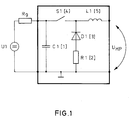
- a pulse power supply 10 is shown in a basic circuit diagram in FIG. This has a voltage source U 1 with associated adaptation and protection electronics, which is referred to and shown as total resistance Rg for the sake of clarity.
- a high-performance capacitor 1 which is parallel to the voltage source U 1 and to which a semiconductor switch 4 in series and a diode 3 as a freewheeling diode and a resistor 2 as a damping resistor are connected in parallel, such as a coil 5 which is connected on the input side between the Semiconductor switch 4 and the diode 3 is integrated and delivers a high-performance voltage U HP on the output side.
- the mechanical structure of the pulse current device 10 is shown in FIG. 2, the voltage source U 1 and the total resistance Rg not being shown in detail, but preferably being incorporated in this structure.
- the pulse current device 10 is constructed in layers.
- the basic component is the high-performance capacitor 1, which consists of one or more winding capacitors 20 is formed, which are introduced and connected in a housing 1.1 (still running).
- the resistor 2 and Diode 3 mechanically attached one after the other and simultaneously electrically connected.
- the resistance 2 is preferably designed as a ceramic disk.
- Via a contact plate 7, made of aluminum or steel, the diode 3 is once with the coil 5 and once with the Coil clearance 5.1 arranged high-performance switch 4 connected.
- the coil 5 is toroidal Designed as a high-current coil.
- the toroidal design ensures that in the coil space 5.1, a magnetic field building up on the coil 5 is zero, since that Magnetic field remains in the winding body of the coil 5. Electromagnetic fields to the outside do not occur due to this design.
- the semiconductor switch 4 is made up of one or more formed in series light-switched thyristors. Between the semiconductor switch 4 and the coil 5 as well as the coil 5 and the contact plate 7, an insulating body 9 is integrated, which preferably has a hat shape that is open on both sides. This is held together layered structure with GRP threaded rods 6.
- the pulse power supply 10 is shown in a top view.
- the external dimensions of the entire pulse power supply 10 are approximately with an electrical energy content of approximately 120 KJ 400 x 400 x 750, as a result of which this pulse power supply can be easily integrated into a vehicle (not shown in more detail).
- a vehicle battery can then act as voltage source U 1 here .
- the structural reduction is primarily due to the special structure of the high-performance capacitor 1 attributed to that of several electrically connected winding capacitors 20 exists.
- the basic structure of the wound capacitor 20 is shown in FIG.
- the individual wrapped foils 21, 22 are with their layers 23, 24 on the upper end face 25 and lower end face 26 connected, which results in the external connections 27, 28 of the wound capacitor 20.
- the foils 21, 22 form the dielectric and have a high dielectric strength.
- the layers 23, 24 form the electrodes. It should be noted that the thinner the electrodes 23, 24 in relation to the foils 21, 22, the higher the electrical results Energy density of the capacitor. Therefore, the foils 21, 22 have a thickness in microns - and Layers 23, 24 have a thickness in the nm range.
- the housing 1.1 is preferably made of synthetic resin, for example, an epoxy resin, cast.
Landscapes
- Generation Of Surge Voltage And Current (AREA)
Abstract
Description
- Figur 1
- einen Prinzipschaltplan einer Pulsstromversorgung
- Figur 2
- einen mechanischen Aufbau der Pulsstromversorgung aus Figur 1
- Figur 2a
- eine Draufsicht auf die Pulsstromversorgung aus Figur 2
- Figur 3
- eine Schnittdarstellung (auszugsweise) eines Wickelkondensators
- Figur 4
- die Zusammenschaltung mehrerer Wickelkondensatoren zu einem Hochleistungskondensator
- U1
- Spannungsquelle
- Rg
- Gesamtwiderstand Anpassung
- 1
- HED-Kondensator
- 1.1
- Gehäuse des Kondensators
- 2
- Dämpfungswiderstand
- 3
- Freilaufdiode
- 4
- Halbleiterschalter
- 5
- Hochstromspule
- 6
- Gewindestab (GFK gerichtet)
- 7
- Kontaktplatte
- 9
- Isolierkörper
- 10
- Pulsstromversorgung
- 20
- Wickelkondensator
- 21
- Folien
- 22
- Folien
- 23
- metallische Schichten
- 24
- metallische Schichten
- 25
- obere Stirnseite
- 26
- untere Stirnseite
- 27
- Anschluß
- 28
- Anschluß
Claims (8)
- Pulsstromversorgung zur Erzeugung von insbesondere Hochleistungspulsen, aufweisend eine Spannungsquelle, die mit einem Energiespeicher verbunden ist, einen Hochleistungsschalter zur Freigabe der gespeicherten Energie sowie einer nachfolgenden Pulsformeinrichtung, dadurch gekennzeichnet, daßals Energiespeicher ein Hochleistungskondensator (1) fungiert, der aus wenigstens einem Wickelkondensator (20) besteht, die bei mehreren elektrisch miteinander verschaltet sind,als Hochleistungsschalter (4) ein Halbleiterschalter eingesetzt wird, der dem Hochleistungskondensator (1) nachgeschaltet ist.
- Pulsstromversorgung nach Anspruchl, dadurch gekennzeichnet, daß der Halbleiterschalter (4) aus ein oder mehreren lichtgeschalteten Thyristoren gebildet wird.
- Pulsstromversorgung nach Anspruch 1 oder 2, dadurch gekennzeichnet, daß die Pulsformeinrichtung aus einer Spule (2) und einer Diode (3) gebildet wird.
- Pulsstromversorgung nach Anspruch 3, dadurch gekennzeichnet, daß die Spule (2) als Toroidspule ausgeführt ist.
- Pulsstromversorgung nach einem oder mehreren der Ansprüche 1 bis 4, dadurch gekennzeichnet, daßdiese schichtartig aufgebaut ist, wobeimehrere Wickelkondensatoren (20) in einem gemeinsamen Gehäuse (1.1) integriert sind, auf dem der Widerstand (2) und die Diode (3) mechanisch befestigt sind,auf der Diode (3) eine Kontaktplatte (7) angeordnet ist, die mit der Spule (5) mechanisch verbunden ist,im Spulenfreiraum (5.1) der Hochleistungsschalter (4) angeordnet ist, der auf der Kontaktplatte (7) befestigt ist, wobeizwischen dem Hochleistungsschalter (4) und der Spule (5) sowie der Spule (5) und der Kontaktplatte (7) ist ein Isolierkörper (9) eingebunden ist.
- Pulsstromversorgung nach Anspruch 5, dadurch gekennzeichnet, daß über die mechanischen Verbindungen die elektrischen Kontakte realisiert werden.
- Pulsstromversorgung nach einem oder mehreren der vorgenannten Ansprüche 1 bis 6, dadurch gekennzeichnet, daßein Wickelkondensator (20) aus gewickelten Polypropylenfolien (21, 22) besteht, die metallisch beschichtet sind, wobei die Polypropylenfolien (21, 22) als Dielektrikum fungieren.
- Pulsstromversorgung nach einem oder mehreren der vorgenannten Ansprüche 1 bis 7, dadurch gekennzeichnet, daß die verbleibenden Hohlräume zwischen den Wickelkondensatoren (20) im Gehäuse (1.1) mit Kunstharz vergossen sind.
Applications Claiming Priority (2)
| Application Number | Priority Date | Filing Date | Title |
|---|---|---|---|
| DE10032639A DE10032639A1 (de) | 2000-07-05 | 2000-07-05 | Kompakte Pulsstromversorgung |
| DE10032639 | 2000-07-05 |
Publications (3)
| Publication Number | Publication Date |
|---|---|
| EP1175009A2 true EP1175009A2 (de) | 2002-01-23 |
| EP1175009A3 EP1175009A3 (de) | 2005-03-30 |
| EP1175009B1 EP1175009B1 (de) | 2012-03-21 |
Family
ID=7647855
Family Applications (1)
| Application Number | Title | Priority Date | Filing Date |
|---|---|---|---|
| EP01114633A Expired - Lifetime EP1175009B1 (de) | 2000-07-05 | 2001-06-19 | Kompakte Pulsstromversorgung |
Country Status (4)
| Country | Link |
|---|---|
| US (1) | US6573618B2 (de) |
| EP (1) | EP1175009B1 (de) |
| KR (1) | KR20020004869A (de) |
| DE (1) | DE10032639A1 (de) |
Families Citing this family (5)
| Publication number | Priority date | Publication date | Assignee | Title |
|---|---|---|---|---|
| DE10032639A1 (de) * | 2000-07-05 | 2002-01-24 | Rheinmetall W & M Gmbh | Kompakte Pulsstromversorgung |
| DE102004058500A1 (de) * | 2004-12-04 | 2006-06-08 | Philips Intellectual Property & Standards Gmbh | Verfahren und Vorrichtung zum Betreiben einer elektrischen Entladevorrichtung |
| TWI439023B (zh) * | 2011-07-13 | 2014-05-21 | Wistron Corp | 低雜訊降壓轉換電路及低雜訊電壓供應總成 |
| WO2014070281A2 (en) * | 2012-08-14 | 2014-05-08 | The Curators Of The University Of Missouri | Optically-triggered linear or avalanche solid state switch for high power applications |
| CN103762883B (zh) * | 2014-02-13 | 2016-06-29 | 郭度厚 | 一种模块式高压大电流脉冲电源装置 |
Family Cites Families (8)
| Publication number | Priority date | Publication date | Assignee | Title |
|---|---|---|---|---|
| DE606241C (de) * | 1932-05-03 | 1934-11-28 | Aeg | Anordnung zur Erzeugung von elektrischen Stossspannungen |
| DE682583C (de) * | 1933-04-11 | 1939-10-18 | Siemens Schuckertwerke Akt Ges | Anordnung zur Erzeugung von Stossspannungen |
| GB942293A (en) * | 1961-06-06 | 1963-11-20 | British Insulated Callenders | Improvements in or relating to electric capacitors |
| DE3623304A1 (de) * | 1986-07-11 | 1988-01-21 | Helmut Arenbeck | Vorrichtung zum erzeugen elektromagnetischer impulse |
| US5559404A (en) * | 1995-06-21 | 1996-09-24 | Aerovox Incorporated | Capacitive pulse forming network |
| US5914974A (en) * | 1997-02-21 | 1999-06-22 | Cymer, Inc. | Method and apparatus for eliminating reflected energy due to stage mismatch in nonlinear magnetic compression modules |
| KR100276020B1 (ko) * | 1998-08-19 | 2001-01-15 | 윤문수 | 비선형 커패시터를 이용한 고압펄스발생 장치 |
| DE10032639A1 (de) * | 2000-07-05 | 2002-01-24 | Rheinmetall W & M Gmbh | Kompakte Pulsstromversorgung |
-
2000
- 2000-07-05 DE DE10032639A patent/DE10032639A1/de not_active Withdrawn
-
2001
- 2001-06-19 EP EP01114633A patent/EP1175009B1/de not_active Expired - Lifetime
- 2001-07-03 US US09/897,432 patent/US6573618B2/en not_active Expired - Lifetime
- 2001-07-04 KR KR1020010039722A patent/KR20020004869A/ko not_active Withdrawn
Also Published As
| Publication number | Publication date |
|---|---|
| US6573618B2 (en) | 2003-06-03 |
| EP1175009B1 (de) | 2012-03-21 |
| DE10032639A1 (de) | 2002-01-24 |
| KR20020004869A (ko) | 2002-01-16 |
| US20020043878A1 (en) | 2002-04-18 |
| EP1175009A3 (de) | 2005-03-30 |
Similar Documents
| Publication | Publication Date | Title |
|---|---|---|
| DE3638748C2 (de) | ||
| DE69423322T2 (de) | Vorrichtung zum Erkennen von Fehlzündung bei einer inneren Brennkraftmaschine ausgerüstet mit doppelendiger Spule und verteilerlosem Zündsystem | |
| DE2932781A1 (de) | Anregungssystem fuer schnelle gepulste entladung | |
| DE2501248A1 (de) | Zuendverteiler fuer verbrennungsmotoren mit einer entstoereinrichtung | |
| DE3411309A1 (de) | Einrichtung zur erzeugung elektrischer pulse | |
| EP1620946B1 (de) | Trigger-/zündeinrichtung in einem aus n stufenkondensatoren bestehenden marx-generator | |
| DE10044867A1 (de) | Explosivstoffgetriebene RF-Strahlenquelle | |
| DE19946786A1 (de) | Pulsgenerator zum Erzeugen eines Spannungspulses und zugehöriges Verfahren | |
| DE69400625T2 (de) | Marx-Generator | |
| DE2635728A1 (de) | Zuendspule | |
| DE3240372A1 (de) | Anregungssystem zur erzeugung einer schnellen, gepulsten hochspannungsentladung, insbesondere zur anregung eines hochleistungslasers | |
| EP1175009B1 (de) | Kompakte Pulsstromversorgung | |
| DE2035368A1 (de) | Induktives und/oder kapazitives elektri sches Bauelement | |
| EP4264037B1 (de) | Zündeinrichtung für eine brennkraftmaschine | |
| EP2532042A1 (de) | Batterie mit induktivem cell-balancing | |
| DE102004034895B4 (de) | Hochspannungsschalter und Verwendung desselben bei einem Mikrowellengenerator | |
| EP0130443B1 (de) | Anregungskreis für ein TE-Hochenergielasersystem | |
| DE3879499T2 (de) | Aufgewickeltes kapazitätsbauelement mit kontrollierter impedanz. | |
| DE19909211B4 (de) | Elektrische Stabzündspule | |
| DE102023101144A1 (de) | Filter zur Unterdrückung von Gleichtaktstörungen und/oder Gegentaktstörungen | |
| DE102018214000A1 (de) | Gleichstrom-Schalteinrichtung und deren Verwendung | |
| DE2745061A1 (de) | Vorrichtung zur unterdrueckung von zuendstoerungen bei motorraedern | |
| EP4239884B1 (de) | Marx-generator mit mehreren zweigen für jeweilige marx-spannungen | |
| DE1942178C3 (de) | Als Kammleitungs- oder Interdigitalfüter ausgebildetes Bandpaßfilter | |
| EP0141202B1 (de) | Schaltungsanordnung zur Funkentstörung |
Legal Events
| Date | Code | Title | Description |
|---|---|---|---|
| PUAI | Public reference made under article 153(3) epc to a published international application that has entered the european phase |
Free format text: ORIGINAL CODE: 0009012 |
|
| AK | Designated contracting states |
Kind code of ref document: A2 Designated state(s): AT BE CH CY DE DK ES FI FR GB GR IE IT LI LU MC NL PT SE TR |
|
| AX | Request for extension of the european patent |
Free format text: AL;LT;LV;MK;RO;SI |
|
| PUAL | Search report despatched |
Free format text: ORIGINAL CODE: 0009013 |
|
| AK | Designated contracting states |
Kind code of ref document: A3 Designated state(s): AT BE CH CY DE DK ES FI FR GB GR IE IT LI LU MC NL PT SE TR |
|
| AX | Request for extension of the european patent |
Extension state: AL LT LV MK RO SI |
|
| 17P | Request for examination filed |
Effective date: 20050908 |
|
| AKX | Designation fees paid |
Designated state(s): DE FR GB NL SE |
|
| RAP1 | Party data changed (applicant data changed or rights of an application transferred) |
Owner name: RHEINMETALL WAFFE MUNITION GMBH |
|
| RAP1 | Party data changed (applicant data changed or rights of an application transferred) |
Owner name: RHEINMETALL WAFFE MUNITION GMBH |
|
| GRAP | Despatch of communication of intention to grant a patent |
Free format text: ORIGINAL CODE: EPIDOSNIGR1 |
|
| GRAS | Grant fee paid |
Free format text: ORIGINAL CODE: EPIDOSNIGR3 |
|
| GRAA | (expected) grant |
Free format text: ORIGINAL CODE: 0009210 |
|
| AK | Designated contracting states |
Kind code of ref document: B1 Designated state(s): DE FR GB NL SE |
|
| REG | Reference to a national code |
Ref country code: GB Ref legal event code: FG4D Free format text: NOT ENGLISH |
|
| REG | Reference to a national code |
Ref country code: DE Ref legal event code: R096 Ref document number: 50116074 Country of ref document: DE Effective date: 20120510 |
|
| REG | Reference to a national code |
Ref country code: SE Ref legal event code: TRGR |
|
| REG | Reference to a national code |
Ref country code: NL Ref legal event code: VDEP Effective date: 20120321 |
|
| PLBE | No opposition filed within time limit |
Free format text: ORIGINAL CODE: 0009261 |
|
| STAA | Information on the status of an ep patent application or granted ep patent |
Free format text: STATUS: NO OPPOSITION FILED WITHIN TIME LIMIT |
|
| PG25 | Lapsed in a contracting state [announced via postgrant information from national office to epo] |
Ref country code: NL Free format text: LAPSE BECAUSE OF FAILURE TO SUBMIT A TRANSLATION OF THE DESCRIPTION OR TO PAY THE FEE WITHIN THE PRESCRIBED TIME-LIMIT Effective date: 20120321 |
|
| 26N | No opposition filed |
Effective date: 20130102 |
|
| GBPC | Gb: european patent ceased through non-payment of renewal fee |
Effective date: 20120621 |
|
| REG | Reference to a national code |
Ref country code: DE Ref legal event code: R097 Ref document number: 50116074 Country of ref document: DE Effective date: 20130102 |
|
| PG25 | Lapsed in a contracting state [announced via postgrant information from national office to epo] |
Ref country code: GB Free format text: LAPSE BECAUSE OF NON-PAYMENT OF DUE FEES Effective date: 20120621 |
|
| REG | Reference to a national code |
Ref country code: FR Ref legal event code: PLFP Year of fee payment: 16 |
|
| PGFP | Annual fee paid to national office [announced via postgrant information from national office to epo] |
Ref country code: DE Payment date: 20160621 Year of fee payment: 16 |
|
| PGFP | Annual fee paid to national office [announced via postgrant information from national office to epo] |
Ref country code: SE Payment date: 20160620 Year of fee payment: 16 Ref country code: FR Payment date: 20160627 Year of fee payment: 16 |
|
| REG | Reference to a national code |
Ref country code: DE Ref legal event code: R119 Ref document number: 50116074 Country of ref document: DE |
|
| REG | Reference to a national code |
Ref country code: SE Ref legal event code: EUG |
|
| PG25 | Lapsed in a contracting state [announced via postgrant information from national office to epo] |
Ref country code: SE Free format text: LAPSE BECAUSE OF NON-PAYMENT OF DUE FEES Effective date: 20170620 |
|
| REG | Reference to a national code |
Ref country code: FR Ref legal event code: ST Effective date: 20180228 |
|
| PG25 | Lapsed in a contracting state [announced via postgrant information from national office to epo] |
Ref country code: DE Free format text: LAPSE BECAUSE OF NON-PAYMENT OF DUE FEES Effective date: 20180103 |
|
| PG25 | Lapsed in a contracting state [announced via postgrant information from national office to epo] |
Ref country code: FR Free format text: LAPSE BECAUSE OF NON-PAYMENT OF DUE FEES Effective date: 20170630 |