EP1174220B1 - Spannelement - Google Patents
Spannelement Download PDFInfo
- Publication number
- EP1174220B1 EP1174220B1 EP01110968A EP01110968A EP1174220B1 EP 1174220 B1 EP1174220 B1 EP 1174220B1 EP 01110968 A EP01110968 A EP 01110968A EP 01110968 A EP01110968 A EP 01110968A EP 1174220 B1 EP1174220 B1 EP 1174220B1
- Authority
- EP
- European Patent Office
- Prior art keywords
- clamping element
- clamping
- plastic moulded
- moulded parts
- parts according
- Prior art date
- Legal status (The legal status is an assumption and is not a legal conclusion. Google has not performed a legal analysis and makes no representation as to the accuracy of the status listed.)
- Expired - Lifetime
Links
Images

Classifications
-
- B—PERFORMING OPERATIONS; TRANSPORTING
- B29—WORKING OF PLASTICS; WORKING OF SUBSTANCES IN A PLASTIC STATE IN GENERAL
- B29C—SHAPING OR JOINING OF PLASTICS; SHAPING OF MATERIAL IN A PLASTIC STATE, NOT OTHERWISE PROVIDED FOR; AFTER-TREATMENT OF THE SHAPED PRODUCTS, e.g. REPAIRING
- B29C65/00—Joining or sealing of preformed parts, e.g. welding of plastics materials; Apparatus therefor
- B29C65/78—Means for handling the parts to be joined, e.g. for making containers or hollow articles, e.g. means for handling sheets, plates, web-like materials, tubular articles, hollow articles or elements to be joined therewith; Means for discharging the joined articles from the joining apparatus
- B29C65/7841—Holding or clamping means for handling purposes
-
- B—PERFORMING OPERATIONS; TRANSPORTING
- B25—HAND TOOLS; PORTABLE POWER-DRIVEN TOOLS; MANIPULATORS
- B25B—TOOLS OR BENCH DEVICES NOT OTHERWISE PROVIDED FOR, FOR FASTENING, CONNECTING, DISENGAGING, OR HOLDING
- B25B5/00—Clamps
- B25B5/06—Arrangements for positively actuating jaws
-
- B—PERFORMING OPERATIONS; TRANSPORTING
- B25—HAND TOOLS; PORTABLE POWER-DRIVEN TOOLS; MANIPULATORS
- B25B—TOOLS OR BENCH DEVICES NOT OTHERWISE PROVIDED FOR, FOR FASTENING, CONNECTING, DISENGAGING, OR HOLDING
- B25B5/00—Clamps
- B25B5/14—Clamps for work of special profile
- B25B5/147—Clamps for work of special profile for pipes
-
- B—PERFORMING OPERATIONS; TRANSPORTING
- B29—WORKING OF PLASTICS; WORKING OF SUBSTANCES IN A PLASTIC STATE IN GENERAL
- B29C—SHAPING OR JOINING OF PLASTICS; SHAPING OF MATERIAL IN A PLASTIC STATE, NOT OTHERWISE PROVIDED FOR; AFTER-TREATMENT OF THE SHAPED PRODUCTS, e.g. REPAIRING
- B29C66/00—General aspects of processes or apparatus for joining preformed parts
- B29C66/50—General aspects of joining tubular articles; General aspects of joining long products, i.e. bars or profiled elements; General aspects of joining single elements to tubular articles, hollow articles or bars; General aspects of joining several hollow-preforms to form hollow or tubular articles
- B29C66/51—Joining tubular articles, profiled elements or bars; Joining single elements to tubular articles, hollow articles or bars; Joining several hollow-preforms to form hollow or tubular articles
- B29C66/52—Joining tubular articles, bars or profiled elements
- B29C66/522—Joining tubular articles
- B29C66/5223—Joining tubular articles for forming corner connections or elbows, e.g. for making V-shaped pieces
-
- B—PERFORMING OPERATIONS; TRANSPORTING
- B29—WORKING OF PLASTICS; WORKING OF SUBSTANCES IN A PLASTIC STATE IN GENERAL
- B29C—SHAPING OR JOINING OF PLASTICS; SHAPING OF MATERIAL IN A PLASTIC STATE, NOT OTHERWISE PROVIDED FOR; AFTER-TREATMENT OF THE SHAPED PRODUCTS, e.g. REPAIRING
- B29C66/00—General aspects of processes or apparatus for joining preformed parts
- B29C66/50—General aspects of joining tubular articles; General aspects of joining long products, i.e. bars or profiled elements; General aspects of joining single elements to tubular articles, hollow articles or bars; General aspects of joining several hollow-preforms to form hollow or tubular articles
- B29C66/51—Joining tubular articles, profiled elements or bars; Joining single elements to tubular articles, hollow articles or bars; Joining several hollow-preforms to form hollow or tubular articles
- B29C66/53—Joining single elements to tubular articles, hollow articles or bars
- B29C66/534—Joining single elements to open ends of tubular or hollow articles or to the ends of bars
-
- Y—GENERAL TAGGING OF NEW TECHNOLOGICAL DEVELOPMENTS; GENERAL TAGGING OF CROSS-SECTIONAL TECHNOLOGIES SPANNING OVER SEVERAL SECTIONS OF THE IPC; TECHNICAL SUBJECTS COVERED BY FORMER USPC CROSS-REFERENCE ART COLLECTIONS [XRACs] AND DIGESTS
- Y10—TECHNICAL SUBJECTS COVERED BY FORMER USPC
- Y10T—TECHNICAL SUBJECTS COVERED BY FORMER US CLASSIFICATION
- Y10T29/00—Metal working
- Y10T29/53—Means to assemble or disassemble
- Y10T29/53961—Means to assemble or disassemble with work-holder for assembly
Definitions
- the invention relates to a clamping element for clamping plastic molded parts during welding, comprising a flange-like fastening part for attachment to a plastic welding device, wherein the clamping element on an inner surface, which is arranged opposite the outer surface of the plastic molding, at least one projection, and wherein the fastening part Has at least a first annular recess for receiving the clamping element.
- plastic moldings such as pipe bends and pipe branches, are used, which are welded together at the site.
- the plastic pipe fittings are aligned axially in a special welding device to each other, clamped and processed at right angles and plan.
- the pipe ends are heated and pressed together axially.
- the plastic pipe fittings are held by clamping systems to the welding device.
- a device for the end-side welding of plastic parts which discloses, inter alia, two generic tensioning devices.
- a clamping device is fixed and the second clamping device is arranged axially displaceable in the welding device.
- the clamping devices are shown as semicircular components which have a relatively large width in the axial direction in comparison with the tube diameter. The large width is necessary to evenly distribute the clamping force on the circumference of the pipe fittings to be welded together and so to keep the pipes well in the desired position during the welding process. It is not described how the clamping force is generated. To enable a good clamping even in tight spaces and with ever smaller fittings and pipe fittings are new Clamping devices desired.
- a clamping element for clamping plastic molded parts during welding comprising a flange-like fastening part for attachment to a plastic welding device, wherein the clamping element on an inner surface, which is arranged opposite the outer surface of the plastic molding, at least one projection, wherein the fastening part at least a first annular recess for receiving the clamping element, and wherein the fastening part has at least one second recess for receiving radially acting on the clamping element spring elements.
- the plastic pipe molding is held securely during welding and as possible without damage in the welding device.
- the inner surface of the annular clamping element is arranged annularly and segmentally, such that the Protrusion encloses the plastic molding during the welding process with evenly distributed clamping force.
- the projection has side surfaces and a clamping surface, wherein the clamping surface is arranged concentrically and segmentally extending to the annular inner surface.
- the plastic pipe molding is prevented from creeping out of the welding device during welding.
- the projections are arranged to extend parallel to each other.
- the projections are arranged in the axial direction of the plastic parts to be welded spaced one behind the other.
- the clamping process on the plastic pipe molding leaves as little visible traces as possible. This is achieved in that the projections have a height of 0.1 to 0.3 mm above the inner surface of the clamping element.
- the highest possible clamping force acts on the plastic pipe moldings during welding.
- the clamping surface are arranged perpendicular to the side surfaces and sharp-edged adjacent to the side surfaces of the projection.
- the clamping surface of the projection has a width B of less than 20% of the width of the inner surface of the clamping element.
- clamping elements are arranged at a distance of less than 25 mm from the welding point of the plastic moldings to be welded.
- plastic pipe moldings can be easily inserted into the welding device and that the Welding device can be easily assembled and operated. This is achieved in that in the plastic welding device for each of the plastic parts to be welded together, two fastening parts and two clamping elements are arranged as semi-circular and mating workpieces on opposite sides of the weld.
- FIG. 1 is a clamping element 1 for clamping plastic pipe moldings shown in a plastic welding device during welding.
- the clamping element 1 is an annular part. Two identical parts each enclose a plastic pipe molding to be welded, which will not be described here.
- a plastic pipe fittings for example, pipe ends, pipe connection areas of valves, valves, pipe branches or arches can be welded together.
- On each side of the weld at least two clamping elements 1 are required to clamp the plastic pipe fittings.
- the clamping elements 1 are designed such that they semicircular the plastic pipe molding enclose. For very large pipe diameters, the clamping elements 1 may be formed in the form of circular segments.
- the tensioning element 1 is essentially an annular disc 2 with a substantially T-shaped profile. On the outside, the disc 2 is bounded by a peripheral edge 3, which is substantially thicker than the rest of the annular disc 2. On the inside of the annular disc 2, the clamping element 1 is bounded by an inner surface 4. A line AA through the clamping element. 1 denotes a sectional area that in the FIGS. 3, 4 and 5 is shown and described.
- FIG. 2 a flange-like fastening part 5 is shown.
- the flange-like fastening part 5 of FIG. 2 has four identical holes 6 through which screws or other fasteners can be introduced. By the screws, the fastening part 5 can be attached to the plastic welding device, or more precisely to the clamping device in the welding device.
- an annular recess 7 is formed, in which the edge 3 of the clamping element 1 of FIG. 1 can be included.
- the fastening part 5 will practically cover the entire clamping element 1, with the exception of the inner area of the pane 2 with the inner surface 4.
- FIG. 1 and FIG. 2 together can also be regarded as an exploded view of clamping element 1 and mounting part 5.
- the flange-like fastening part 5 also has two further recesses 8.
- a spring element 9, here a plate 9 made of spring steel is shown in one of the further recesses 8.
- the spring elements 9 overlap in regions the first recess 7 for receiving the clamping element 1. It is hereby suggested that the spring elements 9 can act radially on the clamping element 1 and thus exerts the clamping element radially inwardly towards the outer surface of the plastic pipe molding a clamping force.
- the Spring elements 9 can also be arranged as leaf spring packets or as helically shaped springs in suitable recesses 8 in the fastening part 5.
- the clamping element 1 in FIG. 1 is divided by a notch 10 in two segments 11a, 11b.
- a spring element 9 is provided in the fastening part 5. If a plurality of spring elements 9 are provided, the clamping element 1 can also be divided into a plurality of segments 11. This ensures that the clamping force distributed as uniformly as possible can be applied to the circumference of the plastic tube.
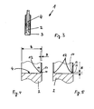
- FIGS. 3, 4 and 5 are cuts along the line AA of FIG. 1 shown enlarged.
- the FIGS. 4 and 5 are larger magnifications of a subregion from the FIG. 3 .
- FIG. 3 is easy to see how the clamping element 1 has a T-shaped cross section in section.
- the shorter bar of the T represents the edge 3 and the longer bar of the T is formed by the annular disc 2 divided into the segments 11a, 11b.
- FIGS. 4 and 5 the part of the clamping element is shown, which is arranged during welding against the outer surface of the plastic molded part.
- the inner surface 4 of the clamping element 1 points in FIG. 4 a projection 12 and in FIG. 5 two projections 12.
- the projections 12 are always arranged to extend parallel to each other and arranged in the axial direction of the plastic pipe moldings to be welded at a certain distance one behind the other. By this axial arrangement of several projections 12 in a row, the plastic pipe is clamped and held at the desired position in the welding device.
- the projections 12 have a clamping surface 13, an inner side surface 14 and an outer side surface 15.
- the projections 12 have a height H of 0.1 to 0.3 mm above the inner surface 4 of the clamping element 1.
- the projection 12 has a width B which less than 20% of the width b of the disc 2 of the clamping element 1 is.
- This width ratio b / B is determined how large the surface pressure on the outer surface of the plastic pipe molding is.
- the clamping surface 13 extends at a right angle to the side surfaces 14,15 and the transition from side surfaces 14, 15 to the clamping surface 13 is sharp-edged, that is, without rounding or chamfer executed.
- the clamping surface 13 is parallel to the inner surface 4 or in the case of a tubular plastic molded part coaxial with the axis of the molded part and coaxial with the inner surface 4 of the clamping element 1.
- This arrangement ensures that the clamping element 1 at most by the height H of the projection 12, the preferably 0.1 to 0.3 mm, is imprinted in the outer surface of the plastic part. This ensures that the plastic parts to be welded together are not unduly deformed at the necessary high contact pressure. For the strength of the plastic part an impression of a few tenths of a mm is allowed. The impression that remains in the outer surface of the plastic part after removing the clamping element 1 and after the welding process will be less deep than the height H of the projection 12th
- the application of a sufficiently high surface pressure is possible. Because the projections 12 of the clamping elements 1 are relatively narrow, the plastic pipe moldings can be clamped very close to the pipe end and very close to the welding point.
- the clamping elements 1 can be arranged, for example, at a distance of less than 25 mm on both sides of the weld. This makes it possible to clamp even very short pieces of pipe and to weld together. Thus, pipelines with branches or fittings can be installed and welded even in very tight spaces.
- the clamping element 1 can be used both for relatively soft and for relatively brittle plastics.
Landscapes
- Engineering & Computer Science (AREA)
- Mechanical Engineering (AREA)
- Lining Or Joining Of Plastics Or The Like (AREA)
- Clamps And Clips (AREA)
- Mutual Connection Of Rods And Tubes (AREA)
- Bidet-Like Cleaning Device And Other Flush Toilet Accessories (AREA)
- Road Signs Or Road Markings (AREA)
Description
- Die Erfindung bezieht sich auf ein Spannelement zum Einspannen von Kunststoffformteilen während des Schweissens, umfassend ein flanschartiges Befestigungsteil zur Befestigung an einer Kunststoffschweissvorrichtung, wobei das Spannelement auf einer Innenfläche, die der Aussenfläche des Kunststoffformteils gegenüberliegend angeordnet ist, mindestens einen Vorsprung aufweist, und wobei das Befestigungsteil mindestens eine erste ringförmige Aussparung zur Aufnahme des Spannelementes aufweist.
- Im Rohrleitungsbau werden zunehmend Kunststoffformteile, wie beispielsweise Rohrbögen und Rohrverzweigungen, eingesetzt, die auf der Baustelle miteinander verschweisst werden. Die Kunststoffrohrformteile werden in einer speziellen Schweissvorrichtung axial zueinander ausgerichtet, eingespannt und rechtwinklig und plan bearbeitet. Die Rohrenden werden aufgeheizt und axial zusammengepresst. Während des Schweissvorganges werden die Kunststoffrohrformteile von Spannsystemen an die Schweissvorrichtung festgehalten.
- Aus der
EP-B-453903 - Aus der
EP 852996 A2 - Ausgehend von diesem Stand der Technik ist es Aufgabe der Erfindung, ein Spannelement zum Einspannen von Kunststoffformteilen während des Schweissens anzugeben, wobei eine möglichst sichere und möglichst platzsparende Einspannung erreicht wird.
- Diese Aufgabe wird gelöst durch ein Spannelement zum Einspannen von Kunststoffformteilen während des Schweissens, umfassend ein flanschartiges Befestigungsteil zur Befestigung an einer Kunststoffschweissvorrichtung, wobei das Spannelement auf einer Innenfläche, die der Aussenfläche des Kunststoffformteils gegenüberliegend angeordnet ist, mindestens einen Vorsprung aufweist, wobei das Befestigungsteil mindestens eine erste ringförmige Aussparung zur Aufnahme des Spannelementes aufweist, und wobei das Befestigungsteil mindestens eine zweite Aussparung zur Aufnahme von radial auf das Spannelement einwirkenden Federelementen aufweist.
- Bevorzugte Weiterbildungen der Erfindung ergeben sich aus den abhängigen Ansprüchen.
- Es ist von Vorteil, dass das Kunststoffrohrformteil während des Schweissens sicher und möglichst ohne Beschädigung in die Schweissvorrichtung festgehalten wird. Dies wird dadurch erreicht, dass die Innenfläche des ringförmigen Spannelementes ringförmig und segmental angeordnet ist, derart, dass der Vorsprung das Kunststoffformteil während dem Schweissvorgang mit gleichmässig verteilter Spannkraft umschliesst. Dies wird auch dadurch erreicht, dass der Vorsprung Seitenflächen und eine Spannfläche aufweist, wobei die Spannfläche konzentrisch und segmental verlaufend zur ringförmigen Innenfläche angeordnet ist.
- Es ist auch von Vorteil, dass das Kunststoffrohrformteil während des Schweissens am Kriechen aus der Schweissvorrichtung gehindert wird. Dies wird dadurch erreicht, dass die Vorsprünge parallel zueinander verlaufend angeordnet sind. Dies wird auch dadurch erreicht, dass die Vorsprünge in axialer Richtung der zu verschweissenden Kunststoffteile beabstandet hintereinander angeordnet sind.
- Es ist auch von Vorteil, dass der Einspannvorgang am Kunststoffrohrformteil möglichst wenig sichtbare Spuren hinterlässt. Dies wird dadurch erreicht, dass die Vorsprünge eine Höhe von 0,1 bis 0,3 mm über der Innenfläche des Spannelementes aufweisen.
- Es ist weiter von Vorteil, dass während des Schweissens eine möglichst hohe Spannkraft auf die Kunststoffrohrformteile wirkt. Dies wird dadurch erreicht, dass die Spannfläche rechtwinklig zu den Seitenflächen und scharfkantig angrenzend an den Seitenflächen des Vorsprungs angeordnet sind. Dies wird auch dadurch erreicht, dass die Spannfläche des Vorsprungs eine Breite B von weniger als 20 % der Breite der Innenfläche des Spannelementes aufweist.
- Es ist weiter von Vorteil, dass auch verhältnismässig kurze Rohrformteile zuverlässig mit einander verschweisst werden können. Dies wird dadurch erreicht, dass die Spannelemente in einem Abstand von weniger als 25 mm von der Schweissstelle der zu verschweissenden Kunststoffformteile angeordnet sind.
- Es ist auch von Vorteil, dass die Kunststoffrohrformteile einfach in die Schweissvorrichtung eingebracht werden können und dass die Schweissvorrichtung einfach zusammengesetzt und bedient werden kann. Dies wird dadurch erreicht, dass in der Kunststoffschweissvorrichtung zu jedem der miteinander zu verschweissenden Kunststoffteile jeweils zwei Befestigungsteile und zwei Spannelemente als halbkreisförmigen und zueinander passenden Werkstücke auf gegenüberliegenden Seiten der Schweissstelle angeordnet sind.
- Ein Ausführungsbeispiel der Erfindung wird anhand der Figuren beschrieben. Es zeigen:
-
Figur 1 eine Sicht auf ein erfindungsgemässes Spannelement, -
Figur 2 eine Sicht auf ein flanschartiges Befestigungsteil zur Aufnahme des Spannelementes ausFigur 1 , -
Figur 3 einen etwas vergrösserten Schnitt durch das Spannelement vonFigur 1 , -
Figur 4 eine weitere Vergrösserung aus einem Teilbereich des Spannelementes vonFigur 3 und -
Figur 5 ein zweites Ausführungsbeispiel des Spannelementes vonFigur 4 . - In
Figur 1 ist ein Spannelement 1 zum Einspannen von Kunststoffrohrformteilen in einer Kunststoffschweissvorrichtung während des Schweissens dargestellt. Das Spannelement 1 ist ein ringförmiges Teil. Zwei identische Teile umschliessen jeweils ein zu verschweissendes Kunststoffrohrformteil, das hier nicht näher beschrieben wird. Als Kunststoffrohrformteile können beispielsweise Rohrleitungsenden, Rohrleitungsanschlussbereiche von Armaturen, Ventilen, Rohrleitungsverzweigungen oder Bögen miteinander verschweisst werden. Auf jeder Seite der Schweissstelle sind jeweils mindestens zwei Spannelemente 1 erforderlich um die Kunststoffrohrformteile einzuspannen. Die Spannelemente 1 sind derart ausgebildet, das sie das Kunststoffrohrformteil halbkreisförmig umschliessen. Bei sehr grossen Rohrleitungsdurchmessern können die Spannelemente 1 auch in Form von Kreissegmenten ausgebildet sein. - Das Spannelement 1 ist im Wesentlichen eine ringförmige Scheibe 2 mit einem im wesentlichen T-förmigen Profil. Auf der Aussenseite wird die Scheibe 2 begrenzt von einem umlaufenden Rand 3, der wesentlich dicker ist als der Rest der ringförmigen Scheibe 2. Auf der Innenseite der ringförmige Scheibe 2 wird das Spannelement 1 begrenzt von einer Innenfläche 4. Eine Linie AA durch das Spannelement 1 bezeichnet eine Schnittfläche, die in den
Figuren 3, 4 und 5 dargestellt und beschrieben ist. - In
Figur 2 ist ein flanschartiges Befestigungsteil 5 dargestellt. Das flanschartige Befestigungssteil 5 vonFigur 2 weist vier identische Bohrungen 6 auf, durch die Schrauben oder andere Befestigungsmittel eingebracht werden können. Durch die Schrauben kann das Befestigungsteil 5 an die Kunststoffschweissvorrichtung, oder genauer gesagt an die Spannvorrichtung in der Schweissvorrichtung, befestigt werden. Im Befestigungsteil 5 ist eine ringförmige Aussparung 7 ausgebildet, in die der Rand 3 des Spannelementes 1 vonFigur 1 aufgenommen werden kann. Wenn das Spannelement 1 im Befestigungsteil 5 aufgenommen ist, wird das Befestigungsteil 5 praktisch das gesamte Spannelement 1 überdecken, mit Ausnahme des inneren Bereichs des Scheibe 2 mit der Innenfläche 4.Figur 1 und Figur 2 zusammen können auch als eine Explosionsdarstellung von Spannelement 1 und Befestigungsteil 5 aufgefasst werden. - Das flanschartige Befestigungsteil 5 weist auch zwei weitere Aussparungen 8 auf. In einer der weiteren Aussparungen 8 ist ein Federelement 9, hier eine Platte 9 aus Federstahl dargestellt. Die Federelemente 9 überschneiden bereichsweise die erste Aussparung 7 zur Aufnahme des Spannelementes 1. Hiermit wird angedeutet, dass die Federelemente 9 radial auf das Spannelement 1 einwirken können und somit das Spannelement radial nach innen in Richtung auf die Aussenfläche des Kunststoffrohrformteiles eine Spannkraft ausübt. Die Federelemente 9 können auch als Blattfederpakete oder als schraubenförmig ausgebildete Federn in dazu geeigneten Aussparungen 8 im Befestigungsteil 5 angeordnet werden. Das Spannelement 1 in
Figur 1 ist durch eine Kerbe 10 in zwei Segmenten 11a, 11b aufgeteilt. Zu jedem Segment 11a, 11b ist im Befestigungsteil 5 ein Federelement 9 vorgesehen. Wenn mehrere Federelemente 9 vorgesehen sind, kann auch das Spannelement 1 in mehreren Segmenten 11 aufgeteilt sein. Hiermit wird erreicht, dass die Spannkraft möglichst gleichmässig verteilt am Umfang des Kunststoffrohres aufgebracht werden kann. - In den
Figuren 3, 4 und 5 sind Schnitte entlang der Linie AA vonFigur 1 vergrössert dargestellt. DieFiguren 4 und 5 sind stärkere Vergrösserungen von einem Teilbereich aus derFigur 3 . InFigur 3 ist gut ersichtlich, wie das Spannelement 1 im Schnitt einen T-förmigen Querschnitt aufweist. Der kürzere Balken des T stellt der Rand 3 dar und der längere Balken des T wird durch die ringförmige Scheibe 2, aufgeteilt in den Segmenten 11a, 11b gebildet. - In
Figuren 4 und 5 ist der Teil des Spannelementes dargestellt, der während des Schweissens gegenüber der Aussenfläche des Kunststoffformteiles angeordnet ist. Die Innenfläche 4 des Spannelementes 1 weist inFigur 4 einen Vorsprung 12 und inFigur 5 zwei Vorsprünge 12 auf. Es sind auch Ausführungen mit mehreren Vorsprüngen 12 denkbar. Die Vorsprünge 12 sind jedoch immer parallel zueinander verlaufend angeordnet und in axialer Richtung der zu verschweissenden Kunststoffrohrformteile in einem gewissen Abstand hintereinander angeordnet. Durch diese axiale Anordnung von mehreren Vorsprüngen 12 hintereinander wird das Kunststoffrohr eingespannt und an der gewünschten Position in der Schweissvorrichtung gehalten. Die Vorsprünge 12 weisen eine Spannfläche 13, eine innere Seitenfläche 14 und eine äussere Seitenfläche 15 auf. Die Vorsprünge 12 weisen eine Höhe H von 0,1 bis 0,3 mm über der Innenfläche 4 des Spannelementes 1 auf. - In
Figur 4 ist auch ersichtlich, wie der Vorsprung 12 eine Breite B aufweist, die weniger als 20% der Breite b der Scheibe 2 des Spannelementes 1 beträgt. Durch dieses Breitenverhältnis b/B wird bestimmt, wie gross der Flächendruck auf der Aussenfläche des Kunststoffrohrformteiles ist. Die Spannfläche 13 verläuft in einem rechten Winkel zu den Seitenflächen 14,15 und der Übergang von Seitenflachen 14, 15 zur Spannfläche 13 ist scharfkantig, das heisst ohne Rundung oder Fasung, ausgeführt. Die Spannfläche 13 verläuft parallel zur Innenfläche 4 oder im Falle eines rohrförmigen Kunststoffformteiles koaxial mit der Achse des Formteiles und koaxial mit der Innenfläche 4 des Spannelementes 1. Durch diese Anordnung wird sichergestellt, dass das Spannelement 1 höchstens um die Höhe H des Vorsprungs 12, die vorzugsweise 0,1 bis 0,3 mm beträgt, in die Aussenfläche des Kunststoffteiles eingedruckt wird. Dadurch wird erreicht, dass die miteinander zu verschweissenden Kunststoffteile bei dem notwendigen hohen Anpressdruck nicht unzulässig verformt werden. Für die Festigkeit des Kunststoffteiles ist ein Eindruck von wenigen Zehntel mm zulässig. Der Eindruck, der in der Aussenfläche des Kunststoffteiles nach dem Entfernen des Spannelementes 1 und nach dem Schweissvorgang zurückbleibt, wird weniger tief sein als die Höhe H des Vorsprunges 12. - Durch das T-förmige Profil des Spannelementes 1, zusammen mit dem Breitenverhältnis b/B wird die Aufbringung eines ausreichend hohen Flächendruckes möglich. Weil die Vorsprünge 12 der Spannelemente 1 verhältnismässig schmal sind, können die Kunststoffrohrformteile sehr nahe beim Rohrende und sehr nah bei der Schweissstelle eingespannt werden. Die Spannelemente 1 können beispielsweise auf einem Abstand von weniger als 25 mm auf beiden Seiten der Schweissstelle angeordnet werden. Hierdurch wird es möglich auch sehr kurze Rohrstücke einzuspannen und miteinander zu verschweissen. Somit können auch bei sehr engen Platzverhältnissen Rohrleitungen mit Verzweigungen oder Armaturen eingebaut und verschweisst werden. Das Spannelement 1 kann sowohl für verhältnismässig weiche als auch für verhältnismässig spröde Kunststoffe verwendet werden.
Claims (11)
- Spannelement (1) zum Einspannen von Kunststoffformteilen während des Schweissens, umfassend ein flanschartiges Befestigungsteil (5) zur Befestigung an einer Kunststoffschweissvorrichtung, wobei das Spannelement (1) auf einer Innenfläche (4), die der Aussenfläche des Kunststoffformteils gegenüberliegend angeordnet ist, mindestens einen Vorsprung (12) aufweist, und wobei das Befestigungsteil (5) mindestens eine erste ringförmige Aussparung (7) zur Aufnahme des Spannelementes (1) aufweist, dadurch gekennzeichnet, dass das Befestigungsteil (5) mindestens eine zweite Aussparung (8) zur Aufnahme von radial auf das Spannelement (1) einwirkenden Federelementen (9) aufweist.
- Spannelement zum Einspannen von Kunststoffformteilen nach dem Anspruch 1, dadurch gekennzeichnet, dass die Innenfläche (4) des ringförmigen Spannelementes (1) sich koaxial mit dem Kunststoffformteil erstreckt und segmental angeordnet ist, derart, dass der Vorsprung (12) das Kunststoffformteil während dem Schweissvorgang mit gleichmässig verteilter Spannkraft umschliesst.
- Spannelement zum Einspannen von Kunststoffformteilen nach einem der Ansprüche 1 oder 2, dadurch gekennzeichnet, dass der Vorsprung (12) Seitenflächen (14,15) und eine Spannfläche (13) aufweist, wobei die Spannfläche konzentrisch verlaufend zur sich axial erstreckenden Innenfläche (4) angeordnet ist.
- Spannelement zum Einspannen von Kunststoffformteilen nach einem der Ansprüche 1 bis 3, dadurch gekennzeichnet, dass die Vorsprünge (12) parallel zueinander verlaufend angeordnet sind.
- Spannelement zum Einspannen von Kunststoffformteilen nach einem der Ansprüche 1 bis 4, dadurch gekennzeichnet, dass die Vorsprünge (12) in axialer Richtung der zu verschweissenden Kunststoffteile beabstandet hintereinander angeordnet sind.
- Spannelement zum Einspannen von Kunststoffformteilen nach einem der Ansprüche 1 bis 5, dadurch gekennzeichnet, dass die Vorsprünge (12) eine Höhe H von 0,1 bis 0,3 mm über der Innenfläche (4) des Spannelementes (1) aufweisen.
- Spannelement zum Einspannen von Kunststoffformteilen nach einem der Ansprüche 1 bis 6, dadurch gekennzeichnet, dass die Spannfläche (13) des Vorsprungs (12) eine Breite B von weniger als 20 % der Breite b der Innenfläche (4) des Spannelementes (1) aufweist.
- Spannelement zum Einspannen von Kunststoffformteilen nach einem der Ansprüche 1 bis 7, dadurch gekennzeichnet, dass die Spannfläche (13) rechtwinklig zu den Seitenflächen (14,15) und scharfkantig angrenzend an den Seitenflächen des Vorsprungs (12) angeordnet sind.
- Spannelement zum Einspannen von Kunststoffformteilen nach einem der Ansprüche 1 bis 8, dadurch gekennzeichnet, dass in der Kunststoffschweissvorrichtung zu jedem der miteinander zu verschweissenden Kunststoffteile jeweils zwei Befestigungsteile (5) und zwei Spannelemente (1) als halbkreisförmigen und zueinander passenden Werkstücke auf gegenüberliegenden Seiten der Schweissstelle angeordnet sind.
- Spannelement zum Einspannen von Kunststoffformteilen nach einem der Ansprüche 1 bis 9, dadurch gekennzeichnet, dass die Spannelemente (1) in einem Abstand von weniger als 25 mm von der Schweissstelle der zu verschweissenden Kunststoffformteile angeordnet sind.
- Spannelement zum Einspannen von Kunststoffformteilen nach einem der Ansprüche 1 bis 10, dadurch gekennzeichnet, dass die Kunststoffformteile Kunststoffrohrformteile sind.
Applications Claiming Priority (2)
| Application Number | Priority Date | Filing Date | Title |
|---|---|---|---|
| DE10035093A DE10035093A1 (de) | 2000-07-17 | 2000-07-17 | Spannelement |
| DE10035093 | 2000-07-17 |
Publications (3)
| Publication Number | Publication Date |
|---|---|
| EP1174220A2 EP1174220A2 (de) | 2002-01-23 |
| EP1174220A3 EP1174220A3 (de) | 2002-04-24 |
| EP1174220B1 true EP1174220B1 (de) | 2010-07-07 |
Family
ID=7649454
Family Applications (1)
| Application Number | Title | Priority Date | Filing Date |
|---|---|---|---|
| EP01110968A Expired - Lifetime EP1174220B1 (de) | 2000-07-17 | 2001-05-07 | Spannelement |
Country Status (5)
| Country | Link |
|---|---|
| US (1) | US6510598B2 (de) |
| EP (1) | EP1174220B1 (de) |
| JP (1) | JP2002137303A (de) |
| AT (1) | ATE473069T1 (de) |
| DE (2) | DE10035093A1 (de) |
Family Cites Families (14)
| Publication number | Priority date | Publication date | Assignee | Title |
|---|---|---|---|---|
| DE2020625A1 (de) * | 1970-04-28 | 1971-12-09 | Atlas Copco Ab | Vorrichtung zum reibschluessigen Einspannen von vorzugsweise zylindrischen Werkstuecken |
| US3805646A (en) * | 1972-11-14 | 1974-04-23 | J Knight | Chain wrench |
| JPS6028579Y2 (ja) * | 1979-08-04 | 1985-08-30 | 大阪瓦斯株式会社 | 融着機 |
| JPS5935013U (ja) * | 1982-08-27 | 1984-03-05 | 三菱電線工業株式会社 | プラスチツクパイプ接続装置 |
| JPS6051026U (ja) * | 1983-09-16 | 1985-04-10 | 三菱樹脂株式会社 | バツト融着機 |
| FR2619038A1 (fr) * | 1987-08-07 | 1989-02-10 | Automatisme Robotique Applique | Pinces, equipant des convoyeurs de machines de cablage automatiques, destinees a tenir un ou plusieurs fils conducteurs |
| US4874156A (en) * | 1988-01-07 | 1989-10-17 | Abe Goldzweig | Hand or foot manipulated self clamping device |
| DE4013471A1 (de) * | 1990-04-27 | 1991-10-31 | Fischer Ag Georg | Einrichtung zum stirnseitigen verschweissen von kunststoffteilen |
| US5241157A (en) | 1990-04-27 | 1993-08-31 | Georg Fischer Ag | Arrangement for butt-welding plastic material components |
| DE4121380A1 (de) * | 1991-06-28 | 1993-01-07 | Immanuel Jeschke | Einspannvorrichtung fuer mit einer schweissmuffe zu verschweissende kunststoffrohre |
| US5312094A (en) * | 1993-01-21 | 1994-05-17 | Zera Robert D | Vacuum clamp |
| DE9319410U1 (de) * | 1993-12-17 | 1995-04-13 | Robert Bosch Gmbh, 70469 Stuttgart | Vorrichtung zum Halten von Rohren bei axial auftretenden Kräften |
| US5919335A (en) * | 1996-08-01 | 1999-07-06 | Tdw Delaware, Inc. | Facer and hand held tool for joining small diameter plastic pipe |
| US5770006A (en) | 1997-01-13 | 1998-06-23 | Tdw Delaware, Inc. | Butt fusion machine for manufacturing full size segemented pipe turns |
-
2000
- 2000-07-17 DE DE10035093A patent/DE10035093A1/de not_active Withdrawn
-
2001
- 2001-05-07 DE DE50115543T patent/DE50115543D1/de not_active Expired - Lifetime
- 2001-05-07 AT AT01110968T patent/ATE473069T1/de active
- 2001-05-07 EP EP01110968A patent/EP1174220B1/de not_active Expired - Lifetime
- 2001-06-20 US US09/885,664 patent/US6510598B2/en not_active Expired - Lifetime
- 2001-07-17 JP JP2001216370A patent/JP2002137303A/ja active Pending
Also Published As
| Publication number | Publication date |
|---|---|
| DE10035093A1 (de) | 2002-01-31 |
| US20020004976A1 (en) | 2002-01-17 |
| JP2002137303A (ja) | 2002-05-14 |
| EP1174220A3 (de) | 2002-04-24 |
| ATE473069T1 (de) | 2010-07-15 |
| US6510598B2 (en) | 2003-01-28 |
| DE50115543D1 (de) | 2010-08-19 |
| EP1174220A2 (de) | 2002-01-23 |
Similar Documents
| Publication | Publication Date | Title |
|---|---|---|
| EP1600679B1 (de) | Verbindungsanordnung aus Kunststoff zum Festlegen eines Schlauches | |
| EP1912008B1 (de) | Schlauchschelle | |
| DE102017105505A1 (de) | Fitting zum Verbinden mit mindestens einem Rohr und Verfahren zum Herstellen einer Verbindung | |
| EP3308065B1 (de) | Schelle | |
| DE102010052782A1 (de) | Fahrzeuginsassenrückhaltesystem für ein Fahrzeug und Dichtungselement | |
| DE102014212441A1 (de) | Gasauslassventil für ein hydraulisches Ausrücksystem einer Kupplung | |
| DE69836553T2 (de) | Kuppelstück für rohre | |
| WO2019211053A1 (de) | Schelle | |
| DE202020102046U1 (de) | Rohrleitungsverbindungsstruktur | |
| EP3515790B1 (de) | Manteleinheit für eine verstellbare lenksäule eines kraftfahrzeugs | |
| DE20300918U1 (de) | Pressverbindungsanordnung | |
| DE102007037757A1 (de) | Locheinheit für ein Werkzeug zum Bearbeiten von Blechbauteilen | |
| EP3775658A1 (de) | Anschlussvorrichtung für medienleitungen | |
| DE10236550A1 (de) | Haltevorrichtung für ein Leitungsstrang-Schuhelement | |
| EP1775507B1 (de) | Fitting für Rohrleitungen | |
| EP1979664B1 (de) | Spannschelle für hochdruck-schläuche | |
| EP1174220A2 (de) | Spannelement | |
| DE9410500U1 (de) | Fluidisch betätigbares. leistenartiges Klemmwerkzeug | |
| DE102007028964A1 (de) | Baugruppe eines Fahrzeuggetriebes und Vorrichtung mit einem Verriegelungsstift zum Verriegeln eines Getriebeteils der Baugruppe | |
| EP1767285B1 (de) | Biegewerkzeug für Hydraulik-Bogenarmaturen | |
| DE202006006746U1 (de) | Verbindungseinheit mit Schelle | |
| EP4502400B1 (de) | Vorrichtung zur einstellung der vorspannkraft einer feder | |
| EP1703192A1 (de) | Bajonettverbindung | |
| DE102017129324B4 (de) | Anschlussvorrichtung für Medienleitungen und Verfahren zur Montage einer Anschlussvorrichtung | |
| DE202005016424U1 (de) | Haltering zum Verbinden einer Presshülse mit einem Fitting |
Legal Events
| Date | Code | Title | Description |
|---|---|---|---|
| PUAI | Public reference made under article 153(3) epc to a published international application that has entered the european phase |
Free format text: ORIGINAL CODE: 0009012 |
|
| AK | Designated contracting states |
Kind code of ref document: A2 Designated state(s): AT BE CH CY DE DK ES FI FR GB GR IE IT LI LU MC NL PT SE TR |
|
| AX | Request for extension of the european patent |
Free format text: AL;LT;LV;MK;RO;SI |
|
| PUAL | Search report despatched |
Free format text: ORIGINAL CODE: 0009013 |
|
| AK | Designated contracting states |
Kind code of ref document: A3 Designated state(s): AT BE CH CY DE DK ES FI FR GB GR IE IT LI LU MC NL PT SE TR |
|
| AX | Request for extension of the european patent |
Free format text: AL;LT;LV;MK;RO;SI |
|
| 17P | Request for examination filed |
Effective date: 20020508 |
|
| AKX | Designation fees paid |
Free format text: AT BE CH CY DE DK ES FI FR GB GR IE IT LI LU MC NL PT SE TR |
|
| 17Q | First examination report despatched |
Effective date: 20080111 |
|
| GRAP | Despatch of communication of intention to grant a patent |
Free format text: ORIGINAL CODE: EPIDOSNIGR1 |
|
| GRAS | Grant fee paid |
Free format text: ORIGINAL CODE: EPIDOSNIGR3 |
|
| GRAA | (expected) grant |
Free format text: ORIGINAL CODE: 0009210 |
|
| AK | Designated contracting states |
Kind code of ref document: B1 Designated state(s): AT BE CH CY DE DK ES FI FR GB GR IE IT LI LU MC NL PT SE TR |
|
| REG | Reference to a national code |
Ref country code: GB Ref legal event code: FG4D Free format text: NOT ENGLISH |
|
| REG | Reference to a national code |
Ref country code: CH Ref legal event code: EP |
|
| REG | Reference to a national code |
Ref country code: IE Ref legal event code: FG4D |
|
| REF | Corresponds to: |
Ref document number: 50115543 Country of ref document: DE Date of ref document: 20100819 Kind code of ref document: P |
|
| REG | Reference to a national code |
Ref country code: NL Ref legal event code: VDEP Effective date: 20100707 |
|
| PG25 | Lapsed in a contracting state [announced via postgrant information from national office to epo] |
Ref country code: NL Free format text: LAPSE BECAUSE OF FAILURE TO SUBMIT A TRANSLATION OF THE DESCRIPTION OR TO PAY THE FEE WITHIN THE PRESCRIBED TIME-LIMIT Effective date: 20100707 Ref country code: FI Free format text: LAPSE BECAUSE OF FAILURE TO SUBMIT A TRANSLATION OF THE DESCRIPTION OR TO PAY THE FEE WITHIN THE PRESCRIBED TIME-LIMIT Effective date: 20100707 |
|
| REG | Reference to a national code |
Ref country code: IE Ref legal event code: FD4D |
|
| PG25 | Lapsed in a contracting state [announced via postgrant information from national office to epo] |
Ref country code: PT Free format text: LAPSE BECAUSE OF FAILURE TO SUBMIT A TRANSLATION OF THE DESCRIPTION OR TO PAY THE FEE WITHIN THE PRESCRIBED TIME-LIMIT Effective date: 20101108 Ref country code: CY Free format text: LAPSE BECAUSE OF FAILURE TO SUBMIT A TRANSLATION OF THE DESCRIPTION OR TO PAY THE FEE WITHIN THE PRESCRIBED TIME-LIMIT Effective date: 20100707 |
|
| PG25 | Lapsed in a contracting state [announced via postgrant information from national office to epo] |
Ref country code: GR Free format text: LAPSE BECAUSE OF FAILURE TO SUBMIT A TRANSLATION OF THE DESCRIPTION OR TO PAY THE FEE WITHIN THE PRESCRIBED TIME-LIMIT Effective date: 20101008 Ref country code: SE Free format text: LAPSE BECAUSE OF FAILURE TO SUBMIT A TRANSLATION OF THE DESCRIPTION OR TO PAY THE FEE WITHIN THE PRESCRIBED TIME-LIMIT Effective date: 20100707 |
|
| PG25 | Lapsed in a contracting state [announced via postgrant information from national office to epo] |
Ref country code: DK Free format text: LAPSE BECAUSE OF FAILURE TO SUBMIT A TRANSLATION OF THE DESCRIPTION OR TO PAY THE FEE WITHIN THE PRESCRIBED TIME-LIMIT Effective date: 20100707 Ref country code: IE Free format text: LAPSE BECAUSE OF FAILURE TO SUBMIT A TRANSLATION OF THE DESCRIPTION OR TO PAY THE FEE WITHIN THE PRESCRIBED TIME-LIMIT Effective date: 20100707 |
|
| PLBE | No opposition filed within time limit |
Free format text: ORIGINAL CODE: 0009261 |
|
| STAA | Information on the status of an ep patent application or granted ep patent |
Free format text: STATUS: NO OPPOSITION FILED WITHIN TIME LIMIT |
|
| PG25 | Lapsed in a contracting state [announced via postgrant information from national office to epo] |
Ref country code: IT Free format text: LAPSE BECAUSE OF FAILURE TO SUBMIT A TRANSLATION OF THE DESCRIPTION OR TO PAY THE FEE WITHIN THE PRESCRIBED TIME-LIMIT Effective date: 20100707 |
|
| 26N | No opposition filed |
Effective date: 20110408 |
|
| PG25 | Lapsed in a contracting state [announced via postgrant information from national office to epo] |
Ref country code: ES Free format text: LAPSE BECAUSE OF FAILURE TO SUBMIT A TRANSLATION OF THE DESCRIPTION OR TO PAY THE FEE WITHIN THE PRESCRIBED TIME-LIMIT Effective date: 20101018 |
|
| REG | Reference to a national code |
Ref country code: DE Ref legal event code: R097 Ref document number: 50115543 Country of ref document: DE Effective date: 20110408 |
|
| BERE | Be: lapsed |
Owner name: GEORG FISCHER ROHRLEITUNGSSYSTEME A.G. Effective date: 20110531 |
|
| PG25 | Lapsed in a contracting state [announced via postgrant information from national office to epo] |
Ref country code: MC Free format text: LAPSE BECAUSE OF NON-PAYMENT OF DUE FEES Effective date: 20110531 |
|
| REG | Reference to a national code |
Ref country code: CH Ref legal event code: PL |
|
| GBPC | Gb: european patent ceased through non-payment of renewal fee |
Effective date: 20110507 |
|
| PG25 | Lapsed in a contracting state [announced via postgrant information from national office to epo] |
Ref country code: LI Free format text: LAPSE BECAUSE OF NON-PAYMENT OF DUE FEES Effective date: 20110531 Ref country code: CH Free format text: LAPSE BECAUSE OF NON-PAYMENT OF DUE FEES Effective date: 20110531 |
|
| REG | Reference to a national code |
Ref country code: FR Ref legal event code: ST Effective date: 20120131 |
|
| PG25 | Lapsed in a contracting state [announced via postgrant information from national office to epo] |
Ref country code: BE Free format text: LAPSE BECAUSE OF NON-PAYMENT OF DUE FEES Effective date: 20110531 |
|
| PG25 | Lapsed in a contracting state [announced via postgrant information from national office to epo] |
Ref country code: FR Free format text: LAPSE BECAUSE OF NON-PAYMENT OF DUE FEES Effective date: 20110531 |
|
| PG25 | Lapsed in a contracting state [announced via postgrant information from national office to epo] |
Ref country code: GB Free format text: LAPSE BECAUSE OF NON-PAYMENT OF DUE FEES Effective date: 20110507 |
|
| PG25 | Lapsed in a contracting state [announced via postgrant information from national office to epo] |
Ref country code: LU Free format text: LAPSE BECAUSE OF NON-PAYMENT OF DUE FEES Effective date: 20110507 |
|
| PG25 | Lapsed in a contracting state [announced via postgrant information from national office to epo] |
Ref country code: TR Free format text: LAPSE BECAUSE OF FAILURE TO SUBMIT A TRANSLATION OF THE DESCRIPTION OR TO PAY THE FEE WITHIN THE PRESCRIBED TIME-LIMIT Effective date: 20100707 |
|
| PGFP | Annual fee paid to national office [announced via postgrant information from national office to epo] |
Ref country code: DE Payment date: 20170523 Year of fee payment: 17 |
|
| PGFP | Annual fee paid to national office [announced via postgrant information from national office to epo] |
Ref country code: AT Payment date: 20170522 Year of fee payment: 17 |
|
| REG | Reference to a national code |
Ref country code: DE Ref legal event code: R119 Ref document number: 50115543 Country of ref document: DE |
|
| REG | Reference to a national code |
Ref country code: AT Ref legal event code: MM01 Ref document number: 473069 Country of ref document: AT Kind code of ref document: T Effective date: 20180507 |
|
| PG25 | Lapsed in a contracting state [announced via postgrant information from national office to epo] |
Ref country code: AT Free format text: LAPSE BECAUSE OF NON-PAYMENT OF DUE FEES Effective date: 20180507 |
|
| PG25 | Lapsed in a contracting state [announced via postgrant information from national office to epo] |
Ref country code: DE Free format text: LAPSE BECAUSE OF NON-PAYMENT OF DUE FEES Effective date: 20181201 |