EP1173664B1 - Kühlluftsystem - Google Patents
Kühlluftsystem Download PDFInfo
- Publication number
- EP1173664B1 EP1173664B1 EP01915036A EP01915036A EP1173664B1 EP 1173664 B1 EP1173664 B1 EP 1173664B1 EP 01915036 A EP01915036 A EP 01915036A EP 01915036 A EP01915036 A EP 01915036A EP 1173664 B1 EP1173664 B1 EP 1173664B1
- Authority
- EP
- European Patent Office
- Prior art keywords
- cooling air
- flow
- heat exchanger
- area
- compressor
- Prior art date
- Legal status (The legal status is an assumption and is not a legal conclusion. Google has not performed a legal analysis and makes no representation as to the accuracy of the status listed.)
- Expired - Lifetime
Links
Images

Classifications
-
- F—MECHANICAL ENGINEERING; LIGHTING; HEATING; WEAPONS; BLASTING
- F01—MACHINES OR ENGINES IN GENERAL; ENGINE PLANTS IN GENERAL; STEAM ENGINES
- F01D—NON-POSITIVE DISPLACEMENT MACHINES OR ENGINES, e.g. STEAM TURBINES
- F01D25/00—Component parts, details, or accessories, not provided for in, or of interest apart from, other groups
- F01D25/08—Cooling; Heating; Heat-insulation
- F01D25/12—Cooling
-
- F—MECHANICAL ENGINEERING; LIGHTING; HEATING; WEAPONS; BLASTING
- F01—MACHINES OR ENGINES IN GENERAL; ENGINE PLANTS IN GENERAL; STEAM ENGINES
- F01D—NON-POSITIVE DISPLACEMENT MACHINES OR ENGINES, e.g. STEAM TURBINES
- F01D5/00—Blades; Blade-carrying members; Heating, heat-insulating, cooling or antivibration means on the blades or the members
- F01D5/12—Blades
- F01D5/14—Form or construction
- F01D5/18—Hollow blades, i.e. blades with cooling or heating channels or cavities; Heating, heat-insulating or cooling means on blades
- F01D5/187—Convection cooling
-
- F—MECHANICAL ENGINEERING; LIGHTING; HEATING; WEAPONS; BLASTING
- F01—MACHINES OR ENGINES IN GENERAL; ENGINE PLANTS IN GENERAL; STEAM ENGINES
- F01D—NON-POSITIVE DISPLACEMENT MACHINES OR ENGINES, e.g. STEAM TURBINES
- F01D9/00—Stators
- F01D9/06—Fluid supply conduits to nozzles or the like
- F01D9/065—Fluid supply or removal conduits traversing the working fluid flow, e.g. for lubrication-, cooling-, or sealing fluids
-
- F—MECHANICAL ENGINEERING; LIGHTING; HEATING; WEAPONS; BLASTING
- F02—COMBUSTION ENGINES; HOT-GAS OR COMBUSTION-PRODUCT ENGINE PLANTS
- F02C—GAS-TURBINE PLANTS; AIR INTAKES FOR JET-PROPULSION PLANTS; CONTROLLING FUEL SUPPLY IN AIR-BREATHING JET-PROPULSION PLANTS
- F02C7/00—Features, components parts, details or accessories, not provided for in, or of interest apart form groups F02C1/00 - F02C6/00; Air intakes for jet-propulsion plants
- F02C7/12—Cooling of plants
- F02C7/16—Cooling of plants characterised by cooling medium
- F02C7/18—Cooling of plants characterised by cooling medium the medium being gaseous, e.g. air
-
- F—MECHANICAL ENGINEERING; LIGHTING; HEATING; WEAPONS; BLASTING
- F05—INDEXING SCHEMES RELATING TO ENGINES OR PUMPS IN VARIOUS SUBCLASSES OF CLASSES F01-F04
- F05D—INDEXING SCHEME FOR ASPECTS RELATING TO NON-POSITIVE-DISPLACEMENT MACHINES OR ENGINES, GAS-TURBINES OR JET-PROPULSION PLANTS
- F05D2260/00—Function
- F05D2260/20—Heat transfer, e.g. cooling
- F05D2260/205—Cooling fluid recirculation, i.e. after cooling one or more components is the cooling fluid recovered and used elsewhere for other purposes
-
- Y—GENERAL TAGGING OF NEW TECHNOLOGICAL DEVELOPMENTS; GENERAL TAGGING OF CROSS-SECTIONAL TECHNOLOGIES SPANNING OVER SEVERAL SECTIONS OF THE IPC; TECHNICAL SUBJECTS COVERED BY FORMER USPC CROSS-REFERENCE ART COLLECTIONS [XRACs] AND DIGESTS
- Y02—TECHNOLOGIES OR APPLICATIONS FOR MITIGATION OR ADAPTATION AGAINST CLIMATE CHANGE
- Y02T—CLIMATE CHANGE MITIGATION TECHNOLOGIES RELATED TO TRANSPORTATION
- Y02T50/00—Aeronautics or air transport
- Y02T50/60—Efficient propulsion technologies, e.g. for aircraft
Definitions
- the invention relates to a cooling air system for reducing the thermal component load in the high-pressure turbine range of gas turbines, according to the preamble of the claim 1.
- the rear bucket area becomes more effective with lower temperature compressor air cooled and is therefore less critical.
- the system described allows, in rear blade area to reduce the cooling air throughput and thus the aerodynamics improve by the "thermal imbalance" between front and rear Blade parts are, however, additional, life-reducing thermal voltages too expect.
- the leading edge temperature remains unchanged de facto leaves no improvement in life to.
- DE 695 04 240 T2 relates to a cooling method for a gas turbine power plant, in the high-pressure turbine area with a mixture of cooling air and water vapor is cooled, the mass of steam largely predominating in its mass.
- the for the the Steam generation required energy is preferably taken from the gas turbine exhaust gas.
- a pressure drop generated in the cooling air flow is used as a control variable for the mass flow of the admixed cooling steam used.
- An advantageous device for Generation of the desired pressure drop can be a heat exchanger, with its Help the cooling air temperature is reduced.
- the actual blade cooling takes place "conventional", i.e. there is only one cooling passage for a coolant mixture (Air / steam) inside the blade.
- the protected principle is obviously only for stationary Systems or systems suitable for larger watercraft.
- the temperature during operation is in the range of Leading edge / leading edge approximately at the level as in the area of the trailing edge / trailing edge, in the middle profile area, however, it is significantly lower than in the front and trailing edge.
- the maximum temperature difference is when accelerating, i.e. in a transient operating state, often even larger because of the leading and trailing edges heat up even faster than the more voluminous and better-cooled middle section. Differences in temperature induce thermal voltages which have a negative effect on the Impact component life.
- the locally extreme material temperatures at inlet and The trailing edge can damage the material structure, which also leads to a reduction the lifespan leads.
- An increase in the cooling air throughput only leads to one partial remedy with a reduced engine power or one poorer efficiency.
- US-A-5 813 835 shows an air cooled Gas turbine blade, the front, middle and rear Has flow chambers with the cooling air through the middle has a serpentine course.
- the additional cooling is from GB-A-2 299 378 of cooling air by means of heat exchange in the bypass flow of an engine known.
- the object of the invention is a cooling air system for reduction the thermal component load in the high-pressure turbine area of gas turbines to create, which by reducing the temperature differences and the maximum temperatures ultimately a significant increase in component life or a noticeable improvement in efficiency and performance of the gas turbine overall allows.
- the affected components are primarily, but not exclusively, about thermally highly loaded blades.
- the shovels should usually belong to turbine stages, which are designed in axial construction, i.e. the hot gas flows predominantly axially.
- Each of the blades should have at least three flow chambers in the profile length Have airfoil interior.
- the cooling air flow from the compressor to the turbine includes at least one heat exchanger, with the help of which the heat content of a partial flow the cooling air is significantly reduced.
- cooling air is provided, which despite high pressure has a moderate temperature level.
- the pressure level is in the Rule also for leading edge exit from guide vanes and rotor blades near the combustion chamber suffice. This additionally cooled cooling air becomes the foremost and the rearmost Flow chamber of the blades guided.
- the at least one flow chamber in the The middle profile area is exposed to warmer cooling air, which without targeted Heat exchange is fed directly from the compressor. The first thing that is achieved is that the front and rear edges of the blades remain cooler.
- the middle blade area levels the temperature curve over the Profile length, i.e. the maximum temperature differences appear reduced and thus also the thermally induced component voltages. So you can the blades are subjected to higher mechanical loads, e.g. due to higher speeds / centrifugal forces, or they can be thin-walled, more delicate with constant load and therefore easier to run. As a result of the reduced, average temperature level the cooling air can reduce the amount of cooling air withdrawn per unit of time become.
- the advantages in terms of efficiency and performance of the gas turbine as a whole are obvious. The constructive and weight-related additional effort for heat exchange and separate cooling air ducts are outweighed by the advantages.
- cooling air passed through the heat exchanger and that without heat exchange guided cooling air initially have the same pressure and temperature level can (same or comparable tapping points), but also different Tapping points with different thermodynamic values are possible, for example different compressor stages.
- the cooling air is routed in general from the high pressure area of the compressor to the high pressure area of the turbine.
- multi-shaft gas turbines there is a high pressure compressor and a high pressure turbine as structurally independent components that have a separate high-pressure shaft are mechanically coupled. Such types also fall within the scope of application the invention.
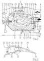
- the cooling air system 1 is shown here using the example of a fan engine, that is to say a two-circuit turbo air jet engine, shown. Of this is only the top half and only the high pressure and combustion chamber area are shown here.
- the compressor 2 is on the left in the figure, the turbine 4 on the right and the combustion chamber 3 in the middle. It is an aircraft engine with a continuous axial design, so that the main and bypass flow i.w. run horizontally from left to right. you recognizes the longitudinal center axis X of the engine, above it the components of the core engine and at the very top the bypass duct 21.
- the compressor 2 is driven by the turbine 4 a shaft 5 driven.
- the compressor 2 is specifically a high-pressure compressor, the turbine 4 a High pressure turbine and the shaft 5 thus a high pressure shaft.
- the components of the Low pressure range, e.g. the low pressure shaft, here are the better overview because of not reproduced.
- a guide vane ring can be seen from the compressor 2, a blade ring with a disc and as a transition element to the combustion chamber 3 the combustion chamber diffuser 7.
- the combustion chamber 3 includes the inner high-temperature zone 8, symbolized by flames where the hot oxidation of the fuel with atmospheric oxygen takes place, as well as the outer combustion chamber jacket 9, which is only of highly compressed Air is flowing through.
- the turbine 4 (high-pressure turbine) is shown in one stage, i.e.
- the cooling air system 1 has the task in each case, the thermally critical guide and Cooling blades 13, 14 optimally. For this purpose, two cooling air flows with very different temperatures but with comparable pressure.
- To at least one low-loss heat exchanger 6 is required, which is arranged here in the cool bypass duct 21
- the total amount of cooling air required is in the present case downstream of the combustion chamber diffuser 7 in the region of the Combustion chamber casing 9 removed. Specifically, there are three separate tapping points 10.1, 1.12, of which the first (10) leads directly to the heat exchanger 6.
- the second (11) leads to a control and admixing valve 22, the third (12) leads from the downstream Combustion chamber end to the blades 14 of the turbine 4.
- Another, not tapping point is located at the radially outer end of each guide vane 13, at the transition to the combustion chamber jacket 9.
- Hotter cooling air is radially radially from the outside through the combustion chamber jacket 9 (top) in the middle profile area of the guide vanes 13, also over the removal point 12 radially from the inside (below) in the middle profile area of the blades 14 of the turbine 4.
- a partial flow of the cooling air is from the tapping point 10 into the heat exchanger 6 Lowering the cooling air temperature.
- the heat exchanger 6 is usually a Air / air heat exchangers, with the heat-absorbing air flow being the fan exhaust air (Bypass air) is. See the left area 23. In the right area is 24 Another possibility of heat transfer is shown, namely from the cooling air on the fuel 25 of the engine. In practical terms, the two Areas 23, 24 are spatially separated, i.e. form separate assemblies / modules.
- To Exit from the heat exchanger 6 is the now significantly cooler cooling air a control and admixing valve 22 guided, which also one of the tapping point 11th Coming supply line for hotter cooling air.
- the temperature of the uncooled cooling air can be varied by varying the ratio adjust the cooling air emerging from the control and admixing valve.
- the volume flow of this cooling air can also be adjusted via the degree of valve opening in extreme cases from "zero" to a maximum value.
- the temperature of this Cooling air is therefore between the value at the compressor outlet and the value at the heat exchanger outlet variable.
- the further flow path of this cooled cooling air leads here by striving the combustion chamber diffuser 7 in the region of the shaft 5 and lengthways this in the turbine area. Because the heat exchanger 6 and the control and admixing valve 22 lead to certain pressure losses in the cooling air flow, it may be necessary to raise its pressure level again.
- the figure shows two examples.
- At 19 is an additional cooling air compressor called, which as an axial compressor directly on the Wave 5 is sitting.
- a cooling air compressor is shown as position 20, which acts as a radial compressor on one side of the turbine disc 15 on a rotating cover plate 18 sits.
- the drive power would also be taken from an engine shaft.
- one of the cooling air compressors mentioned leads the flow path of the cooled cooling air ultimately to and in the guide and rotor blades 13, 14, each in a flow chamber near the leading edge and into one near the trailing edge of each blade.
- the flow guidance in the blades can be explained even better with reference to FIG. 2.
- the blade 26 has a structure typical of guide blades, the principle is also transferable to blades. There are three within the hollow blade 26 Flow chambers 27,28,29 arranged, with an additional space 30th is volumetrically / fluidically attributable to the middle flow chamber 28.
- the front and rear flow chambers 27, 29 are cooled with the same one Cooling air coming from the heat exchanger or from the control and admixing valve.
- the middle flow chamber 28, on the other hand, becomes significantly hotter, uncooled Cooling air supplied.
- the cooling air from the front flow chamber 27 let out.
- the middle flow chamber 28 leaves the hotter cooling air via cooling air bores 32 in the sense of impingement cooling initially into an intermediate space 30 emerge, which extends further forward in relation to the profile than the flow chamber 28 itself, with some heat exchange to the flow chamber 27 is to be expected through the thin inner partition.
- the eventual exit of the Cooling air from the blade profile takes place via the cooling air holes 33.
- the rear one Flow chamber 29 is largely formed by cast contours and has here as A cooling air gap 34 emerges at the trailing edge of the blade.
- FIG. 3 finally qualitatively compares the temperature profile over the profile length a prior art blade, i.e. with cooling by an air stream, with the temperature profile for a blade according to the invention.
- T stands for temperature
- L stands for a length coordinate in the longitudinal direction of the profile, for example on the Profile centerline (chord) or on the profile surface
- Vk stands for leading edge and Hk for rear edge.
- ⁇ T is the maximum temperature difference in the respective profile section and thus a measure of thermally induced component voltages. It can be spotted, that the minimum temperature in the middle profile area in both versions same or comparable level.
- the maximum temperature at the conventionally cooled bucket does not exceed a permissible limit value on the material side, it is more reasonable to curve the blade of the invention so far to raise that their maximum value also corresponds approximately to the material limit value.
Description
Claims (7)
- Kühlluftsystem zur Reduktion der thermischen Bauteilbelastung im Turbinen-Hochdruckbereich von Gasturbinen, die wenigstens einen Verdichter, eine Brennkammer und eine Turbine umfassen, mit kühlluftdurchströmten Schaufel, welche jeweils mehrere, getrennte Strömungskammern im Schaufelblattinneren für unterschiedliche Luftströme aufweisen, und mit einer die Hochtemperaturzone der Brennkammer umgehenden Kühlluftführung vom Hochdruckbereich bzw. Austrittsbereich des Verdichters bis in die Beschaufelung des Hochdruckbereichs der Turbine, wobei
jede der thermisch hochbelasteten Schaufeln (13,14,26) eine Strömungskammer (27) im Bereich ihrer Vorderkante, mindestens eine Strömungskammer (28) im mittleren Bereich ihres Profils sowie eine Strömungskammer (29) im Bereich ihrer Hinterkante aufweist, dadurch gekennzeichnet, dass die Kühlluftführung mindestens einen Wärmetauscher (6) für die Temperaturabsenkung eines Teilstroms der vom Verdichter (2) kommenden Kühlluft sowie wenigstens eine Strömungsverbindung vom Austritt des Wärmetauschers (6) zu der vordersten (27) und zu der hintersten Strömungskammer (29) jeder Schaufel (13,14,26) umfasst, wobei die Kühlluftführung zu der mindestens einen, mittleren Strömungskammer (28) direkt verläuft, d.h. den Wärmetauscher (6) umgeht. - Kühfiuftsystem nach Anspruch 1 für ein Flugtriebwerk in Zweikreisbauart, d.h. ein Fantriebwerk, dadurch gekennzeichnet, dass der Wärmetauscher (6) stromabwärts des Fans im Bypasskanal (21) angeordnet ist.
- Kühlluftsystem nach Anspruch 1 oder 2, dadurch gekennzeichnet, dass für die aus dem Wärmetauscher (6) kommende Kühlluft ein zusätzlicher Kühlluftverdichter (19,20) vorhanden ist, der direkt oder indirekt von einer den Verdichter (2) mit der Turbine (4) koppelnden Welle (5) angetrieben wird.
- Kühlluftsystem nach einem oder mehreren der Ansprüche 1 bis 3, dadurch gekennzeichnet, dass für die aus dem Wärmetauscher (6) austretende Kühlluft eine Einrichtung zur Regelung der Luftmenge sowie ggf. der Lufttemperatur, letzteres durch Zumischung von heißerer, nicht durch den Wärmetauscher geführter Kühlluft, vorhanden ist, vorzugsweise in Form eines Regel- und Zumischventils (22).
- Kühlluftsystem nach einem oder mehreren der Ansprüche 1 bis 4, dadurch gekennzeichnet, dass Stellen (10,11,12) zur Kühlluftentnahme stromabwärts des Verdichters (2) im Bereich des Brennkammermantels (9) vorgesehen sind.
- Kühlluftsystem nach einem oder mehreren der Ansprüche 1 bis 5, dadurch gekennzeichnet, dass die Kühlluftführung für einen Teilstrom der vom Wärmetauscher (6) bzw. vom Regel- und Zumischventil (22) kommenden Kühlluft einen Strömungspfad durch die zentrale Öffnung (16) wenigstens einer Turbinenscheibe (15) umfasst.
- Kühlluftsystem nach einem oder mehreren der Ansprüche 1 bis 6, dadurch gekennzeichnet, dass der Wärmetauscher (6) einen Bereich (23) mit einem Wärmeübergang Kühlluft/Luft sowie einen Bereich (24) mit einem Wärmeübergang Kühlluft/Brennstoff (25) aufweist, wobei die beiden Bereiche (23,24) räumlich zusammengefasst oder voneinander getrennt sein können.
Applications Claiming Priority (3)
| Application Number | Priority Date | Filing Date | Title |
|---|---|---|---|
| DE10009655A DE10009655C1 (de) | 2000-02-29 | 2000-02-29 | Kühlluftsystem |
| DE10009655 | 2000-02-29 | ||
| PCT/DE2001/000725 WO2001065095A1 (de) | 2000-02-29 | 2001-02-24 | Kühlluftsystem |
Publications (2)
| Publication Number | Publication Date |
|---|---|
| EP1173664A1 EP1173664A1 (de) | 2002-01-23 |
| EP1173664B1 true EP1173664B1 (de) | 2004-12-08 |
Family
ID=7632909
Family Applications (1)
| Application Number | Title | Priority Date | Filing Date |
|---|---|---|---|
| EP01915036A Expired - Lifetime EP1173664B1 (de) | 2000-02-29 | 2001-02-24 | Kühlluftsystem |
Country Status (6)
| Country | Link |
|---|---|
| US (1) | US6612114B1 (de) |
| EP (1) | EP1173664B1 (de) |
| JP (1) | JP4554867B2 (de) |
| AT (1) | ATE284483T1 (de) |
| DE (2) | DE10009655C1 (de) |
| WO (1) | WO2001065095A1 (de) |
Families Citing this family (93)
| Publication number | Priority date | Publication date | Assignee | Title |
|---|---|---|---|---|
| US6213714B1 (en) * | 1999-06-29 | 2001-04-10 | Allison Advanced Development Company | Cooled airfoil |
| EP1418319A1 (de) * | 2002-11-11 | 2004-05-12 | Siemens Aktiengesellschaft | Gasturbine |
| US6843059B2 (en) * | 2002-11-19 | 2005-01-18 | General Electric Company | Combustor inlet diffuser with boundary layer blowing |
| US7096673B2 (en) * | 2003-10-08 | 2006-08-29 | Siemens Westinghouse Power Corporation | Blade tip clearance control |
| DE102004029696A1 (de) * | 2004-06-15 | 2006-01-05 | Rolls-Royce Deutschland Ltd & Co Kg | Plattformkühlanordnung für den Leitschaufelkranz einer Gasturbine |
| FR2892454B1 (fr) * | 2005-10-21 | 2008-01-25 | Snecma Sa | Dispositif de ventilation de disques de turbine dans un moteur a turbine a gaz |
| US8668437B1 (en) * | 2006-09-22 | 2014-03-11 | Siemens Energy, Inc. | Turbine engine cooling fluid feed system |
| US7823389B2 (en) * | 2006-11-15 | 2010-11-02 | General Electric Company | Compound clearance control engine |
| JP4304541B2 (ja) | 2007-06-27 | 2009-07-29 | トヨタ自動車株式会社 | 抽気型ガスタービン |
| US20090056342A1 (en) * | 2007-09-04 | 2009-03-05 | General Electric Company | Methods and Systems for Gas Turbine Part-Load Operating Conditions |
| DE102008005163B4 (de) * | 2008-01-19 | 2009-12-03 | Deutsches Zentrum für Luft- und Raumfahrt e.V. | Flugtriebwerk |
| US8079802B2 (en) * | 2008-06-30 | 2011-12-20 | Mitsubishi Heavy Industries, Ltd. | Gas turbine |
| US8517663B2 (en) * | 2008-09-30 | 2013-08-27 | General Electric Company | Method and apparatus for gas turbine engine temperature management |
| GB0818047D0 (en) * | 2008-10-03 | 2008-11-05 | Rolls Royce Plc | Turbine cooling system |
| ES2370308B1 (es) * | 2008-12-31 | 2012-10-22 | Futur Investment Partners, S.A. | Motor aeronáutico. |
| US8307662B2 (en) * | 2009-10-15 | 2012-11-13 | General Electric Company | Gas turbine engine temperature modulated cooling flow |
| US8590603B2 (en) * | 2009-12-08 | 2013-11-26 | Hamilton Sundstrand Corporation | Heat exchanger insulation gap |
| US8256229B2 (en) | 2010-04-09 | 2012-09-04 | United Technologies Corporation | Rear hub cooling for high pressure compressor |
| FR2961857B1 (fr) * | 2010-06-28 | 2012-07-27 | Snecma | Tube d'alimentation en air de refroidissement d'une turbine d'un turbomoteur, et turbomoteur equipe d'un tel tube |
| EP2587021A1 (de) | 2011-10-24 | 2013-05-01 | Siemens Aktiengesellschaft | Gasturbine und Verfahren zum Leiten von Druckflüssigkeit in eine Gasturbine |
| RU2490490C1 (ru) * | 2011-12-14 | 2013-08-20 | Открытое акционерное общество "Научно-производственное объединение "Сатурн" (ОАО "НПО "Сатурн") | Двухконтурный газотурбинный двигатель |
| GB201200139D0 (en) * | 2012-01-06 | 2012-02-15 | Rolls Royce Plc | Coolant supply system |
| US9091173B2 (en) | 2012-05-31 | 2015-07-28 | United Technologies Corporation | Turbine coolant supply system |
| RU2514818C1 (ru) * | 2013-02-27 | 2014-05-10 | Открытое акционерное общество "Уфимское моторостроительное производственное объединение" ОАО "УМПО" | Охлаждаемая турбина |
| RU2518768C1 (ru) * | 2013-04-04 | 2014-06-10 | Открытое акционерное общество "Уфимское моторостроительное производственное объединение" ОАО "УМПО" | Охлаждаемая турбина |
| RU2518729C1 (ru) * | 2013-04-04 | 2014-06-10 | Открытое акционерное общество "Уфимское моторостроительное производственное объединение" ОАО "УМПО" | Охлаждаемая турбина |
| RU2553919C2 (ru) * | 2013-05-27 | 2015-06-20 | Николай Борисович Болотин | Газотурбинный двигатель |
| US9512780B2 (en) * | 2013-07-31 | 2016-12-06 | General Electric Company | Heat transfer assembly and methods of assembling the same |
| US10612469B2 (en) * | 2013-08-05 | 2020-04-07 | United Technologies Corporation | Diffuser case mixing chamber for a turbine engine |
| US10677161B2 (en) | 2013-08-28 | 2020-06-09 | Raytheon Technologies Corporation | Gas turbine engine diffuser cooling and mixing arrangement |
| RU2532737C1 (ru) * | 2013-12-09 | 2014-11-10 | Николай Борисович Болотин | Газотурбинный двигатель |
| RU2583492C2 (ru) * | 2014-03-28 | 2016-05-10 | Открытое Акционерное общество "Научно-производственное предприятие "Мотор" | Устройство подвода охладителя к охлаждаемым рабочим лопаткам высокотемпературной газовой турбины |
| RU2562361C1 (ru) * | 2014-04-14 | 2015-09-10 | Федеральное государственное унитарное предприятие "Центральный институт авиационного моторостроения имени П.И. Баранова" | Способ охлаждения рабочей лопатки турбины газотурбинного двигателя |
| US20170328231A1 (en) * | 2014-05-09 | 2017-11-16 | United Technologies Corporation | Turbine clearance control system and method for improved variable cycle gas turbine engine fuel burn |
| US9341119B2 (en) * | 2014-07-03 | 2016-05-17 | Hamilton Sundstrand Corporation | Cooling air system for aircraft turbine engine |
| US10415478B2 (en) | 2015-01-20 | 2019-09-17 | United Technologies Corporation | Air mixing systems having mixing chambers for gas turbine engines |
| US10100738B2 (en) * | 2015-01-20 | 2018-10-16 | United Technologies Corporation | Overcooled air cooling system with annular mixing passage |
| US10371055B2 (en) | 2015-02-12 | 2019-08-06 | United Technologies Corporation | Intercooled cooling air using cooling compressor as starter |
| US11808210B2 (en) | 2015-02-12 | 2023-11-07 | Rtx Corporation | Intercooled cooling air with heat exchanger packaging |
| US10731560B2 (en) | 2015-02-12 | 2020-08-04 | Raytheon Technologies Corporation | Intercooled cooling air |
| US10480419B2 (en) | 2015-04-24 | 2019-11-19 | United Technologies Corporation | Intercooled cooling air with plural heat exchangers |
| US10221862B2 (en) | 2015-04-24 | 2019-03-05 | United Technologies Corporation | Intercooled cooling air tapped from plural locations |
| US10830148B2 (en) * | 2015-04-24 | 2020-11-10 | Raytheon Technologies Corporation | Intercooled cooling air with dual pass heat exchanger |
| US9850819B2 (en) * | 2015-04-24 | 2017-12-26 | United Technologies Corporation | Intercooled cooling air with dual pass heat exchanger |
| US10100739B2 (en) | 2015-05-18 | 2018-10-16 | United Technologies Corporation | Cooled cooling air system for a gas turbine engine |
| US9850818B2 (en) | 2015-06-29 | 2017-12-26 | General Electric Company | Power generation system exhaust cooling |
| US9856768B2 (en) | 2015-06-29 | 2018-01-02 | General Electric Company | Power generation system exhaust cooling |
| US10077694B2 (en) | 2015-06-29 | 2018-09-18 | General Electric Company | Power generation system exhaust cooling |
| US9840953B2 (en) | 2015-06-29 | 2017-12-12 | General Electric Company | Power generation system exhaust cooling |
| US10087801B2 (en) | 2015-06-29 | 2018-10-02 | General Electric Company | Power generation system exhaust cooling |
| US10030558B2 (en) | 2015-06-29 | 2018-07-24 | General Electric Company | Power generation system exhaust cooling |
| US10215070B2 (en) * | 2015-06-29 | 2019-02-26 | General Electric Company | Power generation system exhaust cooling |
| US9752502B2 (en) | 2015-06-29 | 2017-09-05 | General Electric Company | Power generation system exhaust cooling |
| US9752503B2 (en) | 2015-06-29 | 2017-09-05 | General Electric Company | Power generation system exhaust cooling |
| US9850794B2 (en) | 2015-06-29 | 2017-12-26 | General Electric Company | Power generation system exhaust cooling |
| US10060316B2 (en) | 2015-06-29 | 2018-08-28 | General Electric Company | Power generation system exhaust cooling |
| US9938874B2 (en) | 2015-06-29 | 2018-04-10 | General Electric Company | Power generation system exhaust cooling |
| US10794288B2 (en) | 2015-07-07 | 2020-10-06 | Raytheon Technologies Corporation | Cooled cooling air system for a turbofan engine |
| US10330010B2 (en) | 2015-12-14 | 2019-06-25 | United Technologies Corporation | Compressor core inner diameter cooling |
| US10443508B2 (en) | 2015-12-14 | 2019-10-15 | United Technologies Corporation | Intercooled cooling air with auxiliary compressor control |
| US20170184027A1 (en) * | 2015-12-29 | 2017-06-29 | General Electric Company | Method and system for compressor and turbine cooling |
| RU2634981C2 (ru) * | 2016-04-20 | 2017-11-08 | Акционерное общество "Климов" | Газогенератор газотурбинного двигателя |
| JP6647952B2 (ja) * | 2016-04-25 | 2020-02-14 | 三菱重工業株式会社 | ガスタービン |
| US10316759B2 (en) | 2016-05-31 | 2019-06-11 | General Electric Company | Power generation system exhaust cooling |
| RU2627748C1 (ru) * | 2016-06-01 | 2017-08-11 | Публичное акционерное общество "Уфимское моторостроительное производственное объединение" ПАО "УМПО" | Охлаждаемая турбина двухконтурного газотурбинного двигателя |
| US10669940B2 (en) | 2016-09-19 | 2020-06-02 | Raytheon Technologies Corporation | Gas turbine engine with intercooled cooling air and turbine drive |
| US10550768B2 (en) | 2016-11-08 | 2020-02-04 | United Technologies Corporation | Intercooled cooled cooling integrated air cycle machine |
| US10794290B2 (en) | 2016-11-08 | 2020-10-06 | Raytheon Technologies Corporation | Intercooled cooled cooling integrated air cycle machine |
| US10961911B2 (en) | 2017-01-17 | 2021-03-30 | Raytheon Technologies Corporation | Injection cooled cooling air system for a gas turbine engine |
| US10995673B2 (en) | 2017-01-19 | 2021-05-04 | Raytheon Technologies Corporation | Gas turbine engine with intercooled cooling air and dual towershaft accessory gearbox |
| RU2639443C1 (ru) * | 2017-01-24 | 2017-12-21 | Публичное акционерное общество "ОДК - Уфимское моторостроительное производственное объединение" (ПАО "ОДК-УМПО") | Охлаждаемая турбина двухконтурного газотурбинного двигателя |
| US11215120B2 (en) * | 2017-02-06 | 2022-01-04 | Raytheon Technologies Corporation | External mixing chamber for a gas turbine engine with cooled turbine cooling air |
| WO2018164598A1 (en) | 2017-03-09 | 2018-09-13 | Siemens Aktiengesellschaft | Supply system of gas turbine component cooling |
| US10577964B2 (en) | 2017-03-31 | 2020-03-03 | United Technologies Corporation | Cooled cooling air for blade air seal through outer chamber |
| US20180291760A1 (en) * | 2017-04-11 | 2018-10-11 | United Technologies Corporation | Cooling air chamber for blade outer air seal |
| US10711640B2 (en) | 2017-04-11 | 2020-07-14 | Raytheon Technologies Corporation | Cooled cooling air to blade outer air seal passing through a static vane |
| US11268444B2 (en) * | 2017-05-18 | 2022-03-08 | Raytheon Technologies Corporation | Turbine cooling arrangement |
| US10907545B2 (en) * | 2017-06-27 | 2021-02-02 | General Electric Company | Cooling system for a turbine engine |
| US10738703B2 (en) | 2018-03-22 | 2020-08-11 | Raytheon Technologies Corporation | Intercooled cooling air with combined features |
| US10808572B2 (en) * | 2018-04-02 | 2020-10-20 | General Electric Company | Cooling structure for a turbomachinery component |
| EP3550106A1 (de) * | 2018-04-06 | 2019-10-09 | Frederick M. Schwarz | Kühlluft für gasturbinenmotor mit thermisch isolierter kühlluftführung |
| US10830145B2 (en) | 2018-04-19 | 2020-11-10 | Raytheon Technologies Corporation | Intercooled cooling air fleet management system |
| US10808619B2 (en) | 2018-04-19 | 2020-10-20 | Raytheon Technologies Corporation | Intercooled cooling air with advanced cooling system |
| RU2683053C1 (ru) * | 2018-05-24 | 2019-03-26 | Публичное акционерное общество "ОДК - Уфимское моторостроительное производственное объединение" (ПАО "ОДК-УМПО") | Сопловый аппарат турбины высокого давления (ТВД) газотурбинного двигателя (варианты), сопловый венец соплового аппарата ТВД и лопатка соплового аппарата ТВД |
| US10718233B2 (en) | 2018-06-19 | 2020-07-21 | Raytheon Technologies Corporation | Intercooled cooling air with low temperature bearing compartment air |
| RU2691868C1 (ru) * | 2018-07-05 | 2019-06-18 | Публичное акционерное общество "ОДК-Уфимское моторостроительное производственное объединение" (ПАО "ОДК-УМПО") | Ротор турбины высокого давления газотурбинного двигателя (варианты) |
| RU2684298C1 (ru) * | 2018-07-05 | 2019-04-05 | Публичное акционерное общество "ОДК-Уфимское моторостроительное производственное объединение" (ПАО "ОДК-УМПО") | Способ охлаждения ротора турбины высокого давления (ТВД) газотурбинного двигателя (ГТД), ротор ТВД и лопатка ротора ТВД, охлаждаемые этим способом, узел аппарата закрутки воздуха ротора ТВД |
| US11530650B2 (en) | 2018-07-13 | 2022-12-20 | Raytheon Technologies Corporation | Gas turbine engine with active variable turbine cooling |
| US11255268B2 (en) | 2018-07-31 | 2022-02-22 | Raytheon Technologies Corporation | Intercooled cooling air with selective pressure dump |
| US11591915B2 (en) * | 2019-09-30 | 2023-02-28 | Raytheon Technologies Corporation | Multi-flow cooling circuit for gas turbine engine flowpath component |
| IT202100000296A1 (it) | 2021-01-08 | 2022-07-08 | Gen Electric | Motore a turbine con paletta avente un insieme di fossette |
| US11788470B2 (en) * | 2021-03-01 | 2023-10-17 | General Electric Company | Gas turbine engine thermal management |
| DE102021004405A1 (de) | 2021-08-30 | 2023-03-02 | Erich Würzinger | Verfahren zur effektiven Mischungs-Methodologie, Gemischbildung, fortschrittlicher Kraftstoffaufbereitung in einer emissionsarmen Brennkammer und zur Erzeugung von variabler Geometrie in Brennkammer und in der Hochdruckturbinenkapazität durch die Anwendung von komprimierter Verdichterzapfluft zur Anwendung in Fluggasturbinen und stationären Gasturbinen |
Family Cites Families (18)
| Publication number | Priority date | Publication date | Assignee | Title |
|---|---|---|---|---|
| US4254618A (en) * | 1977-08-18 | 1981-03-10 | General Electric Company | Cooling air cooler for a gas turbofan engine |
| JPS58129529A (ja) | 1982-01-28 | 1983-08-02 | Canon Inc | 文字処理装置 |
| JPS6022003A (ja) * | 1983-07-18 | 1985-02-04 | Hitachi Ltd | ガスタ−ビン翼冷却方法 |
| US5144794A (en) * | 1989-08-25 | 1992-09-08 | Hitachi, Ltd. | Gas turbine engine with cooling of turbine blades |
| FR2656657A1 (fr) * | 1989-12-28 | 1991-07-05 | Snecma | Turbomachine refroidie par air et procede de refroidissement de cette turbomachine. |
| US5813835A (en) * | 1991-08-19 | 1998-09-29 | The United States Of America As Represented By The Secretary Of The Air Force | Air-cooled turbine blade |
| US5320483A (en) * | 1992-12-30 | 1994-06-14 | General Electric Company | Steam and air cooling for stator stage of a turbine |
| FR2708669B1 (fr) * | 1993-08-05 | 1995-09-08 | Snecma | Système de ventilation des disques et du stator de turbine d'un turboréacteur. |
| JPH07279612A (ja) * | 1994-04-14 | 1995-10-27 | Mitsubishi Heavy Ind Ltd | 重質油焚き用ガスタービン冷却翼 |
| US5579631A (en) * | 1994-04-28 | 1996-12-03 | Westinghouse Electric Corporation | Steam cooling of gas turbine with backup air cooling |
| US5498126A (en) * | 1994-04-28 | 1996-03-12 | United Technologies Corporation | Airfoil with dual source cooling |
| US5591002A (en) * | 1994-08-23 | 1997-01-07 | General Electric Co. | Closed or open air cooling circuits for nozzle segments with wheelspace purge |
| GB2299378A (en) * | 1995-03-25 | 1996-10-02 | Rolls Royce Plc | Cooling compressor guide vanes |
| US5591007A (en) * | 1995-05-31 | 1997-01-07 | General Electric Company | Multi-tier turbine airfoil |
| US5782076A (en) * | 1996-05-17 | 1998-07-21 | Westinghouse Electric Corporation | Closed loop air cooling system for combustion turbines |
| DE19629191C2 (de) * | 1996-07-19 | 1998-05-14 | Siemens Ag | Verfahren zur Kühlung einer Gasturbine |
| DE19733148C1 (de) * | 1997-07-31 | 1998-11-12 | Siemens Ag | Kühlluftverteilung in einer Turbinenstufe einer Gasturbine |
| JPH1193694A (ja) * | 1997-09-18 | 1999-04-06 | Toshiba Corp | ガスタービンプラント |
-
2000
- 2000-02-29 DE DE10009655A patent/DE10009655C1/de not_active Expired - Fee Related
-
2001
- 2001-02-24 DE DE2001504743 patent/DE50104743D1/de not_active Expired - Lifetime
- 2001-02-24 AT AT01915036T patent/ATE284483T1/de not_active IP Right Cessation
- 2001-02-24 JP JP2001563767A patent/JP4554867B2/ja not_active Expired - Fee Related
- 2001-02-24 WO PCT/DE2001/000725 patent/WO2001065095A1/de active IP Right Grant
- 2001-02-24 EP EP01915036A patent/EP1173664B1/de not_active Expired - Lifetime
-
2002
- 2002-03-18 US US10/018,272 patent/US6612114B1/en not_active Expired - Lifetime
Also Published As
| Publication number | Publication date |
|---|---|
| JP4554867B2 (ja) | 2010-09-29 |
| EP1173664A1 (de) | 2002-01-23 |
| JP2003525384A (ja) | 2003-08-26 |
| DE50104743D1 (de) | 2005-01-13 |
| US6612114B1 (en) | 2003-09-02 |
| DE10009655C1 (de) | 2001-05-23 |
| ATE284483T1 (de) | 2004-12-15 |
| WO2001065095A1 (de) | 2001-09-07 |
Similar Documents
| Publication | Publication Date | Title |
|---|---|---|
| EP1173664B1 (de) | Kühlluftsystem | |
| DE60032042T2 (de) | Kühlsystem für Gasturbinen | |
| EP1789654B1 (de) | Strömungsmaschinenschaufel mit fluidisch gekühltem deckband | |
| EP1320661B1 (de) | Gasturbinenschaufel | |
| DE102007007177B4 (de) | Verfahren und Vorrichtung zum Kühlen von Gasturbinen- Rotorschaufeln | |
| DE60018817T2 (de) | Gekühlte Gasturbinenschaufel | |
| DE4411616C2 (de) | Verfahren zum Betreiben einer Strömungsmaschine | |
| DE3424229A1 (de) | Kuehlluftstroemungs-modulationseinrichtung fuer eine gasturbine | |
| DE112016005433B4 (de) | Gasturbine und bauteiltemperatur-einstellverfahren dafür | |
| DE69923914T2 (de) | Strömungsmaschinenschaufel mit aparter Kühlung der Anströmkante | |
| DE3040594A1 (de) | Spaltsteuervorrichtung fuer eine turbomaschine | |
| EP1614859A1 (de) | Filmgekühlte Turbinenschaufel | |
| EP1904717B1 (de) | HEIßGASFÜHRENDES GEHÄUSEELEMENT, WELLENSCHUTZMANTEL UND GASTURBINENANLAGE | |
| EP2084368B1 (de) | Turbinenschaufel | |
| WO2014033220A1 (de) | Kühlverfahren zum betreiben einer gasturbine | |
| WO2005019621A1 (de) | Diffusor zwischen verdichter und brennkammer einer gasturbine angeordnet | |
| EP2676023A1 (de) | Verfahren zum kühlen der turbinenstufe und gasturbine mit einer gekühlten turbinenstufe | |
| EP1249578B1 (de) | Kühlung einer Gasturbine | |
| DE1601563B2 (de) | Luftgekühlte Laufschaufel | |
| WO1998013584A1 (de) | Kompensation des druckverlustes einer kühlluftführung in einer gasturbinenanlage | |
| EP1167721B1 (de) | Verfahren zum Kühlen einer Gasturbinenanlage sowie Gasturbinenanlage zur Durchführung des Verfahrens | |
| WO2000060219A1 (de) | Strömungsmaschine mit einer kühlbaren anordnung von wandelementen und verfahren zur kühlung einer anordnung von wandelementen | |
| EP1164273B1 (de) | Turboluftstrahltriebwerk mit Wärmetauscher | |
| EP1247943A1 (de) | Formstück zur Bildung eines kühlbaren Turbinen-Mantelrings | |
| EP2324208A1 (de) | Turbinenleitschaufelträger für eine gasturbine und verfahren zum betrieb einer gasturbine |
Legal Events
| Date | Code | Title | Description |
|---|---|---|---|
| PUAI | Public reference made under article 153(3) epc to a published international application that has entered the european phase |
Free format text: ORIGINAL CODE: 0009012 |
|
| 17P | Request for examination filed |
Effective date: 20011024 |
|
| AK | Designated contracting states |
Kind code of ref document: A1 Designated state(s): AT BE CH CY DE DK ES FI FR GB GR IE IT LI LU MC NL PT SE TR |
|
| GRAP | Despatch of communication of intention to grant a patent |
Free format text: ORIGINAL CODE: EPIDOSNIGR1 |
|
| GRAA | (expected) grant |
Free format text: ORIGINAL CODE: 0009210 |
|
| GRAS | Grant fee paid |
Free format text: ORIGINAL CODE: EPIDOSNIGR3 |
|
| AK | Designated contracting states |
Kind code of ref document: B1 Designated state(s): AT BE CH CY DE DK ES FI FR GB GR IE IT LI LU MC NL PT SE TR |
|
| PG25 | Lapsed in a contracting state [announced via postgrant information from national office to epo] |
Ref country code: IT Free format text: LAPSE BECAUSE OF FAILURE TO SUBMIT A TRANSLATION OF THE DESCRIPTION OR TO PAY THE FEE WITHIN THE PRESCRIBED TIME-LIMIT;WARNING: LAPSES OF ITALIAN PATENTS WITH EFFECTIVE DATE BEFORE 2007 MAY HAVE OCCURRED AT ANY TIME BEFORE 2007. THE CORRECT EFFECTIVE DATE MAY BE DIFFERENT FROM THE ONE RECORDED. Effective date: 20041208 Ref country code: FI Free format text: LAPSE BECAUSE OF FAILURE TO SUBMIT A TRANSLATION OF THE DESCRIPTION OR TO PAY THE FEE WITHIN THE PRESCRIBED TIME-LIMIT Effective date: 20041208 Ref country code: NL Free format text: LAPSE BECAUSE OF FAILURE TO SUBMIT A TRANSLATION OF THE DESCRIPTION OR TO PAY THE FEE WITHIN THE PRESCRIBED TIME-LIMIT Effective date: 20041208 Ref country code: IE Free format text: LAPSE BECAUSE OF FAILURE TO SUBMIT A TRANSLATION OF THE DESCRIPTION OR TO PAY THE FEE WITHIN THE PRESCRIBED TIME-LIMIT Effective date: 20041208 Ref country code: TR Free format text: LAPSE BECAUSE OF FAILURE TO SUBMIT A TRANSLATION OF THE DESCRIPTION OR TO PAY THE FEE WITHIN THE PRESCRIBED TIME-LIMIT Effective date: 20041208 |
|
| REG | Reference to a national code |
Ref country code: GB Ref legal event code: FG4D Free format text: NOT ENGLISH |
|
| REG | Reference to a national code |
Ref country code: CH Ref legal event code: EP Ref country code: CH Ref legal event code: NV Representative=s name: ISLER & PEDRAZZINI AG |
|
| REG | Reference to a national code |
Ref country code: IE Ref legal event code: FG4D Free format text: GERMAN |
|
| REF | Corresponds to: |
Ref document number: 50104743 Country of ref document: DE Date of ref document: 20050113 Kind code of ref document: P |
|
| PG25 | Lapsed in a contracting state [announced via postgrant information from national office to epo] |
Ref country code: LU Free format text: LAPSE BECAUSE OF NON-PAYMENT OF DUE FEES Effective date: 20050224 Ref country code: CY Free format text: LAPSE BECAUSE OF FAILURE TO SUBMIT A TRANSLATION OF THE DESCRIPTION OR TO PAY THE FEE WITHIN THE PRESCRIBED TIME-LIMIT Effective date: 20050224 Ref country code: AT Free format text: LAPSE BECAUSE OF NON-PAYMENT OF DUE FEES Effective date: 20050224 |
|
| PG25 | Lapsed in a contracting state [announced via postgrant information from national office to epo] |
Ref country code: MC Free format text: LAPSE BECAUSE OF NON-PAYMENT OF DUE FEES Effective date: 20050228 Ref country code: BE Free format text: LAPSE BECAUSE OF NON-PAYMENT OF DUE FEES Effective date: 20050228 |
|
| PG25 | Lapsed in a contracting state [announced via postgrant information from national office to epo] |
Ref country code: DK Free format text: LAPSE BECAUSE OF FAILURE TO SUBMIT A TRANSLATION OF THE DESCRIPTION OR TO PAY THE FEE WITHIN THE PRESCRIBED TIME-LIMIT Effective date: 20050308 Ref country code: GR Free format text: LAPSE BECAUSE OF FAILURE TO SUBMIT A TRANSLATION OF THE DESCRIPTION OR TO PAY THE FEE WITHIN THE PRESCRIBED TIME-LIMIT Effective date: 20050308 |
|
| REG | Reference to a national code |
Ref country code: SE Ref legal event code: TRGR |
|
| GBT | Gb: translation of ep patent filed (gb section 77(6)(a)/1977) |
Effective date: 20050225 |
|
| NLV1 | Nl: lapsed or annulled due to failure to fulfill the requirements of art. 29p and 29m of the patents act | ||
| REG | Reference to a national code |
Ref country code: IE Ref legal event code: FD4D |
|
| BERE | Be: lapsed |
Owner name: MTU AERO ENGINES G.M.B.H. Effective date: 20050228 |
|
| PLBE | No opposition filed within time limit |
Free format text: ORIGINAL CODE: 0009261 |
|
| STAA | Information on the status of an ep patent application or granted ep patent |
Free format text: STATUS: NO OPPOSITION FILED WITHIN TIME LIMIT |
|
| ET | Fr: translation filed | ||
| 26N | No opposition filed |
Effective date: 20050909 |
|
| REG | Reference to a national code |
Ref country code: CH Ref legal event code: PCAR Free format text: ISLER & PEDRAZZINI AG;POSTFACH 1772;8027 ZUERICH (CH) |
|
| BERE | Be: lapsed |
Owner name: *MTU AERO ENGINES G.M.B.H. Effective date: 20050228 |
|
| PG25 | Lapsed in a contracting state [announced via postgrant information from national office to epo] |
Ref country code: PT Free format text: LAPSE BECAUSE OF NON-PAYMENT OF DUE FEES Effective date: 20050508 |
|
| PGFP | Annual fee paid to national office [announced via postgrant information from national office to epo] |
Ref country code: ES Payment date: 20070228 Year of fee payment: 7 |
|
| PG25 | Lapsed in a contracting state [announced via postgrant information from national office to epo] |
Ref country code: ES Free format text: LAPSE BECAUSE OF FAILURE TO SUBMIT A TRANSLATION OF THE DESCRIPTION OR TO PAY THE FEE WITHIN THE PRESCRIBED TIME-LIMIT Effective date: 20050319 |
|
| REG | Reference to a national code |
Ref country code: FR Ref legal event code: PLFP Year of fee payment: 16 |
|
| REG | Reference to a national code |
Ref country code: FR Ref legal event code: PLFP Year of fee payment: 17 |
|
| REG | Reference to a national code |
Ref country code: FR Ref legal event code: PLFP Year of fee payment: 18 |
|
| PGFP | Annual fee paid to national office [announced via postgrant information from national office to epo] |
Ref country code: GB Payment date: 20190221 Year of fee payment: 19 Ref country code: DE Payment date: 20190219 Year of fee payment: 19 Ref country code: CH Payment date: 20190221 Year of fee payment: 19 |
|
| PGFP | Annual fee paid to national office [announced via postgrant information from national office to epo] |
Ref country code: SE Payment date: 20190221 Year of fee payment: 19 Ref country code: FR Payment date: 20190221 Year of fee payment: 19 |
|
| REG | Reference to a national code |
Ref country code: DE Ref legal event code: R119 Ref document number: 50104743 Country of ref document: DE |
|
| REG | Reference to a national code |
Ref country code: SE Ref legal event code: EUG |
|
| REG | Reference to a national code |
Ref country code: CH Ref legal event code: PL |
|
| GBPC | Gb: european patent ceased through non-payment of renewal fee |
Effective date: 20200224 |
|
| PG25 | Lapsed in a contracting state [announced via postgrant information from national office to epo] |
Ref country code: SE Free format text: LAPSE BECAUSE OF NON-PAYMENT OF DUE FEES Effective date: 20200225 |
|
| PG25 | Lapsed in a contracting state [announced via postgrant information from national office to epo] |
Ref country code: CH Free format text: LAPSE BECAUSE OF NON-PAYMENT OF DUE FEES Effective date: 20200229 Ref country code: LI Free format text: LAPSE BECAUSE OF NON-PAYMENT OF DUE FEES Effective date: 20200229 |
|
| PG25 | Lapsed in a contracting state [announced via postgrant information from national office to epo] |
Ref country code: DE Free format text: LAPSE BECAUSE OF NON-PAYMENT OF DUE FEES Effective date: 20200901 Ref country code: GB Free format text: LAPSE BECAUSE OF NON-PAYMENT OF DUE FEES Effective date: 20200224 Ref country code: FR Free format text: LAPSE BECAUSE OF NON-PAYMENT OF DUE FEES Effective date: 20200229 |