EP3550106A1 - Kühlluft für gasturbinenmotor mit thermisch isolierter kühlluftführung - Google Patents
Kühlluft für gasturbinenmotor mit thermisch isolierter kühlluftführung Download PDFInfo
- Publication number
- EP3550106A1 EP3550106A1 EP19167088.4A EP19167088A EP3550106A1 EP 3550106 A1 EP3550106 A1 EP 3550106A1 EP 19167088 A EP19167088 A EP 19167088A EP 3550106 A1 EP3550106 A1 EP 3550106A1
- Authority
- EP
- European Patent Office
- Prior art keywords
- gas turbine
- turbine engine
- rotating surface
- downstream
- set forth
- Prior art date
- Legal status (The legal status is an assumption and is not a legal conclusion. Google has not performed a legal analysis and makes no representation as to the accuracy of the status listed.)
- Granted
Links
Images
Classifications
-
- F—MECHANICAL ENGINEERING; LIGHTING; HEATING; WEAPONS; BLASTING
- F01—MACHINES OR ENGINES IN GENERAL; ENGINE PLANTS IN GENERAL; STEAM ENGINES
- F01D—NON-POSITIVE DISPLACEMENT MACHINES OR ENGINES, e.g. STEAM TURBINES
- F01D5/00—Blades; Blade-carrying members; Heating, heat-insulating, cooling or antivibration means on the blades or the members
- F01D5/02—Blade-carrying members, e.g. rotors
- F01D5/08—Heating, heat-insulating or cooling means
- F01D5/081—Cooling fluid being directed on the side of the rotor disc or at the roots of the blades
-
- F—MECHANICAL ENGINEERING; LIGHTING; HEATING; WEAPONS; BLASTING
- F01—MACHINES OR ENGINES IN GENERAL; ENGINE PLANTS IN GENERAL; STEAM ENGINES
- F01D—NON-POSITIVE DISPLACEMENT MACHINES OR ENGINES, e.g. STEAM TURBINES
- F01D25/00—Component parts, details, or accessories, not provided for in, or of interest apart from, other groups
- F01D25/08—Cooling; Heating; Heat-insulation
- F01D25/14—Casings modified therefor
- F01D25/145—Thermally insulated casings
-
- F—MECHANICAL ENGINEERING; LIGHTING; HEATING; WEAPONS; BLASTING
- F02—COMBUSTION ENGINES; HOT-GAS OR COMBUSTION-PRODUCT ENGINE PLANTS
- F02C—GAS-TURBINE PLANTS; AIR INTAKES FOR JET-PROPULSION PLANTS; CONTROLLING FUEL SUPPLY IN AIR-BREATHING JET-PROPULSION PLANTS
- F02C6/00—Plural gas-turbine plants; Combinations of gas-turbine plants with other apparatus; Adaptations of gas-turbine plants for special use
- F02C6/04—Gas-turbine plants providing heated or pressurised working fluid for other apparatus, e.g. without mechanical power output
- F02C6/06—Gas-turbine plants providing heated or pressurised working fluid for other apparatus, e.g. without mechanical power output providing compressed gas
- F02C6/08—Gas-turbine plants providing heated or pressurised working fluid for other apparatus, e.g. without mechanical power output providing compressed gas the gas being bled from the gas-turbine compressor
-
- F—MECHANICAL ENGINEERING; LIGHTING; HEATING; WEAPONS; BLASTING
- F02—COMBUSTION ENGINES; HOT-GAS OR COMBUSTION-PRODUCT ENGINE PLANTS
- F02C—GAS-TURBINE PLANTS; AIR INTAKES FOR JET-PROPULSION PLANTS; CONTROLLING FUEL SUPPLY IN AIR-BREATHING JET-PROPULSION PLANTS
- F02C7/00—Features, components parts, details or accessories, not provided for in, or of interest apart form groups F02C1/00 - F02C6/00; Air intakes for jet-propulsion plants
- F02C7/12—Cooling of plants
- F02C7/16—Cooling of plants characterised by cooling medium
- F02C7/18—Cooling of plants characterised by cooling medium the medium being gaseous, e.g. air
- F02C7/185—Cooling means for reducing the temperature of the cooling air or gas
-
- F—MECHANICAL ENGINEERING; LIGHTING; HEATING; WEAPONS; BLASTING
- F02—COMBUSTION ENGINES; HOT-GAS OR COMBUSTION-PRODUCT ENGINE PLANTS
- F02C—GAS-TURBINE PLANTS; AIR INTAKES FOR JET-PROPULSION PLANTS; CONTROLLING FUEL SUPPLY IN AIR-BREATHING JET-PROPULSION PLANTS
- F02C7/00—Features, components parts, details or accessories, not provided for in, or of interest apart form groups F02C1/00 - F02C6/00; Air intakes for jet-propulsion plants
- F02C7/24—Heat or noise insulation
-
- F—MECHANICAL ENGINEERING; LIGHTING; HEATING; WEAPONS; BLASTING
- F02—COMBUSTION ENGINES; HOT-GAS OR COMBUSTION-PRODUCT ENGINE PLANTS
- F02C—GAS-TURBINE PLANTS; AIR INTAKES FOR JET-PROPULSION PLANTS; CONTROLLING FUEL SUPPLY IN AIR-BREATHING JET-PROPULSION PLANTS
- F02C9/00—Controlling gas-turbine plants; Controlling fuel supply in air- breathing jet-propulsion plants
- F02C9/16—Control of working fluid flow
- F02C9/18—Control of working fluid flow by bleeding, bypassing or acting on variable working fluid interconnections between turbines or compressors or their stages
-
- F—MECHANICAL ENGINEERING; LIGHTING; HEATING; WEAPONS; BLASTING
- F05—INDEXING SCHEMES RELATING TO ENGINES OR PUMPS IN VARIOUS SUBCLASSES OF CLASSES F01-F04
- F05D—INDEXING SCHEME FOR ASPECTS RELATING TO NON-POSITIVE-DISPLACEMENT MACHINES OR ENGINES, GAS-TURBINES OR JET-PROPULSION PLANTS
- F05D2220/00—Application
- F05D2220/30—Application in turbines
- F05D2220/32—Application in turbines in gas turbines
-
- F—MECHANICAL ENGINEERING; LIGHTING; HEATING; WEAPONS; BLASTING
- F05—INDEXING SCHEMES RELATING TO ENGINES OR PUMPS IN VARIOUS SUBCLASSES OF CLASSES F01-F04
- F05D—INDEXING SCHEME FOR ASPECTS RELATING TO NON-POSITIVE-DISPLACEMENT MACHINES OR ENGINES, GAS-TURBINES OR JET-PROPULSION PLANTS
- F05D2230/00—Manufacture
- F05D2230/90—Coating; Surface treatment
-
- F—MECHANICAL ENGINEERING; LIGHTING; HEATING; WEAPONS; BLASTING
- F05—INDEXING SCHEMES RELATING TO ENGINES OR PUMPS IN VARIOUS SUBCLASSES OF CLASSES F01-F04
- F05D—INDEXING SCHEME FOR ASPECTS RELATING TO NON-POSITIVE-DISPLACEMENT MACHINES OR ENGINES, GAS-TURBINES OR JET-PROPULSION PLANTS
- F05D2240/00—Components
- F05D2240/60—Shafts
-
- F—MECHANICAL ENGINEERING; LIGHTING; HEATING; WEAPONS; BLASTING
- F05—INDEXING SCHEMES RELATING TO ENGINES OR PUMPS IN VARIOUS SUBCLASSES OF CLASSES F01-F04
- F05D—INDEXING SCHEME FOR ASPECTS RELATING TO NON-POSITIVE-DISPLACEMENT MACHINES OR ENGINES, GAS-TURBINES OR JET-PROPULSION PLANTS
- F05D2300/00—Materials; Properties thereof
- F05D2300/20—Oxide or non-oxide ceramics
- F05D2300/21—Oxide ceramics
- F05D2300/2118—Zirconium oxides
-
- F—MECHANICAL ENGINEERING; LIGHTING; HEATING; WEAPONS; BLASTING
- F05—INDEXING SCHEMES RELATING TO ENGINES OR PUMPS IN VARIOUS SUBCLASSES OF CLASSES F01-F04
- F05D—INDEXING SCHEME FOR ASPECTS RELATING TO NON-POSITIVE-DISPLACEMENT MACHINES OR ENGINES, GAS-TURBINES OR JET-PROPULSION PLANTS
- F05D2300/00—Materials; Properties thereof
- F05D2300/20—Oxide or non-oxide ceramics
- F05D2300/22—Non-oxide ceramics
-
- F—MECHANICAL ENGINEERING; LIGHTING; HEATING; WEAPONS; BLASTING
- F05—INDEXING SCHEMES RELATING TO ENGINES OR PUMPS IN VARIOUS SUBCLASSES OF CLASSES F01-F04
- F05D—INDEXING SCHEME FOR ASPECTS RELATING TO NON-POSITIVE-DISPLACEMENT MACHINES OR ENGINES, GAS-TURBINES OR JET-PROPULSION PLANTS
- F05D2300/00—Materials; Properties thereof
- F05D2300/60—Properties or characteristics given to material by treatment or manufacturing
- F05D2300/614—Fibres or filaments
-
- Y—GENERAL TAGGING OF NEW TECHNOLOGICAL DEVELOPMENTS; GENERAL TAGGING OF CROSS-SECTIONAL TECHNOLOGIES SPANNING OVER SEVERAL SECTIONS OF THE IPC; TECHNICAL SUBJECTS COVERED BY FORMER USPC CROSS-REFERENCE ART COLLECTIONS [XRACs] AND DIGESTS
- Y02—TECHNOLOGIES OR APPLICATIONS FOR MITIGATION OR ADAPTATION AGAINST CLIMATE CHANGE
- Y02T—CLIMATE CHANGE MITIGATION TECHNOLOGIES RELATED TO TRANSPORTATION
- Y02T50/00—Aeronautics or air transport
- Y02T50/60—Efficient propulsion technologies, e.g. for aircraft
Definitions
- This application relates to the supply of cooled cooling air to various rotating components in a gas turbine engine and wherein a cooling air path is thermally isolated from hotter sections of the gas turbine engine.
- Gas turbine engines typically include a fan delivering air into a bypass duct as bypass air and into a compressor in a core engine.
- the air in the compressor is compressed and delivered into a combustor where it is mixed with fuel and ignited. Products of this combustion pass downstream over turbine rotors driving them to rotate.
- a gas turbine engine in a featured embodiment, includes a plurality of rotating components housed within a compressor section and a turbine section.
- a first tap is connected to the compressor section and configured to deliver air at a first pressure.
- a heat exchanger is connected downstream of the first tap.
- a flowpath is defined between a rotating surface and a non-rotating surface. The flowpath is connected downstream of the heat exchanger and is configured to deliver air to at least one of the plurality of rotating components. At least a portion of the non-rotating surface and the rotating surface includes a base metal.
- An insulation material is disposed on a surface along the flowpath.
- the at least one rotating component includes at least a downstream most portion of a high pressure compressor within the compressor section.
- the at least one rotating component includes an upstream most blade and vane in a high pressure turbine which is part of the turbine section.
- the material is provided outwardly of the base metal on at least a portion of both the rotating surface and the non-rotating surface.
- a combustor radially outward of the non-rotating surface.
- a chamber is intermediate the combustor and the non-rotating surface is connected to receive compressed air downstream of a downstream most location in the compressor section.
- the rotating surface is an outer surface of a shaft connecting a high pressure turbine rotor in the turbine section to a high pressure compressor rotor in the compressor section.
- the insulation material on the rotating surface is a coating.
- the coating includes an outer ceramic topcoat facing the insulation material on the non-rotating surface.
- the insulation material on the non-rotating surface includes a ceramic fiber blanket.
- the base metal is radially inward of the ceramic fiber blanket and an outer wall of the non-rotating surface is attached on an opposed radial side of the ceramic fiber blanket relative to the base metal.
- fluid conduits are connected to a location downstream of the heat exchanger, to communicate air downstream of the heat exchanger into the flow path, and at least some of the fluid conduits being provided with insulation.
- the ceramic fiber blanket is formed of bulk fibers.
- ceramic fiber blanket is formed with a alumina-silica fibers.
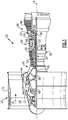
- FIG. 1 schematically illustrates a gas turbine engine 20.
- the gas turbine engine 20 is disclosed herein as a two-spool turbofan that generally incorporates a fan section 22, a compressor section 24, a combustor section 26 and a turbine section 28.
- the fan section 22 drives air along a bypass flow path B in a bypass duct defined within a nacelle 15, and also drives air along a core flow path C for compression and communication into the combustor section 26 then expansion through the turbine section 28.
- FIG. 1 schematic
- the exemplary engine 20 generally includes a low speed spool 30 and a high speed spool 32 mounted for rotation about an engine central longitudinal axis A relative to an engine static structure 36 via several bearing systems 38. It should be understood that various bearing systems 38 at various locations may alternatively or additionally be provided, and the location of bearing systems 38 may be varied as appropriate to the application.
- the low speed spool 30 generally includes an inner shaft 40 that interconnects a fan 42, a first (or low) pressure compressor 44 and a first (or low) pressure turbine 46.
- the inner shaft 40 is connected to the fan 42 through a speed change mechanism, which in exemplary gas turbine engine 20 is illustrated as a geared architecture 48 to drive the fan 42 at a lower speed than the low speed spool 30.
- the high speed spool 32 includes an outer shaft 50 that interconnects a second (or high) pressure compressor 52 and a second (or high) pressure turbine 54.
- a combustor 56 is arranged in exemplary gas turbine 20 between the high pressure compressor 52 and the high pressure turbine 54.
- a mid-turbine frame 57 of the engine static structure 36 is arranged generally between the high pressure turbine 54 and the low pressure turbine 46.
- the mid-turbine frame 57 further supports bearing systems 38 in the turbine section 28.
- the inner shaft 40 and the outer shaft 50 are concentric and rotate via bearing systems 38 about the engine central longitudinal axis A which is collinear with their longitudinal axes.
- the core airflow is compressed by the low pressure compressor 44 then the high pressure compressor 52, mixed and burned with fuel in the combustor 56, then expanded over the high pressure turbine 54 and low pressure turbine 46.
- the mid-turbine frame 57 includes airfoils 59 which are in the core airflow path C.
- the turbines 46, 54 rotationally drive the respective low speed spool 30 and high speed spool 32 in response to the expansion.
- gear system 48 may be located aft of combustor section 26 or even aft of turbine section 28, and fan section 22 may be positioned forward or aft of the location of gear system 48.
- the engine 20 in one example is a high-bypass geared aircraft engine.
- the engine 20 bypass ratio is greater than about six (6), with an example embodiment being greater than about ten (10)
- the geared architecture 48 is an epicyclic gear train, such as a planetary gear system or other gear system, with a gear reduction ratio of greater than about 2.3
- the low pressure turbine 46 has a pressure ratio that is greater than about five.
- the engine 20 bypass ratio is greater than about ten (10:1)
- the fan diameter is significantly larger than that of the low pressure compressor 44
- the low pressure turbine 46 has a pressure ratio that is greater than about five 5:1.
- Low pressure turbine 46 pressure ratio is pressure measured prior to inlet of low pressure turbine 46 as related to the pressure at the outlet of the low pressure turbine 46 prior to an exhaust nozzle.
- the geared architecture 48 may be an epicycle gear train, such as a planetary gear system or other gear system, with a gear reduction ratio of greater than about 2.3:1. It should be understood, however, that the above parameters are only exemplary of one embodiment of a geared architecture engine and that the present invention is applicable to other gas turbine engines including direct drive turbofans.
- the fan section 22 of the engine 20 is designed for a particular flight condition -- typically cruise at about 0.8 Mach and about 35,000 feet (10,668 meters).
- the flight condition of 0.8 Mach and 35,000 ft (10,668 meters), with the engine at its best fuel consumption - also known as "bucket cruise Thrust Specific Fuel Consumption ('TSFC')" - is the industry standard parameter of lbm of fuel being burned divided by lbf of thrust the engine produces at that minimum point.
- "Low fan pressure ratio” is the pressure ratio across the fan blade alone, without a Fan Exit Guide Vane (“FEGV”) system.
- the low fan pressure ratio as disclosed herein according to one non-limiting embodiment is less than about 1.45.
- the "Low corrected fan tip speed” as disclosed herein according to one non-limiting embodiment is less than about 1150 ft / second (350.5 meters/second).
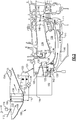
- FIG. 2 shows an intercooled cooling air system 100.
- a high pressure compressor 102 is provided with a tap 104 for tapping air to be utilized as cooling air.
- the tap 104 is from an intermediate location in the high pressure compressor. In alternative embodiments, the tap could be from a low pressure compressor.
- the tap in the Figure 2 embodiment is from a location upstream of a downstream most location 105 in the high pressure compressor 102.
- the tapped air at line 104 passes through a first leg 106 of a heat exchanger and back into a second leg 108 where it is returned through an inner housing 109.
- the heat exchanger 106/108 sits in a chamber 110 in this embodiment, which is radially inward of the bypass duct B.
- a valve 112 selectively allows the air from bypass duct B to pass over the heat exchanger 106/108.
- a control 114 is shown controlling the position of the valve 112. Air at line 116 inward of the housing 109 passes through a shutoff valve 118 into a cooling compressor 120.
- the cooling compressor 120 is provided with a drive 121.
- a system to stop the cooling compressor 120 from compressing is provided.
- the system is a clutch 122 which can disconnect the cooling compressor 120 from its drive 121.
- the drive 121 could be an electric motor and simply stopped.
- the control 114 controls the shutoff valve 118 and the clutch 122. It is desirable that the control be programmed such that the compression of air by the cooling compressor 120 is effectively stopped before the valve 118 is shut down to block the flow of air from line 116 reaching the cooling compressor 120.
- the air Downstream of the cooling compressor 120, the air passes into a line 124 and through struts 128 in a diffuser 126 radially into a mixing chamber 130.
- high pressure air may be tapped at 132 into the mixing chamber 130.
- the high pressure air tapped 132 may be air downstream of the downstream most location 105 in the high pressure compressor 102.
- the air from the mixing chamber 130 is shown passing to cool a disk and rim 142 of a downstream most location in the high pressure compressor 102.
- the air is also shown passing between a fixed housing 136 and a rotating shaft portion 140, which is part of the high pressure spool as described with regard to Figure 1 .
- a chamber 141 between the housing 136 and outer periphery of the shaft portion 140 receives the cooling airflow. That air passes through a tangential on-board injector 144 ("TOBI”) and then passes to cool the first stage blade 146 and vane 148 of a high pressure turbine.
- TOBI tangential on-board injector
- the wall 136 is radially inward of a combustor 134 and a chamber 138 is intermediate to the two.
- the chamber 138 receives air downstream of the downstream most location in the high pressure compressor and, thus, is at high temperature. As the air passes to the TOBI 144 and through the chamber 141, it may be heated by those high temperatures, which reduces the efficiency of the overall system.
- an insulation feature is placed both on at least a majority of the surface area of the housing 136 between the diffuser 126 and the TOBI 144.
- An insulation material is also placed along the majority of the outer surface of the shaft portion 140 between the downstream most location of the high pressure compressor and the rotation of the first turbine blade 146.
- each of the housing 136 and shaft 140 are formed of an underlying base metal and an outer insulation material.
- the outer insulation material has better resistance to heat passage than does the underlying metal.
- Insulation in a gas turbine and as may be defined in this application is a non-structural addition to a structure in that there is little or no structural contribution to the additional aspect involved. Further, the insulation in a gas turbine, may prevent fluid from passing on one side of the lower conductivity material which is sometimes referred to as "infiltration.” Such fluid passage would dramatically lower the value of the measures taken to apply the insulation. And, finally, the insulation may be introduced to the assembly by additional manufacturing steps and processes.
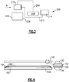
- the cooling system 200 taps air from a location at or downstream of the downstream most location 204 in the high pressure compressor 202.
- the air is shown tapped at 206 from a chamber radially outward of the combustor 208. That air passes through a heat exchanger 210, which is shown schematically being cooled, and then returned back inwardly through chamber 212 to the high pressure turbine 214.
- Such passage of air may also include the wall 136 and shaft 140 as in the Figure 2 embodiment.
- the same temperature challenges are raised.
- Figure 4 shows details of one embodiment of insulation material.
- the outer surface of the shaft 140 which faces the wall 136, is preferably provided with an insulation coating. Coating is preferred for the rotating structure as the attachment of sheets or other structure which might require mechanical attachment raises challenges with the centrifugal forces that the rotating structure will see.
- the underlying base metal 150 is provided with a metallic bond coat 152.
- a thermally-grown oxide coating 154 is placed outwardly of the bond coat 152.
- a ceramic topcoat 156 then surrounds the thermally-grown oxide.
- the ceramic topcoat 156 is composed of Yttria-stabilized zirconia.
- An outer surface of the housing 136 includes the metallic base layer 160 and a double wall structure, such as provided by an attached outer wall 164, which faces the rotating shaft surface 140.
- An intermediate insulation material such as a ceramic fiber blanket 162 is placed between the walls 160 and 164.
- Ceramic fiber blankets are known for various applications and may be formed of bulk fibers produced by spinning processes.
- the blanket 162 may be formed from pure alumina-silica. Further, the blanket 162 may be a continuous blanket and may be mechanically sewn with double needles to provide better integrity to the surface on both sides of the blanket.
- the pipes and, particularly, those downstream of the heat exchanger 106/108 (or 210) may also be provided with insulation. This would include connections 116 and, in particular, connection 124.
- monitors are provided to ensure proper operation of valve 112, valve 118, clutch 122, and predetermine any undesirable pressures or temperatures in the conduit 124.
- a gas turbine engine includes rotatable components including components within a compressor section and a turbine section housed within an outer housing.
- a tap is connected to tap air that has passed at least partially through the compressor section.
- the tap is connected to pass through a heat exchanger and connected to pass into a flow path between a rotating surface and a non-rotating surface.
- the flow path is connected to cool at least one of said rotatable components.
- At least a portion of each of the non-rotating surface and the rotating surface are provided with a base metal, and an insulation material on a surface facing the other of the rotatable and non-rotatable surfaces.
Landscapes
- Engineering & Computer Science (AREA)
- Chemical & Material Sciences (AREA)
- Combustion & Propulsion (AREA)
- Mechanical Engineering (AREA)
- General Engineering & Computer Science (AREA)
- Physics & Mathematics (AREA)
- Fluid Mechanics (AREA)
- Structures Of Non-Positive Displacement Pumps (AREA)
Applications Claiming Priority (1)
| Application Number | Priority Date | Filing Date | Title |
|---|---|---|---|
| US201862653647P | 2018-04-06 | 2018-04-06 |
Publications (2)
| Publication Number | Publication Date |
|---|---|
| EP3550106A1 true EP3550106A1 (de) | 2019-10-09 |
| EP3550106B1 EP3550106B1 (de) | 2024-10-09 |
Family
ID=66092077
Family Applications (1)
| Application Number | Title | Priority Date | Filing Date |
|---|---|---|---|
| EP19167088.4A Active EP3550106B1 (de) | 2018-04-06 | 2019-04-03 | Kühlluft für gasturbinenmotor mit thermisch isolierter kühlluftführung |
Country Status (2)
| Country | Link |
|---|---|
| US (3) | US11428121B2 (de) |
| EP (1) | EP3550106B1 (de) |
Families Citing this family (2)
| Publication number | Priority date | Publication date | Assignee | Title |
|---|---|---|---|---|
| US11021981B2 (en) * | 2018-05-22 | 2021-06-01 | Raytheon Technologies Corporation | Downstream turbine vane cooling for a gas turbine engine |
| EP4450781A1 (de) * | 2023-04-18 | 2024-10-23 | RTX Corporation | Gasturbinentriebwerk konfiguriert für verminderte diffusorwandverwirbelungen und dazugehöriges montageverfahren |
Citations (5)
| Publication number | Priority date | Publication date | Assignee | Title |
|---|---|---|---|---|
| GB2348466A (en) * | 1999-03-27 | 2000-10-04 | Rolls Royce Plc | Gas turbine engine rotor or casing with high or low emissivity surface finish. |
| US6612114B1 (en) * | 2000-02-29 | 2003-09-02 | Daimlerchrysler Ag | Cooling air system for gas turbine |
| EP1956215A2 (de) * | 2007-02-06 | 2008-08-13 | General Electric Company | Gasturbine mit thermisch isoliertem Kühlkreislauf |
| EP2224113A2 (de) * | 2009-02-27 | 2010-09-01 | General Electric Company | Isothermanlieferung einer abkühlenden Flüssigkeit durch einen Durchgang |
| US20130205790A1 (en) * | 2012-02-15 | 2013-08-15 | United Technologies Corporation | Multi-lobed cooling hole and method of manufacture |
Family Cites Families (21)
| Publication number | Priority date | Publication date | Assignee | Title |
|---|---|---|---|---|
| US5783315A (en) * | 1997-03-10 | 1998-07-21 | General Electric Company | Ti-Cr-Al protective coatings for alloys |
| US7288328B2 (en) * | 2004-10-29 | 2007-10-30 | General Electric Company | Superalloy article having a gamma-prime nickel aluminide coating |
| JP2006307733A (ja) * | 2005-04-28 | 2006-11-09 | Mitsubishi Heavy Ind Ltd | ガスタービン排気ディフューザ |
| US7942117B2 (en) | 2006-05-27 | 2011-05-17 | Robinson Thomas C | Engine |
| US7416790B2 (en) * | 2006-12-08 | 2008-08-26 | General Electric Company | Coating systems containing rhodium aluminide-based layers |
| US8056345B2 (en) | 2007-06-13 | 2011-11-15 | United Technologies Corporation | Hybrid cooling of a gas turbine engine |
| US9157325B2 (en) * | 2012-02-27 | 2015-10-13 | United Technologies Corporation | Buffer cooling system providing gas turbine engine architecture cooling |
| US10167723B2 (en) | 2014-06-06 | 2019-01-01 | United Technologies Corporation | Thermally isolated turbine section for a gas turbine engine |
| US10415478B2 (en) | 2015-01-20 | 2019-09-17 | United Technologies Corporation | Air mixing systems having mixing chambers for gas turbine engines |
| US9856793B2 (en) | 2015-02-12 | 2018-01-02 | United Technologies Corporation | Intercooled cooling air with improved air flow |
| US9869204B2 (en) * | 2015-03-06 | 2018-01-16 | United Technologies Corporation | Integrated inner case heat shield |
| US9850819B2 (en) | 2015-04-24 | 2017-12-26 | United Technologies Corporation | Intercooled cooling air with dual pass heat exchanger |
| EP3109550B1 (de) | 2015-06-19 | 2019-09-04 | Rolls-Royce Corporation | Turbinengekühlte kühlluft strömend durch eine rohranordnung |
| JP5932121B1 (ja) * | 2015-09-15 | 2016-06-08 | 三菱日立パワーシステムズ株式会社 | ガスタービンプラント及び既設ガスタービンプラントの改良方法 |
| US10280841B2 (en) * | 2015-12-07 | 2019-05-07 | United Technologies Corporation | Baffle insert for a gas turbine engine component and method of cooling |
| US10260422B2 (en) | 2016-05-06 | 2019-04-16 | United Technologies Corporation | Heat temperature gradient heat exchanger |
| US20180058228A1 (en) * | 2016-08-26 | 2018-03-01 | Barson Composites Corporation | Hot corrosion-resistant coatings for gas turbine components |
| FR3058469B1 (fr) * | 2016-11-09 | 2020-08-21 | Safran | Piece de turbomachine revetue d'une barriere thermique et procede pour l'obtenir |
| JP6856364B2 (ja) * | 2016-11-30 | 2021-04-07 | 三菱重工業株式会社 | ガスタービン用高温部品、ガスタービンの翼及びガスタービン |
| JP6775428B2 (ja) * | 2017-01-12 | 2020-10-28 | 三菱パワー株式会社 | 分割環表面側部材、分割環支持側部材、分割環、静止側部材ユニット及び方法 |
| US10961850B2 (en) * | 2017-09-19 | 2021-03-30 | General Electric Company | Rotatable torque frame for gas turbine engine |
-
2019
- 2019-04-03 EP EP19167088.4A patent/EP3550106B1/de active Active
- 2019-04-05 US US16/375,892 patent/US11428121B2/en active Active
-
2022
- 2022-08-15 US US17/887,869 patent/US11920485B2/en active Active
-
2023
- 2023-11-09 US US18/505,408 patent/US20240076999A1/en active Pending
Patent Citations (5)
| Publication number | Priority date | Publication date | Assignee | Title |
|---|---|---|---|---|
| GB2348466A (en) * | 1999-03-27 | 2000-10-04 | Rolls Royce Plc | Gas turbine engine rotor or casing with high or low emissivity surface finish. |
| US6612114B1 (en) * | 2000-02-29 | 2003-09-02 | Daimlerchrysler Ag | Cooling air system for gas turbine |
| EP1956215A2 (de) * | 2007-02-06 | 2008-08-13 | General Electric Company | Gasturbine mit thermisch isoliertem Kühlkreislauf |
| EP2224113A2 (de) * | 2009-02-27 | 2010-09-01 | General Electric Company | Isothermanlieferung einer abkühlenden Flüssigkeit durch einen Durchgang |
| US20130205790A1 (en) * | 2012-02-15 | 2013-08-15 | United Technologies Corporation | Multi-lobed cooling hole and method of manufacture |
Also Published As
| Publication number | Publication date |
|---|---|
| EP3550106B1 (de) | 2024-10-09 |
| US11428121B2 (en) | 2022-08-30 |
| US20240076999A1 (en) | 2024-03-07 |
| US11920485B2 (en) | 2024-03-05 |
| US20220389836A1 (en) | 2022-12-08 |
| US20200141270A1 (en) | 2020-05-07 |
Similar Documents
| Publication | Publication Date | Title |
|---|---|---|
| US11236675B2 (en) | Gas turbine engine with intercooled cooling air and turbine drive | |
| EP3584427B1 (de) | Zwischengekühltes kühlluftsystem mit niedrigtemperaturluft für lagerkammer | |
| EP3369911B1 (de) | Hitzeschild für gasturbinenmotordiffusorgehäuse | |
| US20240076999A1 (en) | Cooling air for gas turbine engine with thermally isolated cooling air delivery | |
| US11773742B2 (en) | Cooled cooling air for blade air seal through outer chamber | |
| EP3401511B1 (de) | Weiterverwendung und modulierte kühlung von einem spitzenspielregelungssystem für gasturbinenmotoren | |
| EP3575574B1 (de) | Wärmemanagement einer gasturbinenmotorwelle | |
| EP3330515B1 (de) | Gasturbinenmotor | |
| EP3572645B1 (de) | Verbesserte nachgeschaltete turbinenschaufelkühlung für einen gasturbinenmotor | |
| EP3401512A2 (de) | Spitzenspielregelung für einen gasturbinenmotor | |
| EP3388637B1 (de) | Kühlluftkammer für äussere schaufelluftdichtung | |
| EP3388625B1 (de) | Gekühlte kühlluft zur schaufelaussenluftabdichtung durch eine statorschaufel | |
| EP3358152B1 (de) | Externe mischkammer für einen gasturbinenmotor mit gekühlter turbinenkühlluft | |
| US10458332B2 (en) | Cooled gas turbine engine cooling air with cold air dump |
Legal Events
| Date | Code | Title | Description |
|---|---|---|---|
| PUAI | Public reference made under article 153(3) epc to a published international application that has entered the european phase |
Free format text: ORIGINAL CODE: 0009012 |
|
| STAA | Information on the status of an ep patent application or granted ep patent |
Free format text: STATUS: THE APPLICATION HAS BEEN PUBLISHED |
|
| AK | Designated contracting states |
Kind code of ref document: A1 Designated state(s): AL AT BE BG CH CY CZ DE DK EE ES FI FR GB GR HR HU IE IS IT LI LT LU LV MC MK MT NL NO PL PT RO RS SE SI SK SM TR |
|
| AX | Request for extension of the european patent |
Extension state: BA ME |
|
| STAA | Information on the status of an ep patent application or granted ep patent |
Free format text: STATUS: REQUEST FOR EXAMINATION WAS MADE |
|
| 17P | Request for examination filed |
Effective date: 20200330 |
|
| RBV | Designated contracting states (corrected) |
Designated state(s): AL AT BE BG CH CY CZ DE DK EE ES FI FR GB GR HR HU IE IS IT LI LT LU LV MC MK MT NL NO PL PT RO RS SE SI SK SM TR |
|
| STAA | Information on the status of an ep patent application or granted ep patent |
Free format text: STATUS: EXAMINATION IS IN PROGRESS |
|
| 17Q | First examination report despatched |
Effective date: 20220302 |
|
| GRAP | Despatch of communication of intention to grant a patent |
Free format text: ORIGINAL CODE: EPIDOSNIGR1 |
|
| STAA | Information on the status of an ep patent application or granted ep patent |
Free format text: STATUS: GRANT OF PATENT IS INTENDED |
|
| INTG | Intention to grant announced |
Effective date: 20240430 |
|
| RAP1 | Party data changed (applicant data changed or rights of an application transferred) |
Owner name: RTX CORPORATION |
|
| RIN1 | Information on inventor provided before grant (corrected) |
Inventor name: SNAPE, NATHAN Inventor name: SCHWARZ, FREDERICK M. |
|
| GRAS | Grant fee paid |
Free format text: ORIGINAL CODE: EPIDOSNIGR3 |
|
| GRAA | (expected) grant |
Free format text: ORIGINAL CODE: 0009210 |
|
| STAA | Information on the status of an ep patent application or granted ep patent |
Free format text: STATUS: THE PATENT HAS BEEN GRANTED |
|
| AK | Designated contracting states |
Kind code of ref document: B1 Designated state(s): AL AT BE BG CH CY CZ DE DK EE ES FI FR GB GR HR HU IE IS IT LI LT LU LV MC MK MT NL NO PL PT RO RS SE SI SK SM TR |
|
| REG | Reference to a national code |
Ref country code: CH Ref legal event code: EP |
|
| REG | Reference to a national code |
Ref country code: DE Ref legal event code: R096 Ref document number: 602019059933 Country of ref document: DE |
|
| REG | Reference to a national code |
Ref country code: IE Ref legal event code: FG4D |
|
| REG | Reference to a national code |
Ref country code: LT Ref legal event code: MG9D |
|
| REG | Reference to a national code |
Ref country code: NL Ref legal event code: MP Effective date: 20241009 |
|
| REG | Reference to a national code |
Ref country code: AT Ref legal event code: MK05 Ref document number: 1730790 Country of ref document: AT Kind code of ref document: T Effective date: 20241009 |
|
| PG25 | Lapsed in a contracting state [announced via postgrant information from national office to epo] |
Ref country code: NL Free format text: LAPSE BECAUSE OF FAILURE TO SUBMIT A TRANSLATION OF THE DESCRIPTION OR TO PAY THE FEE WITHIN THE PRESCRIBED TIME-LIMIT Effective date: 20241009 |
|
| PG25 | Lapsed in a contracting state [announced via postgrant information from national office to epo] |
Ref country code: NL Free format text: LAPSE BECAUSE OF FAILURE TO SUBMIT A TRANSLATION OF THE DESCRIPTION OR TO PAY THE FEE WITHIN THE PRESCRIBED TIME-LIMIT Effective date: 20241009 |
|
| PG25 | Lapsed in a contracting state [announced via postgrant information from national office to epo] |
Ref country code: HR Free format text: LAPSE BECAUSE OF FAILURE TO SUBMIT A TRANSLATION OF THE DESCRIPTION OR TO PAY THE FEE WITHIN THE PRESCRIBED TIME-LIMIT Effective date: 20241009 Ref country code: IS Free format text: LAPSE BECAUSE OF FAILURE TO SUBMIT A TRANSLATION OF THE DESCRIPTION OR TO PAY THE FEE WITHIN THE PRESCRIBED TIME-LIMIT Effective date: 20250209 Ref country code: PT Free format text: LAPSE BECAUSE OF FAILURE TO SUBMIT A TRANSLATION OF THE DESCRIPTION OR TO PAY THE FEE WITHIN THE PRESCRIBED TIME-LIMIT Effective date: 20250210 |
|
| PG25 | Lapsed in a contracting state [announced via postgrant information from national office to epo] |
Ref country code: FI Free format text: LAPSE BECAUSE OF FAILURE TO SUBMIT A TRANSLATION OF THE DESCRIPTION OR TO PAY THE FEE WITHIN THE PRESCRIBED TIME-LIMIT Effective date: 20241009 |
|
| PG25 | Lapsed in a contracting state [announced via postgrant information from national office to epo] |
Ref country code: BG Free format text: LAPSE BECAUSE OF FAILURE TO SUBMIT A TRANSLATION OF THE DESCRIPTION OR TO PAY THE FEE WITHIN THE PRESCRIBED TIME-LIMIT Effective date: 20241009 |
|
| PG25 | Lapsed in a contracting state [announced via postgrant information from national office to epo] |
Ref country code: ES Free format text: LAPSE BECAUSE OF FAILURE TO SUBMIT A TRANSLATION OF THE DESCRIPTION OR TO PAY THE FEE WITHIN THE PRESCRIBED TIME-LIMIT Effective date: 20241009 |
|
| PG25 | Lapsed in a contracting state [announced via postgrant information from national office to epo] |
Ref country code: NO Free format text: LAPSE BECAUSE OF FAILURE TO SUBMIT A TRANSLATION OF THE DESCRIPTION OR TO PAY THE FEE WITHIN THE PRESCRIBED TIME-LIMIT Effective date: 20250109 |
|
| PG25 | Lapsed in a contracting state [announced via postgrant information from national office to epo] |
Ref country code: LV Free format text: LAPSE BECAUSE OF FAILURE TO SUBMIT A TRANSLATION OF THE DESCRIPTION OR TO PAY THE FEE WITHIN THE PRESCRIBED TIME-LIMIT Effective date: 20241009 Ref country code: GR Free format text: LAPSE BECAUSE OF FAILURE TO SUBMIT A TRANSLATION OF THE DESCRIPTION OR TO PAY THE FEE WITHIN THE PRESCRIBED TIME-LIMIT Effective date: 20250110 Ref country code: AT Free format text: LAPSE BECAUSE OF FAILURE TO SUBMIT A TRANSLATION OF THE DESCRIPTION OR TO PAY THE FEE WITHIN THE PRESCRIBED TIME-LIMIT Effective date: 20241009 |
|
| PG25 | Lapsed in a contracting state [announced via postgrant information from national office to epo] |
Ref country code: PL Free format text: LAPSE BECAUSE OF FAILURE TO SUBMIT A TRANSLATION OF THE DESCRIPTION OR TO PAY THE FEE WITHIN THE PRESCRIBED TIME-LIMIT Effective date: 20241009 |
|
| PG25 | Lapsed in a contracting state [announced via postgrant information from national office to epo] |
Ref country code: RS Free format text: LAPSE BECAUSE OF FAILURE TO SUBMIT A TRANSLATION OF THE DESCRIPTION OR TO PAY THE FEE WITHIN THE PRESCRIBED TIME-LIMIT Effective date: 20250109 |
|
| PG25 | Lapsed in a contracting state [announced via postgrant information from national office to epo] |
Ref country code: SM Free format text: LAPSE BECAUSE OF FAILURE TO SUBMIT A TRANSLATION OF THE DESCRIPTION OR TO PAY THE FEE WITHIN THE PRESCRIBED TIME-LIMIT Effective date: 20241009 |
|
| PGFP | Annual fee paid to national office [announced via postgrant information from national office to epo] |
Ref country code: DE Payment date: 20250319 Year of fee payment: 7 |
|
| PG25 | Lapsed in a contracting state [announced via postgrant information from national office to epo] |
Ref country code: DK Free format text: LAPSE BECAUSE OF FAILURE TO SUBMIT A TRANSLATION OF THE DESCRIPTION OR TO PAY THE FEE WITHIN THE PRESCRIBED TIME-LIMIT Effective date: 20241009 |
|
| REG | Reference to a national code |
Ref country code: DE Ref legal event code: R097 Ref document number: 602019059933 Country of ref document: DE |
|
| PG25 | Lapsed in a contracting state [announced via postgrant information from national office to epo] |
Ref country code: EE Free format text: LAPSE BECAUSE OF FAILURE TO SUBMIT A TRANSLATION OF THE DESCRIPTION OR TO PAY THE FEE WITHIN THE PRESCRIBED TIME-LIMIT Effective date: 20241009 |
|
| PG25 | Lapsed in a contracting state [announced via postgrant information from national office to epo] |
Ref country code: RO Free format text: LAPSE BECAUSE OF FAILURE TO SUBMIT A TRANSLATION OF THE DESCRIPTION OR TO PAY THE FEE WITHIN THE PRESCRIBED TIME-LIMIT Effective date: 20241009 |
|
| PG25 | Lapsed in a contracting state [announced via postgrant information from national office to epo] |
Ref country code: SK Free format text: LAPSE BECAUSE OF FAILURE TO SUBMIT A TRANSLATION OF THE DESCRIPTION OR TO PAY THE FEE WITHIN THE PRESCRIBED TIME-LIMIT Effective date: 20241009 |
|
| PG25 | Lapsed in a contracting state [announced via postgrant information from national office to epo] |
Ref country code: CZ Free format text: LAPSE BECAUSE OF FAILURE TO SUBMIT A TRANSLATION OF THE DESCRIPTION OR TO PAY THE FEE WITHIN THE PRESCRIBED TIME-LIMIT Effective date: 20241009 |
|
| PG25 | Lapsed in a contracting state [announced via postgrant information from national office to epo] |
Ref country code: IT Free format text: LAPSE BECAUSE OF FAILURE TO SUBMIT A TRANSLATION OF THE DESCRIPTION OR TO PAY THE FEE WITHIN THE PRESCRIBED TIME-LIMIT Effective date: 20241009 |
|
| PLBE | No opposition filed within time limit |
Free format text: ORIGINAL CODE: 0009261 |
|
| STAA | Information on the status of an ep patent application or granted ep patent |
Free format text: STATUS: NO OPPOSITION FILED WITHIN TIME LIMIT |
|
| PG25 | Lapsed in a contracting state [announced via postgrant information from national office to epo] |
Ref country code: SE Free format text: LAPSE BECAUSE OF FAILURE TO SUBMIT A TRANSLATION OF THE DESCRIPTION OR TO PAY THE FEE WITHIN THE PRESCRIBED TIME-LIMIT Effective date: 20241009 |
|
| 26N | No opposition filed |
Effective date: 20250710 |
|
| REG | Reference to a national code |
Ref country code: CH Ref legal event code: H13 Free format text: ST27 STATUS EVENT CODE: U-0-0-H10-H13 (AS PROVIDED BY THE NATIONAL OFFICE) Effective date: 20251125 |
|
| PG25 | Lapsed in a contracting state [announced via postgrant information from national office to epo] |
Ref country code: LU Free format text: LAPSE BECAUSE OF NON-PAYMENT OF DUE FEES Effective date: 20250403 |
|
| PG25 | Lapsed in a contracting state [announced via postgrant information from national office to epo] |
Ref country code: MC Free format text: LAPSE BECAUSE OF FAILURE TO SUBMIT A TRANSLATION OF THE DESCRIPTION OR TO PAY THE FEE WITHIN THE PRESCRIBED TIME-LIMIT Effective date: 20241009 |
|
| REG | Reference to a national code |
Ref country code: BE Ref legal event code: MM Effective date: 20250430 |
|
| PG25 | Lapsed in a contracting state [announced via postgrant information from national office to epo] |
Ref country code: BE Free format text: LAPSE BECAUSE OF NON-PAYMENT OF DUE FEES Effective date: 20250430 |
|
| PG25 | Lapsed in a contracting state [announced via postgrant information from national office to epo] |
Ref country code: CH Free format text: LAPSE BECAUSE OF NON-PAYMENT OF DUE FEES Effective date: 20250430 |
|
| PGFP | Annual fee paid to national office [announced via postgrant information from national office to epo] |
Ref country code: GB Payment date: 20260319 Year of fee payment: 8 |
|
| PG25 | Lapsed in a contracting state [announced via postgrant information from national office to epo] |
Ref country code: IE Free format text: LAPSE BECAUSE OF NON-PAYMENT OF DUE FEES Effective date: 20250403 |
|
| PGFP | Annual fee paid to national office [announced via postgrant information from national office to epo] |
Ref country code: FR Payment date: 20260319 Year of fee payment: 8 |