EP1172534A2 - Abgaskrümmer - Google Patents
Abgaskrümmer Download PDFInfo
- Publication number
- EP1172534A2 EP1172534A2 EP01112211A EP01112211A EP1172534A2 EP 1172534 A2 EP1172534 A2 EP 1172534A2 EP 01112211 A EP01112211 A EP 01112211A EP 01112211 A EP01112211 A EP 01112211A EP 1172534 A2 EP1172534 A2 EP 1172534A2
- Authority
- EP
- European Patent Office
- Prior art keywords
- sheet metal
- exhaust manifold
- exhaust
- flange
- mounting flange
- Prior art date
- Legal status (The legal status is an assumption and is not a legal conclusion. Google has not performed a legal analysis and makes no representation as to the accuracy of the status listed.)
- Withdrawn
Links
Images
Classifications
-
- F—MECHANICAL ENGINEERING; LIGHTING; HEATING; WEAPONS; BLASTING
- F01—MACHINES OR ENGINES IN GENERAL; ENGINE PLANTS IN GENERAL; STEAM ENGINES
- F01N—GAS-FLOW SILENCERS OR EXHAUST APPARATUS FOR MACHINES OR ENGINES IN GENERAL; GAS-FLOW SILENCERS OR EXHAUST APPARATUS FOR INTERNAL-COMBUSTION ENGINES
- F01N13/00—Exhaust or silencing apparatus characterised by constructional features
- F01N13/08—Other arrangements or adaptations of exhaust conduits
- F01N13/10—Other arrangements or adaptations of exhaust conduits of exhaust manifolds
-
- F—MECHANICAL ENGINEERING; LIGHTING; HEATING; WEAPONS; BLASTING
- F01—MACHINES OR ENGINES IN GENERAL; ENGINE PLANTS IN GENERAL; STEAM ENGINES
- F01N—GAS-FLOW SILENCERS OR EXHAUST APPARATUS FOR MACHINES OR ENGINES IN GENERAL; GAS-FLOW SILENCERS OR EXHAUST APPARATUS FOR INTERNAL-COMBUSTION ENGINES
- F01N2450/00—Methods or apparatus for fitting, inserting or repairing different elements
- F01N2450/22—Methods or apparatus for fitting, inserting or repairing different elements by welding or brazing
-
- Y—GENERAL TAGGING OF NEW TECHNOLOGICAL DEVELOPMENTS; GENERAL TAGGING OF CROSS-SECTIONAL TECHNOLOGIES SPANNING OVER SEVERAL SECTIONS OF THE IPC; TECHNICAL SUBJECTS COVERED BY FORMER USPC CROSS-REFERENCE ART COLLECTIONS [XRACs] AND DIGESTS
- Y10—TECHNICAL SUBJECTS COVERED BY FORMER USPC
- Y10T—TECHNICAL SUBJECTS COVERED BY FORMER US CLASSIFICATION
- Y10T29/00—Metal working
- Y10T29/49—Method of mechanical manufacture
- Y10T29/4935—Heat exchanger or boiler making
- Y10T29/49389—Header or manifold making
Definitions
- the invention relates to an exhaust manifold with a single Exhaust outlet with outlet mounting flange and at least two Exhaust inlets with inlet mounting flange for mounting on an engine block of a motor vehicle.
- Exhaust manifolds of the aforementioned type are according to the state of the Technology formed by a manifold, which input pipe sections depending on the number of engine cylinders to be connected and has an outlet pipe section which is connected with downstream Components of the exhaust system such as a catalytic converter connected is.
- the manifold can be one piece Tin deep-drawn part or composed of individual tubes and in particular be welded together. You also know manifolds in half-shell technology, which are folded together using a longitudinal fold are connected.
- the manifold can be single-walled or double-walled, i.e. with air gap insulation be, for example according to DE 199 52 648.
- the invention has for its object an exhaust manifold to provide the aforementioned type, which is extremely simple and is still functional.
- the essence of the invention is that the exhaust duct of the exhaust manifold between inlet mounting flange and outlet mounting flange through a single-walled one that forms a manifold Sheet metal hood is formed, the sheet metal hood all Surrounds exhaust gas inlets together.
- the sheet metal hood can be on the side of the exhaust outlet radial flange closed on the circumference or a radial extension include, the or with the outlet mounting flange preferably by welding firmly and gas-tight connected is.
- the sheet metal hood on the side of the exhaust gas inlets an encasing radial flange enclosing all exhaust gas inlets or a common envelope radial extension own the one with the inlet mounting flange preferably by welding firmly and is connected in a gas-tight manner.
- the sheet metal hood has recesses that stabilize the shape and / or bulges, the indentations are preferably in the area between the exhaust gas inlets.
- the sheet metal hood is a particularly simple variant of the invention integrally formed. It can be made from a flat sheet metal plate as a semi-finished product around a mandrel or the like in their complex Final shape to be curved.
- the sheet metal hood can also alternatively consist of two sheet-shaped ones Half shells exist, which overlap with one another Connection flange are interconnected.
- the connecting flange can be at least simply folded over be gas-sealing sheet metal fold.
- the two half-shells can with respect to the connection level of the connecting flange is mirror-inverted his.
- the inlet mounting flange and the outlet mounting flange arranged at right angles to each other Fastening plates with through holes for fastening on the engine block using bolts.
- an exhaust manifold with a simple Outer skin in the form of a sheet metal hood proposed in an assembly on the engine block of the motor vehicle, the cylinder outlet openings covers without forming a single tube itself.
- the sheet metal hood or outer skin is single-walled.
- the Exhaust manifold of the type according to the invention is a simplest sheet metal manifold and can be called a "primitive manifold" are, nevertheless, sufficiently functional and the exhaust gases from the various exhaust ports on the cylinder head collects and conducts into a discharge pipe. It follows significant weight and material savings. The manufacturing cost are small.
- a downstream catalyst shows an improved light-off behavior due to reduced mass of the exhaust manifold.
- the exhaust manifold according to the invention is Suitable for all gasoline and diesel engines and versatile. It can be especially inexpensive in large numbers finished.
- the complex final shape of the sheet metal skin can with Look at a favorable flow behavior, noise minimization, great dimensional stability and sufficient thermal load capacity for a specific engine unit determined by experiment with a certain power become.
- the shape is bent or shaped into the final shape Sheet skin on its own may not be very special dimensionally stable. However, the dimensional stability occurs when the sheet metal skin firmly with the additional stabilizing end flanges welded or otherwise by, for example Sticking or toxins is connected.
- a longitudinal fold in two-part Half-shells as sheet metal skin further increase the dimensional stability, as well as stiffening ribs, indentations, bulges and the like, especially the bent ones Welding edges in the area of the end flanges.
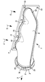
- an exhaust manifold 1 comprises a single one Exhaust outlet 2 with outlet mounting flange 3 and three exhaust inlets 4, 5, 6 with an inlet mounting flange 7 for attachment to an engine block of a motor vehicle.
- the exhaust duct of the exhaust manifold 1 between the inlet mounting flange 7 and outlet mounting flange 3 is through a single-walled sheet metal hood forming a collecting line 8 formed, the sheet metal hood 8 all exhaust gas inlets 4, 5, 6 encloses together.
- the sheet metal hood 8 comprises on the side of the exhaust gas outlet 2 a radial flange closed on the circumference or one Radial extension 9, the or with the outlet mounting flange 3 fixed by welding 14 and gas-tight connected is.
- the sheet metal hood 8 also has on the side of the exhaust gas inlets 4, 5, 6 enclosing all exhaust gas inlets Wrapping radial flange or a common wrapping radial extension 10, the one with the inlet mounting flange 7 also by welding 15, preferably connected by laser welding, firmly and gas-tight is.
- the sheet metal hood 8 contains form-stabilizing indentations 11 in the area between the exhaust gas inlets 4, 5, 6 above and below as shown in the drawing.
- the sheet metal hood can be formed in one piece.
- the sheet metal hood 1 is off two half-shells formed, which overlap with one another Connecting flange 12 are interconnected, the one folded sheet metal is simply.
- the two half-shells are in relation to the connection level of the connecting flange 12 is a mirror image.
- the inlet mounting flange 7 and the outlet mounting flange 3 are, as is per se prior art, mounting plates arranged at right angles to each other.
- the Fastening plates have through bores 13, via the exhaust manifold 1 on the engine block using bolts can be attached.
Landscapes
- Engineering & Computer Science (AREA)
- Chemical & Material Sciences (AREA)
- Combustion & Propulsion (AREA)
- Mechanical Engineering (AREA)
- General Engineering & Computer Science (AREA)
- Exhaust Silencers (AREA)
Abstract
Description
Claims (10)
- Abgaskrümmer (1) mit einem einzigen Abgasauslaß (2) mit Auslaß-Befestigungsflansch (3) und zumindest zwei Abgaseinlässen (4, 5, 6) mit Einlaß-Befestigungsflansch (7) für eine Befestigung an einem Motorblock eines Kraftfahrzeuges,
dadurch gekennzeichnet, daß die Abgasführung des Abgaskrümmers (1) zwischen Einlaß-Befestigungsflansch (7) und Auslaß-Befestigungsflansch (3) durch eine einwandige, eine Sammelleitung ausbildende Blechhaube (8) gebildet ist, wobei die Blechhaube (8) sämtliche Abgaseinlässe (4, 5, 6) gemeinsam umschließt. - Abgaskrümmer nach Anspruch 1,
dadurch gekennzeichnet, daß die Blechhaube (8) auf der Seite des Abgasauslasses (2) einen auf dem Umfang geschlossenen Radialflansch bzw. eine Radialerweiterung (9) umfaßt, der bzw. die mit dem Auslaß-Befestigungsflansch (3) vorzugsweise durch Verschweißung (14) fest und gasabdichtend verbunden ist. - Abgaskrümmer nach Anspruch 1 oder 2,
dadurch gekennzeichnet, daß die Blechhaube (8) auf der Seite der Abgaseinlässe (4, 5, 6) einen sämtliche Abgaseinlässe umschließenden Umhüllungs-Radialflansch bzw. eine gemeinsame Umhüllungs-Radialerweiterung (10) umfaßt, der bzw. die mit dem Einlaß-Befestigungsflansch (7) vorzugsweise durch Verschweißung (15) fest und gasabdichtend verbunden ist. - Abgaskrümmer nach einem der Ansprüche 1 bis 3,
dadurch gekennzeichnet, daß die Blechhaube (8) formstabilisierende Einbuchtungen (11) und/oder Ausbeulungen aufweist. - Abgaskrümmer nach Anspruch 4,
dadurch gekennzeichnet, daß die formstabilisierenden Einbuchtungen (11) im Bereich zwischen den Abgaseinlässen (4, 5, 6) gelegen sind. - Abgaskrümmer nach einem der Ansprüche 1 bis 5,
dadurch gekennzeichnet, daß die Blechhaube einstückig ausgebildet ist. - Abgaskrümmer nach einem der Ansprüche 1 bis 5,
dadurch gekennzeichnet, daß die Blechhaube (1) aus zwei Halbschalen besteht, welche über einen deckungsgleichen Verbindungsflansch (12) miteinander verbunden sind. - Abgaskrümmer nach Anspruch 7,
dadurch gekennzeichnet, daß der Verbindungsflansch (12) ein zumindest einfach umgeschlagener Blechfalz ist. - Abgaskrümmer nach Anspruch 7 oder 8,
dadurch gekennzeichnet, daß die beiden Halbschalen bezüglich der Verbindungsebene des Verbindungsflansches (12) spiegelbildlich gleich ausgebildet sind. - Abgaskrümmer nach einem der Ansprüche 1 bis 9,
dadurch gekennzeichnet, daß der Einlaß-Befestigungsflansch (7) und der Auslaß-Befestigungsflansch (3) rechtwinklig zueinander angeordnete Befestigungsplatten mit Durchgangsbohrungen (13) für eine Befestigung am Motorblock mittels Schraubbolzen sind.
Applications Claiming Priority (2)
| Application Number | Priority Date | Filing Date | Title |
|---|---|---|---|
| DE10034538A DE10034538A1 (de) | 2000-07-15 | 2000-07-15 | Abgaskrümmer |
| DE10034538 | 2000-07-15 |
Publications (2)
| Publication Number | Publication Date |
|---|---|
| EP1172534A2 true EP1172534A2 (de) | 2002-01-16 |
| EP1172534A3 EP1172534A3 (de) | 2004-01-07 |
Family
ID=7649104
Family Applications (1)
| Application Number | Title | Priority Date | Filing Date |
|---|---|---|---|
| EP01112211A Withdrawn EP1172534A3 (de) | 2000-07-15 | 2001-05-18 | Abgaskrümmer |
Country Status (3)
| Country | Link |
|---|---|
| US (1) | US6474697B2 (de) |
| EP (1) | EP1172534A3 (de) |
| DE (1) | DE10034538A1 (de) |
Cited By (1)
| Publication number | Priority date | Publication date | Assignee | Title |
|---|---|---|---|---|
| EP2333265A1 (de) * | 2009-12-14 | 2011-06-15 | Benteler Automobiltechnik GmbH | Abgaskrümmer mit Leitblech |
Families Citing this family (6)
| Publication number | Priority date | Publication date | Assignee | Title |
|---|---|---|---|---|
| US7096583B2 (en) * | 2002-09-09 | 2006-08-29 | Leen David Steed | System and method of producing exhaust and other types of manifold |
| KR100525424B1 (ko) * | 2003-09-18 | 2005-11-02 | 엘지전자 주식회사 | 열교환기용 냉매 분배기와 그 제조방법 |
| FR2873747B1 (fr) * | 2004-07-29 | 2006-11-03 | Faurecia Sys Echappement | Collecteur d'echappement |
| DE102007007638A1 (de) * | 2007-02-16 | 2008-08-21 | Daimler Ag | Brennkraftmaschine mit mehreren Brennräumen |
| US8356411B2 (en) | 2008-04-07 | 2013-01-22 | Benteler Automotive Corporation | Exhaust manifold with hybrid construction and method |
| EP3436752B1 (de) | 2016-03-30 | 2021-06-30 | Marine Canada Acquisition Inc. | Fahrzeugheizgerät und steuerungen dafür |
Family Cites Families (27)
| Publication number | Priority date | Publication date | Assignee | Title |
|---|---|---|---|---|
| US1327311A (en) * | 1919-04-25 | 1920-01-06 | Ralph C Chesnutt | Manifold for internal-combustion engines |
| US2713195A (en) * | 1951-03-15 | 1955-07-19 | Solar Aircraft Co | Method of making an engine manifold |
| FR1553867A (de) * | 1967-11-17 | 1969-01-17 | ||
| US3667432A (en) * | 1970-05-04 | 1972-06-06 | Mack Trucks | Engine air manifold |
| DE2530800A1 (de) * | 1975-07-10 | 1977-01-27 | Volkswagenwerk Ag | Verbindungsleitung innerhalb einer auspuffanlage eines kraftfahrzeuges |
| IT1188883B (it) * | 1979-09-06 | 1988-01-28 | Zeuna Staerker Kg | Collettore per motori alternativi a combustione interna |
| IT1188884B (it) * | 1979-09-06 | 1988-01-28 | Zeuna Staerker Kg | Collettore in particolare per un motore a sei cilindri in linea |
| US4372112A (en) * | 1980-07-01 | 1983-02-08 | Ford Motor Company | Thin-walled exhaust gas manifold casting |
| US4537027A (en) * | 1983-11-21 | 1985-08-27 | Apx Group, Inc. | Hybrid exhaust manifold |
| US4779415A (en) * | 1986-11-26 | 1988-10-25 | Arvin Industries, Inc. | Manifold tuning structure |
| US4777708A (en) * | 1987-03-17 | 1988-10-18 | Ap Industries, Inc. | Method for manufacturing an exhaust manifold |
| US5134852A (en) * | 1990-08-23 | 1992-08-04 | Tennessee Gas Pipeline Company | Clam shell type Y-joint |
| US5327722A (en) * | 1993-08-09 | 1994-07-12 | Ap Parts Manufacturing Company | Stamp formed connector for achieving equal length exhaust pipes |
| US5768890A (en) * | 1993-11-12 | 1998-06-23 | Benteler Automotive Corporation | Exhaust air rail manifold |
| DE19505710C2 (de) * | 1994-02-21 | 2002-10-17 | Aisin Takaoka Ltd | Auspuffkrümmer |
| FR2727466B1 (fr) * | 1994-11-25 | 1997-01-17 | Renault | Collecteur d'echappement pour moteur a combustion interne |
| US6247552B1 (en) * | 1994-12-16 | 2001-06-19 | J. Eberspächer Gmbh & Co. | Air gap-insulated exhaust manifold |
| DE19511514C1 (de) * | 1995-03-29 | 1996-08-01 | Daimler Benz Ag | Abgaskrümmer für eine Brennkraftmaschine |
| ES2112592T3 (es) * | 1995-09-28 | 1998-04-01 | Benteler Werke Ag | Codo para gases de escape. |
| DE19627299A1 (de) * | 1996-07-06 | 1998-01-08 | Eberspaecher J Gmbh & Co | Schalldämpfer mit Außen- und Innenhalbschalen |
| JPH1026037A (ja) * | 1996-07-09 | 1998-01-27 | Yutaka Giken Co Ltd | センサ取付ボス |
| DE19628798B4 (de) * | 1996-07-17 | 2008-04-17 | Daimler Ag | Abgaskrümmer zur Abgasführung aus einer Brennkraftmaschine |
| JP3446493B2 (ja) * | 1996-09-13 | 2003-09-16 | トヨタ自動車株式会社 | エキゾーストマニホルド |
| EP0849445B1 (de) * | 1996-12-20 | 2001-11-14 | Zeuna-Stärker Gmbh & Co Kg | Abgassammler und Verfahren zu seiner Herstellung |
| FR2777320B1 (fr) * | 1998-04-09 | 2000-09-22 | Renault | Collecteur d'echappement pour moteur a combustion interne |
| US6264880B1 (en) * | 1998-07-22 | 2001-07-24 | The Regents Of The University Of California | Manifold free multiple sheet superplastic forming |
| DE19952648C2 (de) * | 1998-10-23 | 2001-12-20 | Leistritz Abgastech | Luftspaltisolierter Schalenkrümmer |
-
2000
- 2000-07-15 DE DE10034538A patent/DE10034538A1/de not_active Withdrawn
-
2001
- 2001-05-18 EP EP01112211A patent/EP1172534A3/de not_active Withdrawn
- 2001-07-13 US US09/905,239 patent/US6474697B2/en not_active Expired - Fee Related
Cited By (2)
| Publication number | Priority date | Publication date | Assignee | Title |
|---|---|---|---|---|
| EP2333265A1 (de) * | 2009-12-14 | 2011-06-15 | Benteler Automobiltechnik GmbH | Abgaskrümmer mit Leitblech |
| US8549851B2 (en) | 2009-12-14 | 2013-10-08 | Benteler Automobiltechnik Gmbh | Exhaust manifold with baffle plate |
Also Published As
| Publication number | Publication date |
|---|---|
| DE10034538A1 (de) | 2002-01-24 |
| US6474697B2 (en) | 2002-11-05 |
| EP1172534A3 (de) | 2004-01-07 |
| US20020017786A1 (en) | 2002-02-14 |
Similar Documents
| Publication | Publication Date | Title |
|---|---|---|
| EP2955344B1 (de) | Schalldämpfer | |
| EP1104839B1 (de) | Abgasanlage für ein Kraftfahrzeug, Kraftfahrzeug und Verfahren zur Herstellung einer Abgasanlage | |
| DE69105882T2 (de) | Schalldämpfer für Motoren. | |
| EP2718550B1 (de) | Schalldämpfer und herstellungsverfahren | |
| EP0676535A1 (de) | Katalysator für die katalytische Behandlung von Abgas | |
| EP1450017B1 (de) | Anordnung zur Überführung der Abgase eines Verbrennungsmotors in eine Abgasleitung | |
| EP1475522B1 (de) | Kombinierte Abgasnachbehandlungs-/Schalldämpfungsvorrichtung im Abgasstrang einer Brennkraftmaschine | |
| DE69728891T3 (de) | Schalldämpfer für strömende gase | |
| DE4444760C2 (de) | Luftspaltisolierter Abgaskrümmer | |
| EP2333265A1 (de) | Abgaskrümmer mit Leitblech | |
| DE10034538A1 (de) | Abgaskrümmer | |
| EP3198197B1 (de) | Heizgerät-abgasrohranordnung mit integriertem schalldämpfer und herstellungsverfahren dafür | |
| DE102010052938A1 (de) | Abgaseinrichtung für Quermotor | |
| EP1243455B1 (de) | Luftführungskanal für ein Kraftfahrzeug | |
| EP1012455B1 (de) | Katalytischer konverter für einen kleinmotor | |
| EP1109994B1 (de) | Vorrichtung zur strömungsberuhigung in der abgasleitung eines verbrennungsmotors | |
| EP1375848B1 (de) | Vorrichtung zur Reduzierung von Schallemissionen und Verfahren zur Herstellung einer solchen Vorrichtung | |
| DE112020002964T5 (de) | Auslasssystem und Schalldämpfer | |
| WO2001051336A1 (de) | Bodengruppe eines kraftfahrzeugs | |
| DE3704006C2 (de) | ||
| EP1416148A2 (de) | Schallreduzierendes Bauteil für ein Luftführungsrohr | |
| DE10008458B4 (de) | Abgassystem für ein Motorrad | |
| DE4431484C2 (de) | Schalldämpfer mit integrierter Abgasreinigungsstufe | |
| EP0925984B1 (de) | Abgasanlage für ein Kraftfahrzeug sowie Kraftfahrzeug mit einer Abgasanlage | |
| EP1225315B1 (de) | Verfahren zur Herstellung eines Abgassammlers |
Legal Events
| Date | Code | Title | Description |
|---|---|---|---|
| PUAI | Public reference made under article 153(3) epc to a published international application that has entered the european phase |
Free format text: ORIGINAL CODE: 0009012 |
|
| AK | Designated contracting states |
Kind code of ref document: A2 Designated state(s): AT BE CH CY DE DK ES FI FR GB GR IE IT LI LU MC NL PT SE TR |
|
| AX | Request for extension of the european patent |
Free format text: AL;LT;LV;MK;RO;SI |
|
| RAP1 | Party data changed (applicant data changed or rights of an application transferred) |
Owner name: J. EBERSPAECHER GMBH & CO. KG |
|
| PUAL | Search report despatched |
Free format text: ORIGINAL CODE: 0009013 |
|
| AK | Designated contracting states |
Kind code of ref document: A3 Designated state(s): AT BE CH CY DE DK ES FI FR GB GR IE IT LI LU MC NL PT SE TR |
|
| AX | Request for extension of the european patent |
Extension state: AL LT LV MK RO SI |
|
| 17P | Request for examination filed |
Effective date: 20040707 |
|
| AKX | Designation fees paid |
Designated state(s): AT BE CH CY DE DK ES FI FR GB GR IE IT LI LU MC NL PT SE TR |
|
| STAA | Information on the status of an ep patent application or granted ep patent |
Free format text: STATUS: THE APPLICATION IS DEEMED TO BE WITHDRAWN |
|
| 18D | Application deemed to be withdrawn |
Effective date: 20060719 |