EP1171703B1 - Steuervorrichtung für stellantriebe einer brennkraftmaschine - Google Patents
Steuervorrichtung für stellantriebe einer brennkraftmaschine Download PDFInfo
- Publication number
- EP1171703B1 EP1171703B1 EP00931003A EP00931003A EP1171703B1 EP 1171703 B1 EP1171703 B1 EP 1171703B1 EP 00931003 A EP00931003 A EP 00931003A EP 00931003 A EP00931003 A EP 00931003A EP 1171703 B1 EP1171703 B1 EP 1171703B1
- Authority
- EP
- European Patent Office
- Prior art keywords
- control units
- control
- control unit
- actuators
- control device
- Prior art date
- Legal status (The legal status is an assumption and is not a legal conclusion. Google has not performed a legal analysis and makes no representation as to the accuracy of the status listed.)
- Expired - Lifetime
Links
Images

Classifications
-
- F—MECHANICAL ENGINEERING; LIGHTING; HEATING; WEAPONS; BLASTING
- F02—COMBUSTION ENGINES; HOT-GAS OR COMBUSTION-PRODUCT ENGINE PLANTS
- F02D—CONTROLLING COMBUSTION ENGINES
- F02D41/00—Electrical control of supply of combustible mixture or its constituents
- F02D41/30—Controlling fuel injection
- F02D41/3005—Details not otherwise provided for
-
- F—MECHANICAL ENGINEERING; LIGHTING; HEATING; WEAPONS; BLASTING
- F01—MACHINES OR ENGINES IN GENERAL; ENGINE PLANTS IN GENERAL; STEAM ENGINES
- F01L—CYCLICALLY OPERATING VALVES FOR MACHINES OR ENGINES
- F01L9/00—Valve-gear or valve arrangements actuated non-mechanically
- F01L9/20—Valve-gear or valve arrangements actuated non-mechanically by electric means
-
- F—MECHANICAL ENGINEERING; LIGHTING; HEATING; WEAPONS; BLASTING
- F02—COMBUSTION ENGINES; HOT-GAS OR COMBUSTION-PRODUCT ENGINE PLANTS
- F02D—CONTROLLING COMBUSTION ENGINES
- F02D41/00—Electrical control of supply of combustible mixture or its constituents
- F02D41/02—Circuit arrangements for generating control signals
- F02D41/14—Introducing closed-loop corrections
- F02D41/1401—Introducing closed-loop corrections characterised by the control or regulation method
- F02D2041/1413—Controller structures or design
- F02D2041/1418—Several control loops, either as alternatives or simultaneous
- F02D2041/1419—Several control loops, either as alternatives or simultaneous the control loops being cascaded, i.e. being placed in series or nested
Definitions
- the invention relates to a control device for actuators an internal combustion engine.
- a control device for actuators is known from EP 0 493 634 A1 an internal combustion engine known.
- the actuators are electromagnetic actuators, which act as actuators Gas exchange valves are assigned.
- the control device comprises a control unit, the control signals for all actuators generated and the sensor signals evaluated.
- the Control signals must be generated with a high temporal resolution be, with computation-intensive control and regulation algorithms must be used to make a very fast and to ensure precise opening and closing of the gas exchange valves and at the same time a low noise emission ensured by the electromagnetic actuator.
- the control unit also controls the injection valves, who meter fuel.
- the known control device has the disadvantage that a single control unit does not provides the necessary computing power for the computationally intensive Control algorithms among the required Perform real-time conditions. It was therefore proposed to provide the control device with several control units, the respective control signals for subsets of the actuators produce.
- U.S.-A-4,486,829 describes e.g. three computers with data and tax Lines are connected, with at least one of the three computers being able to control the other two, which is given in the prior art by the fact that each of the three modules n, 1 or 2 the bus connection of its two neighbors can control.
- Monitoring signals (minor loop check signals) exchanged.
- the signals from e.g. Module 2 off, is in module 1 (and Module n) detected an error in module 2.
- Resetting a faulty Module / computer happens here with a mechanism that is internal to everyone individual computer is triggered without reset signals from the outside be processed.
- the monitoring of the actuators and the control units is an essential prerequisite for a safe and low-emission Operation of the internal combustion engine.
- the object of the invention is a control device for To create actuators of an internal combustion engine that simple is and at the same time safe operation of the internal combustion engine guaranteed.
- the invention is characterized in that the control units, which are available for controlling actuators, at the same time to ensure that they function correctly monitor.
- the control units which are available for controlling actuators, at the same time to ensure that they function correctly monitor.
- Control units in the form of a ring with monitoring lines connected with each other. This will monitor everyone Control units with very little wiring guaranteed.
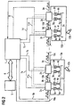
- a control device ( Figure 1) comprises a higher-level Control unit 1 and several control units 2a, 2b, 2c, 2d, which are electrically connected to actuators 3a to h are.
- the actuators are preferably as actuators Gas exchange valves 4a to h assigned.
- the actuators 3a to h comprise at least one electromagnet with one Coil and a core and an anchor that matches the respective Gas exchange valve 4a to h is coupled.
- the actuators preferably have two electromagnets, the armature by appropriate control of the coils the electromagnet is brought into contact with one of the contact surfaces can be and thus the actuation of the gas exchange valves he follows.
- the actuators 3a to d, 4e to h are also one cylinder assigned to the internal combustion engine.
- They are Actuators 3a to d and gas exchange valves 4a to d one assigned the first cylinder Z1 of the internal combustion engine while the actuators 3e to h and gas exchange valves 4e to h one fourth cylinder Z4 assigned to the internal combustion engine are.
- Two gas exchange valves 4a, b and 4e, f; 4c, d and 4g, h are on the inlet side and on the outlet side, respectively of the respective cylinder Z1, Z4 arranged.
- the gas exchange valves 4a, b, d, e can thus also be used as intake valves and Gas exchange valves 4c, d and 4g, h also referred to as exhaust valves become.
- the number of intake and exhaust valves can be depending on the embodiment of the internal combustion engine his.
- the control unit 2a is for the actuators 3a, 3b for the Inlet valves of the first cylinder Z1 are provided while the Control unit 2b for the actuators 3c, d the exhaust valves of the first cylinder is provided.
- An engine control device 5 is provided which is dependent the speed N of the crankshaft of the internal combustion engine, a size that represents the driver's request, such as B. the pedal value of an accelerator pedal sensor and possibly other Sizes, such as a mass air flow in the intake tract Internal combustion engine or a temperature of the internal combustion engine air drawn in or from an exhaust gas probe detected exhaust gas composition the operation of the internal combustion engine controls.
- the engine control device controls 5 for example, injectors or spark plugs.
- the motor control device 5 calculates the desired one Opening of the respective gas exchange valves 4a to h and the desired opening time based on the crankshaft angle.
- the engine control device 5 is via a first data bus 6 connected to the higher-level control unit 1.
- the first data bus is preferably a CAN bus (controller area Network) trained.
- the engine control device 5 and the higher-level control unit exchange via the first data bus 6 data from. So the higher-level control unit receives 1 from the motor control device 5, which are calculated by this Time periods and opening starts of the gas exchange valves 4a to d. Furthermore, the engine control device sends the higher-level Control unit also the current crankshaft angle the crankshaft of the internal combustion engine.
- the parent Control unit 1 thus takes over the communication with the engine control device 5.
- the higher-level Control device 1 calculates depending on the crankshaft angle and the specified opening times and opening times Timing signals for the control units 2a to d. As a result, the control units 2a to d are separated from the communication tasks kept clear with the engine control unit.
- the computing capacity of the control units 2a to d is available almost completely for the control of the actuators 3a to d are available.
- the higher-level control unit 1 is via communication lines 7a, b, c, d connected to the control units 2a to d.
- the higher-level control unit 1 generates timing signals for the respective control units 2a to d that they are about transmits the communication lines 7a to d.
- the timing signals are in the higher-level control facility 1 depending on the crankshaft angle, the opening of the respective gas exchange valve 4a to h and the associated Opening time determined.
- Preferably for each control unit 2a to d generates a timing signal.
- the timing signal is, for example, a square wave signal in which the falling flank the closing and the rising flank the Opening of the associated valve indicates.
- the communication lines 7a to d are preferably unidirectional Signal transmission from the higher-level control unit the control units 2a to d.
- the control units 2a to d generate control signals around the armature quickly to the desired position, i.e. to the to bring the first or second contact surface in order to achieve a gentle To ensure that the anchor is attached.
- This is preferable a digital one in each of the control units 2a to d Processor provided the corresponding control or regulation programs processed and thereby the control signals for the actuators 3a to d generated.
- the position is controlled in each case the armature of the actuators 3a to d. In the case of regulation the position is preferably provided as a controlled variable. Alternatively, however, one that is characteristic of the position can also be used Size can be provided as a control variable, such as. B. the current or flow through one of the coils of the electromagnet the actuators 3a to d.
- the control units 2a to d also monitor the Actuators 3a to d. For example, based on the recorded Actuator armature position detected whether the Anchor undesirable due to the bias of the return means of the actuator certain rest position dropped and there is a fault in the actuator.
- the Control units (2a-d) are via a second data bus 11 connected to the higher-level control unit 1.
- the control units report the respective state of the actuators 3a to d and a possible failure of one of the actuators this bus to the higher-level control device.
- the control units 2a to d and the higher-level control unit 1 are ring-shaped with monitoring lines 9a to e connected.
- the control units 2a to d and the higher-level control unit 1 also with a ring Reset lines 10a to e connected.
- Each control unit 2a to d and the higher-level control unit checks whether on its input side Monitoring line 9a to e the monitoring signal is applied.
- the reset lines are preferably arranged and trained that data transmission over the reset lines in the opposite direction to the transmission of the monitoring signal takes place in the monitoring lines 9a.
- the monitoring signal from the control unit 2a transmitted to the control unit 2b. provides the control unit 2b determines that the monitoring signal is not or transmitted incorrectly, it preferably causes as an error response, the transmission of a reset signal via the reset line 10b to the Control unit 2a.
- the reset line 10b is on a reset input the control unit 2a out. If at the reset input control unit 2a receives a reset signal, the control unit 2a is in a predetermined initialization state reset.
- the Power supply to the control unit 2a is briefly interrupted and all computer programs and any existing electronic Elements like a microprocessor and an oscillator initialized.
- the presence of a reset signal on the respective Input of the reset line 10c, d, e, a also has in the other control units 2b, c, d and the parent Control unit 1 has the same effect as the control unit 2a.
- the higher-level control unit 1 with the control units 2a to d connects. If one of the control units 2a to d recognize an error of another control unit, so it generates a feedback signal that goes through the feedback line 11 is transmitted to the higher-level control unit.
- the higher-level control unit 1 can then via the second Query data bus 8 which of the control units 2a to d in is an error condition and then resetting the corresponding one Initiate control unit. Alternatively, it can be in the If a feedback signal is present on the feedback line also all or a subset of the control units 2a reset to d.
- the provision of the reset lines 10a to e has the advantage that if a control unit error is detected, the control unit, which recognized the error directly the error reaction can execute with effect on the faulty control unit. Error detection and error reaction are therefore decentralized.
- the monitoring signal is preferably a square wave signal with a predetermined one Frequency. Such a square wave signal can be used generate and evaluate low computing effort.
- control units 2a, 2b are the respective control signals generate for the actuators of the first cylinder Z1 via a control line 13a directly to the final stage of a Injector 12a connected to the fuel in the first Cylinder.
- control unit 2b a corresponding error if the control unit 2a detects an error Signal transmitted via the control line 13a, which causes that the fuel metering is interrupted by the injection valve 12a and thus prevents unburned Fuel enters the intake tract of the internal combustion engine.
- This direct access to an output stage of the injection valve 12a has the advantage that when a fault is detected, the The fuel metering is immediately interrupted by the injection valve can be and not only after a time delay, which is due to the transfer of a corresponding one Error message via the first and second data bus 5, 6 to the engine control device 5.
- control units 2c, d are also via a control line 13b connected to the final stage of an injection valve 12b, which meters the fuel into the fourth cylinder 24.
- control unit for example, can also be used the monitoring line 9c is connected to the control unit 2b is, via the control line 13a with the injection valve 12a.
- control units 2a to d can vary depending on the embodiment of the invention vary.
- a Control unit also a different one than in this embodiment Activate the specified number of actuators.
- At least one further higher-level control unit can be, for example, for all intake valves, as well a separate parent for all exhaust valves of the internal combustion engine Control unit can be provided.
- the ring-shaped connection of the higher-level control unit and the control units 2a to d via the monitoring lines is characterized by a small number of required Inputs and outputs at the control units and the higher-level Control unit and a low wiring effort out. However, it is any other kind the wiring of the monitoring lines imaginable.
Landscapes
- Engineering & Computer Science (AREA)
- Mechanical Engineering (AREA)
- General Engineering & Computer Science (AREA)
- Chemical & Material Sciences (AREA)
- Combustion & Propulsion (AREA)
- Combined Controls Of Internal Combustion Engines (AREA)
- Valve Device For Special Equipments (AREA)
- Output Control And Ontrol Of Special Type Engine (AREA)
- Electrical Control Of Air Or Fuel Supplied To Internal-Combustion Engine (AREA)
Description
- Figur 1
- eine erste Ausführungsform einer Steuervorrichtung für Stellantriebe einer Brennkraftmaschine,
- Figur 2
- xeine zweite Ausführungsform der Steuervorrichtung.
Claims (6)
- Steuervorrichtung für Stellantriebe einer Brennkraftmaschinemit mindestens zwei Steuereinheiten (2a, 2b, 2c, 2d), die jeweils Stellsignale erzeugen, mit denen mindestens je ein disjunkter Stellantrieb (3a-h) der Brennkraftmaschine angesteuert wird, und die über Überwachungsleitungen (9a-e) miteinander verbunden sind, undmit einer übergeordneten Steuereinheit (1), die die anderen Steuereinheiten (2a-d) steuert und die ebenfalls über Überwachungsleitungen (9a, 9e) mit mindestens einer Überwachungseinheit (2a-d) verbunden ist, wobei die Steuereinheiten (1, 2a-d) so ausgebildet sind, dass sie ein Überwachungssignal erzeugen, das über eine ausgangsseitige Überwachungsleitung übertragen wird, und die Steuereinheiten (1, 2a-d) ferner so ausgebildet sind, dass sie abhängig von einem über eine eingangsseitige Übertragungsleitung empfangenen Überwachungssignal die fehlerfreie Funktion einer anderen Steuereinheit (1, 2a-d) überwachen, undmit Rücksetzleitungen (10 a-e), über die die Steuereinheiten (1, 2a-d) verbunden sind, und die zum Übertragen von Rücksetzsignalen vorgesehen sind, wobei jeweils eine Steuereinheit (1, 2a-d) Mittel zum Erzeugen der Rücksetzsignale hat, die so ausgebildet sind, dass sie Rücksetzsignale erzeugen, wenn sie eine fehlerhafte Funktion einer anderen Steuereinheit (1, 2a-d) festgestellt haben, und wobei die Steuereinheiten so ausgebildet sind, dass sie bei Empfang eines Rücksetzsignals in einen vorgegebenen Initialisierungszustand zurückgesetzt werden.
- Steuervorrichtung nach Anspruch 1, dadurch gekennzeichnet, daß die Steuereinheiten (1, 2a-d) über Überwachungsleitungen (9a-e) in Form eines Rings miteinander verbunden sind.
- Steuervorrichtung nach einem der vorstehenden Ansprüche, dadurch gekennzeichnet, daß die Steuereinheiten (1, 2a-d) über mindestens eine Rückmeldeleitung (11, 11a, 11b) mit der übergeordneten Steuereinheit (1) verbunden sind, wobei die Rückmeldeleitung (11, 11a, 11b) zum Übertragen von Rückmeldesignalen vorgesehen sind, die jeweils eine Steuereinheit (1, 2a-d) erzeugt, wenn sie eine fehlerhafte Funktion einer anderen Steuereinheit (1, 2a-d) festgestellt hat.
- Steuervorrichtung nach einem der vorstehenden Ansprüche, dadurch gekennzeichnet, daß die Steuereinheiten (1, 2a-d), die Stellsignale zum Steuern von Stellantrieben (3a-h) für Stellglieder genau eines Zylinders (Z1,Z4) der Brennkraftmaschine erzeugen, über weitere Rückmeldeleitungen (11a, 11b) miteinander verbunden sind, die zum Übertragen von Rückmeldesignalen vorgesehen sind, die jeweils eine dieser Steuereinheiten (2a-d) erzeugt, wenn sie eine fehlerhafte Funktion einer anderen dieser Steuereinheiten (2a-d) erkennt.
- Steuervorrichtung nach einem der vorstehenden Ansprüche, dadurch gekennzeichnet, daß zumindest eine Teilmenge der Steuereinheiten (2a-d) Stellsignale zum Steuern von elektromechanischen Stellantrieben erzeugt, denen als Stellglied je ein Gaswechselventil (4a-h) zugeordnet ist.
- Steuervorrichtung nach Anspruch 5, dadurch gekennzeichnet, daß die Steuereinheiten (2a-d), die Stellsignale zum Steuern von elektromechanischen Stellantrieben erzeugen, denen als Stellglied je ein Gaswechselventil (4a-h) zugeordnet ist, über eine Steuerleitung (13a, 13b) einen direkten Durchgriff auf eine Endstufe eines Einspritzventils (12a, 12b) hat.
Applications Claiming Priority (3)
| Application Number | Priority Date | Filing Date | Title |
|---|---|---|---|
| DE19918031 | 1999-04-21 | ||
| DE19918031 | 1999-04-21 | ||
| PCT/DE2000/001017 WO2000065218A1 (de) | 1999-04-21 | 2000-04-03 | Steuervorrichtung für stellantriebe einer brennkraftmaschine |
Publications (2)
| Publication Number | Publication Date |
|---|---|
| EP1171703A1 EP1171703A1 (de) | 2002-01-16 |
| EP1171703B1 true EP1171703B1 (de) | 2004-09-22 |
Family
ID=7905324
Family Applications (1)
| Application Number | Title | Priority Date | Filing Date |
|---|---|---|---|
| EP00931003A Expired - Lifetime EP1171703B1 (de) | 1999-04-21 | 2000-04-03 | Steuervorrichtung für stellantriebe einer brennkraftmaschine |
Country Status (5)
| Country | Link |
|---|---|
| US (1) | US20020072845A1 (de) |
| EP (1) | EP1171703B1 (de) |
| JP (1) | JP2002543327A (de) |
| DE (1) | DE50007910D1 (de) |
| WO (1) | WO2000065218A1 (de) |
Families Citing this family (8)
| Publication number | Priority date | Publication date | Assignee | Title |
|---|---|---|---|---|
| DE10331872A1 (de) * | 2003-07-14 | 2005-02-10 | Robert Bosch Gmbh | Verfahren zur Überwachung eines technischen Systems |
| DE102005003916B4 (de) | 2005-01-27 | 2012-06-06 | Continental Automotive Gmbh | Überwachen der Funktionssicherheit einer Brennkraftmaschine |
| JP4618273B2 (ja) * | 2007-05-25 | 2011-01-26 | トヨタ自動車株式会社 | 内燃機関の制御装置 |
| DE102007054678B3 (de) * | 2007-11-14 | 2009-04-02 | Wago Verwaltungsgesellschaft Mbh | Verfahren zur Erkennung von Störquellen für Automatisierungseinrichtungen und Störquellenerkennungseinheit hierzu |
| EP2307674A1 (de) * | 2008-07-30 | 2011-04-13 | Valeo Systemes De Controle Moteur | Steuereinheit für einen oder mehrere elektromagnetische(n) aktuatoren eines verbrennungsmotorventils und verschiedene anordnungen aus solchen steuereinheiten und solchen elektromagnetischen aktuatoren |
| WO2010130872A1 (en) * | 2009-05-13 | 2010-11-18 | Wärtsilä Finland Oy | Engine fuel supply control |
| JP6057968B2 (ja) * | 2014-10-07 | 2017-01-11 | 三菱重工業株式会社 | エンジン制御システム、車両システム及びエンジン制御方法 |
| SE2050229A1 (en) * | 2020-03-02 | 2021-08-17 | Freevalve Ab | Internal combustion engine comprising a decentralized valve-control arrangement and method therefore |
Family Cites Families (6)
| Publication number | Priority date | Publication date | Assignee | Title |
|---|---|---|---|---|
| JPS57164636A (en) * | 1981-04-03 | 1982-10-09 | Hitachi Ltd | Control method for transmission system |
| JP3043349B2 (ja) | 1989-12-12 | 2000-05-22 | 株式会社いすゞセラミックス研究所 | 電磁力バルブ駆動制御装置 |
| DE69428633T2 (de) * | 1993-06-17 | 2002-06-20 | Denso Corp | Fahrzeugsdiagnosesystem |
| JP3430579B2 (ja) * | 1993-10-05 | 2003-07-28 | 株式会社デンソー | 車両用通信システムの異常検出装置 |
| SE503397C2 (sv) * | 1994-09-11 | 1996-06-03 | Mecel Ab | Arrangemang och förfarande för ett reglersystem till en förbränningsmotor innefattande ett distribuerat datornät |
| DK174249B1 (da) * | 1996-10-28 | 2002-10-14 | Man B & W Diesel As | Flercylindret forbrændingsmotor med elektronisk styresystem |
-
2000
- 2000-04-03 JP JP2000613938A patent/JP2002543327A/ja not_active Withdrawn
- 2000-04-03 EP EP00931003A patent/EP1171703B1/de not_active Expired - Lifetime
- 2000-04-03 DE DE50007910T patent/DE50007910D1/de not_active Expired - Lifetime
- 2000-04-03 WO PCT/DE2000/001017 patent/WO2000065218A1/de active IP Right Grant
-
2001
- 2001-10-22 US US10/033,226 patent/US20020072845A1/en not_active Abandoned
Also Published As
| Publication number | Publication date |
|---|---|
| DE50007910D1 (de) | 2004-10-28 |
| EP1171703A1 (de) | 2002-01-16 |
| WO2000065218A1 (de) | 2000-11-02 |
| US20020072845A1 (en) | 2002-06-13 |
| JP2002543327A (ja) | 2002-12-17 |
Similar Documents
| Publication | Publication Date | Title |
|---|---|---|
| DE4219669A1 (de) | Steuergerät zur Berechnung von Steuergrößen für sich wiederholende Steuervorgänge | |
| WO2003014850A1 (de) | Verfahren und prozessleitsystem zum betrieb einer technischen anlage | |
| EP1171702A1 (de) | Schaltung zur steuerung mindestens eines jeweils elektromechanisch betätigten ein- und auslassventils einer brennkraftmaschine | |
| WO2015071321A1 (de) | Sicherheitssteuerung mit konfigurierbaren eingängen | |
| EP1171703B1 (de) | Steuervorrichtung für stellantriebe einer brennkraftmaschine | |
| DE102007031769B4 (de) | Verfahren zur Überwachung eines Funktionsrechners in einem Steuergerät | |
| EP1642179A1 (de) | Vorrichtung und verfahren zum automatisierten steuern eines betriebsablaufs bei einer technischen anlage | |
| DE10117450A1 (de) | Drosselklappensteuerung für Fahrzeuge unter Nutzung redundanter Drosselsignale | |
| EP1479003B1 (de) | Verfahren und vorrichtung zur steuerung einer funktionseinheit eines kraftfahrzeugs | |
| DE10143454A1 (de) | Fahrzeugsteuereinrichtung | |
| EP2099164B1 (de) | Sicherheitsvorrichtung zur sicheren Ansteuerung angeschlossener Aktoren | |
| DE3316660C2 (de) | ||
| DE102005003916B4 (de) | Überwachen der Funktionssicherheit einer Brennkraftmaschine | |
| EP1222378A1 (de) | Vorrichtung und verfahren zur steuerung einer antriebseinheit | |
| WO2010054874A1 (de) | Verfahren und system zur steuerung einer kommunikation zwischen einem funktionsrechner und einem überwachungsmodul | |
| DE102013108910B4 (de) | Elektromagnetventilsteuervorrichtung | |
| EP1287250A1 (de) | Verfahren zur überprüfung eines kapazitiven stellgliedes | |
| EP3246778B1 (de) | Vorrichtung zum auslesen von daten aus einem sicherheitskritischen steuergerät | |
| DE102005048346A1 (de) | Verfahren zum Betrieb einer Brennkraftmaschine mit einer elektrohydraulischen Ventilsteuerung | |
| WO2002016764A1 (de) | Verfahren zum betreiben einer brennkraftmaschine und entsprechende vorrichtung | |
| DE4322841C2 (de) | Gefahrenmeldeanlage | |
| WO2002052199A1 (de) | Verfahren und vorrichtung zum betrieb einer mehrere komponenten umfassenden technischen anlage, insbesondere einer verbrennungsanlage zum erzeugen von elektrischer energie | |
| DE102009050692B4 (de) | Sicherheits-Kommunikationssystem zur Signalisierung von Systemzuständen | |
| DE19755311B4 (de) | Verfahren und Vorrichtung zur Informationsübertragung in Kraftfahrzeugen | |
| DE10148331A1 (de) | Steuervorrichtung, Datenübertragungssystem und Verfahren zur Steuerung eines Datenbuszugangs eines Datenpakets |
Legal Events
| Date | Code | Title | Description |
|---|---|---|---|
| PUAI | Public reference made under article 153(3) epc to a published international application that has entered the european phase |
Free format text: ORIGINAL CODE: 0009012 |
|
| 17P | Request for examination filed |
Effective date: 20010919 |
|
| AK | Designated contracting states |
Kind code of ref document: A1 Designated state(s): AT BE CH CY DE DK ES FI FR GB GR IE IT LI LU MC NL PT SE |
|
| GRAP | Despatch of communication of intention to grant a patent |
Free format text: ORIGINAL CODE: EPIDOSNIGR1 |
|
| GRAS | Grant fee paid |
Free format text: ORIGINAL CODE: EPIDOSNIGR3 |
|
| GRAA | (expected) grant |
Free format text: ORIGINAL CODE: 0009210 |
|
| AK | Designated contracting states |
Kind code of ref document: B1 Designated state(s): DE FR GB |
|
| REG | Reference to a national code |
Ref country code: GB Ref legal event code: FG4D Free format text: NOT ENGLISH |
|
| REG | Reference to a national code |
Ref country code: IE Ref legal event code: FG4D Free format text: GERMAN |
|
| REF | Corresponds to: |
Ref document number: 50007910 Country of ref document: DE Date of ref document: 20041028 Kind code of ref document: P |
|
| GBT | Gb: translation of ep patent filed (gb section 77(6)(a)/1977) |
Effective date: 20050116 |
|
| REG | Reference to a national code |
Ref country code: IE Ref legal event code: FD4D |
|
| PLBE | No opposition filed within time limit |
Free format text: ORIGINAL CODE: 0009261 |
|
| STAA | Information on the status of an ep patent application or granted ep patent |
Free format text: STATUS: NO OPPOSITION FILED WITHIN TIME LIMIT |
|
| ET | Fr: translation filed | ||
| 26N | No opposition filed |
Effective date: 20050623 |
|
| PGFP | Annual fee paid to national office [announced via postgrant information from national office to epo] |
Ref country code: FR Payment date: 20090414 Year of fee payment: 10 |
|
| PGFP | Annual fee paid to national office [announced via postgrant information from national office to epo] |
Ref country code: GB Payment date: 20090421 Year of fee payment: 10 |
|
| GBPC | Gb: european patent ceased through non-payment of renewal fee |
Effective date: 20100403 |
|
| REG | Reference to a national code |
Ref country code: FR Ref legal event code: ST Effective date: 20101230 |
|
| PG25 | Lapsed in a contracting state [announced via postgrant information from national office to epo] |
Ref country code: GB Free format text: LAPSE BECAUSE OF NON-PAYMENT OF DUE FEES Effective date: 20100403 |
|
| PG25 | Lapsed in a contracting state [announced via postgrant information from national office to epo] |
Ref country code: FR Free format text: LAPSE BECAUSE OF NON-PAYMENT OF DUE FEES Effective date: 20100430 |
|
| PGFP | Annual fee paid to national office [announced via postgrant information from national office to epo] |
Ref country code: DE Payment date: 20180430 Year of fee payment: 19 |
|
| REG | Reference to a national code |
Ref country code: DE Ref legal event code: R119 Ref document number: 50007910 Country of ref document: DE |
|
| PG25 | Lapsed in a contracting state [announced via postgrant information from national office to epo] |
Ref country code: DE Free format text: LAPSE BECAUSE OF NON-PAYMENT OF DUE FEES Effective date: 20191101 |