EP1170525A2 - Auskuppelbare Schwungraddämpfungseinrichtung für Brennkraftmaschinen - Google Patents
Auskuppelbare Schwungraddämpfungseinrichtung für Brennkraftmaschinen Download PDFInfo
- Publication number
- EP1170525A2 EP1170525A2 EP01401814A EP01401814A EP1170525A2 EP 1170525 A2 EP1170525 A2 EP 1170525A2 EP 01401814 A EP01401814 A EP 01401814A EP 01401814 A EP01401814 A EP 01401814A EP 1170525 A2 EP1170525 A2 EP 1170525A2
- Authority
- EP
- European Patent Office
- Prior art keywords
- flywheel
- friction
- primary flywheel
- primary
- linked
- Prior art date
- Legal status (The legal status is an assumption and is not a legal conclusion. Google has not performed a legal analysis and makes no representation as to the accuracy of the status listed.)
- Granted
Links
Images


Classifications
-
- F—MECHANICAL ENGINEERING; LIGHTING; HEATING; WEAPONS; BLASTING
- F16—ENGINEERING ELEMENTS AND UNITS; GENERAL MEASURES FOR PRODUCING AND MAINTAINING EFFECTIVE FUNCTIONING OF MACHINES OR INSTALLATIONS; THERMAL INSULATION IN GENERAL
- F16D—COUPLINGS FOR TRANSMITTING ROTATION; CLUTCHES; BRAKES
- F16D43/00—Automatic clutches
- F16D43/02—Automatic clutches actuated entirely mechanically
- F16D43/04—Automatic clutches actuated entirely mechanically controlled by angular speed
- F16D43/14—Automatic clutches actuated entirely mechanically controlled by angular speed with centrifugal masses actuating the clutching members directly in a direction which has at least a radial component; with centrifugal masses themselves being the clutching members
- F16D43/18—Automatic clutches actuated entirely mechanically controlled by angular speed with centrifugal masses actuating the clutching members directly in a direction which has at least a radial component; with centrifugal masses themselves being the clutching members with friction clutching members
-
- F—MECHANICAL ENGINEERING; LIGHTING; HEATING; WEAPONS; BLASTING
- F16—ENGINEERING ELEMENTS AND UNITS; GENERAL MEASURES FOR PRODUCING AND MAINTAINING EFFECTIVE FUNCTIONING OF MACHINES OR INSTALLATIONS; THERMAL INSULATION IN GENERAL
- F16F—SPRINGS; SHOCK-ABSORBERS; MEANS FOR DAMPING VIBRATION
- F16F15/00—Suppression of vibrations in systems; Means or arrangements for avoiding or reducing out-of-balance forces, e.g. due to motion
- F16F15/10—Suppression of vibrations in rotating systems by making use of members moving with the system
- F16F15/12—Suppression of vibrations in rotating systems by making use of members moving with the system using elastic members or friction-damping members, e.g. between a rotating shaft and a gyratory mass mounted thereon
- F16F15/131—Suppression of vibrations in rotating systems by making use of members moving with the system using elastic members or friction-damping members, e.g. between a rotating shaft and a gyratory mass mounted thereon the rotating system comprising two or more gyratory masses
- F16F15/13128—Suppression of vibrations in rotating systems by making use of members moving with the system using elastic members or friction-damping members, e.g. between a rotating shaft and a gyratory mass mounted thereon the rotating system comprising two or more gyratory masses the damping action being at least partially controlled by centrifugal masses
-
- F—MECHANICAL ENGINEERING; LIGHTING; HEATING; WEAPONS; BLASTING
- F16—ENGINEERING ELEMENTS AND UNITS; GENERAL MEASURES FOR PRODUCING AND MAINTAINING EFFECTIVE FUNCTIONING OF MACHINES OR INSTALLATIONS; THERMAL INSULATION IN GENERAL
- F16F—SPRINGS; SHOCK-ABSORBERS; MEANS FOR DAMPING VIBRATION
- F16F15/00—Suppression of vibrations in systems; Means or arrangements for avoiding or reducing out-of-balance forces, e.g. due to motion
- F16F15/10—Suppression of vibrations in rotating systems by making use of members moving with the system
- F16F15/12—Suppression of vibrations in rotating systems by making use of members moving with the system using elastic members or friction-damping members, e.g. between a rotating shaft and a gyratory mass mounted thereon
- F16F15/131—Suppression of vibrations in rotating systems by making use of members moving with the system using elastic members or friction-damping members, e.g. between a rotating shaft and a gyratory mass mounted thereon the rotating system comprising two or more gyratory masses
- F16F15/13157—Suppression of vibrations in rotating systems by making use of members moving with the system using elastic members or friction-damping members, e.g. between a rotating shaft and a gyratory mass mounted thereon the rotating system comprising two or more gyratory masses with a kinematic mechanism or gear system, e.g. planetary
-
- F—MECHANICAL ENGINEERING; LIGHTING; HEATING; WEAPONS; BLASTING
- F16—ENGINEERING ELEMENTS AND UNITS; GENERAL MEASURES FOR PRODUCING AND MAINTAINING EFFECTIVE FUNCTIONING OF MACHINES OR INSTALLATIONS; THERMAL INSULATION IN GENERAL
- F16F—SPRINGS; SHOCK-ABSORBERS; MEANS FOR DAMPING VIBRATION
- F16F15/00—Suppression of vibrations in systems; Means or arrangements for avoiding or reducing out-of-balance forces, e.g. due to motion
- F16F15/10—Suppression of vibrations in rotating systems by making use of members moving with the system
- F16F15/12—Suppression of vibrations in rotating systems by making use of members moving with the system using elastic members or friction-damping members, e.g. between a rotating shaft and a gyratory mass mounted thereon
- F16F15/131—Suppression of vibrations in rotating systems by making use of members moving with the system using elastic members or friction-damping members, e.g. between a rotating shaft and a gyratory mass mounted thereon the rotating system comprising two or more gyratory masses
- F16F15/139—Suppression of vibrations in rotating systems by making use of members moving with the system using elastic members or friction-damping members, e.g. between a rotating shaft and a gyratory mass mounted thereon the rotating system comprising two or more gyratory masses characterised by friction-damping means
- F16F15/1397—Overload protection, i.e. means for limiting torque
-
- F—MECHANICAL ENGINEERING; LIGHTING; HEATING; WEAPONS; BLASTING
- F16—ENGINEERING ELEMENTS AND UNITS; GENERAL MEASURES FOR PRODUCING AND MAINTAINING EFFECTIVE FUNCTIONING OF MACHINES OR INSTALLATIONS; THERMAL INSULATION IN GENERAL
- F16F—SPRINGS; SHOCK-ABSORBERS; MEANS FOR DAMPING VIBRATION
- F16F15/00—Suppression of vibrations in systems; Means or arrangements for avoiding or reducing out-of-balance forces, e.g. due to motion
- F16F15/10—Suppression of vibrations in rotating systems by making use of members moving with the system
- F16F15/14—Suppression of vibrations in rotating systems by making use of members moving with the system using masses freely rotating with the system, i.e. uninvolved in transmitting driveline torque, e.g. rotative dynamic dampers
Definitions
- the invention relates to a device for reducing the effect of irregularities in the torque supplied by a vehicle heat engine automobile.
- the invention relates more particularly to a device to reduce irregularities in the torque supplied by a motor motor vehicle thermal, of the type in which a steering wheel engine, which is linked to the crankshaft of the engine and which causes a vehicle clutch, is likely to be linked by rotation to the device, in particular to at least one rotary element inertia.
- the increase in total flywheel inertia causes overconsumption of fuel for reports of reduced rank of transmission such as first and second reports.
- a flywheel comprising a device known as a "double damping flywheel” or “DVA”.
- DVA double damping flywheel
- a first steering wheel which is linked at the engine crankshaft, has the highest inertia.
- a second flywheel which is linked to the input shaft of the transmission, is connected to the first steering wheel by elastic means. Beyond the resonant frequency of the device, the second flywheel is highly damped, which reduces irregularities in engine torque downstream of the device.
- This device has the disadvantage, however, due to the presence of the elastic bond between the first and the second steering wheel, to resonate for a particular regime of motor rotation corresponding to starting or stopping the engine.
- the transition from the motor to the resonance regime can jerk when stopping the engine, which can be unpleasant in terms of acoustics, or provoke high angular travel of the first flywheel during starting, especially when it is an extended start in cold weather, which can lead to damage engine and / or transmission mechanics.
- the invention proposes a device of the type described above comprising at least one disengageable inertial rotary element depending on the speed of motor rotation.
- the invention provides a device of the type described previously, characterized in that the rotary inertia element is rotatably mounted coaxially with the flywheel, and in that it is likely to be linked in rotation to the crankshaft via of a centrifugal coupling device in a range determined rotation speed of the motor.
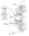
- Figures 1 and 3 show a set of device 10 produced according to the invention.
- such a device 10 is intended for reduce irregularities in the torque supplied by a heat engine 12 of motor vehicle.
- a flywheel 14 which is linked to the crankshaft 16 of the heat engine 12 and which drives a clutch 18, shown here schematically, is likely to be linked in rotation to device 10, that is to say in particular to at least one rotary element 20 of inertia.
- the rotary element 20 of inertia is mounted to rotate coaxially with the flywheel 14, and it is likely to be linked in rotation to the crankshaft 16 by via a centrifugal coupling device 22 in a determined range of motor rotation speeds 12.
- the device 10 includes the flywheel 14. More particularly, the device 10 comprises, from upstream to downstream according to the kinematic order of its elements, i.e. from the right to the left of Figure 1, a primary flywheel 24 which is linked to crankshaft 16, the coaxial coupling device centrifugal 22, and a secondary coaxial flywheel 20, which constitutes the rotary element 20 of inertia.
- the primary flywheel 24 is arranged at the end of the crankshaft 16 to which it is rigidly connected by known means (not shown) such as screws, and bears on its free face 26 the clutch 18, while the rotary element 20 of inertia is crossed by the crankshaft 16 and is therefore arranged between the flywheel primary 24 and the motor 12.
- known means such as screws
- the secondary flywheel 20 forms a bell surrounding the primary flywheel 24.
- the secondary flywheel 20 is for example made using a manufacturing process by molding and / or forging. It has a cylindrical part 28 central including an inner groove 30 receives a bearing 32, by example a single row radial contact ball bearing, which rotates the secondary flywheel 20 on the crankshaft 16.
- the centrifugal coupling device 22 comprises radially expandable means 34 which are arranged inside the bell, between the primary flywheel 24 and the secondary flywheel 20.
- the coupling device centrifugal has a friction disc 36 which is mounted at the interior of the secondary flywheel 20.
- the friction disc 36 is mounted free in axial sliding in the secondary flywheel 20 and it is also linked in rotation to the secondary flywheel 20.
- the friction disc 36 may have on its periphery outer grooves which are complementary to splines 38 arranged in a bore 40 of the secondary flywheel 20.
- the friction disc 36 is pinched axially between a friction face 42 of the primary flywheel 24 and a friction face 44 of a plate 46 which is axially movable inside the bell that forms the secondary flywheel 26 and which is called back to the flywheel primary 24.
- the friction disc 36 is kept pressed against the friction face 42 of the primary flywheel 24 via the friction face 44 of the plate 46, which is returned to the primary flywheel 24 by elastic return means.
- the plate 46 is susceptible to be moved from its position in which it pinches the disc friction 36 by the expanding means 34.
- the movable plate 46 is substantially annular, and it is both held coaxially to the axis C of the device 10 and recalled elastically towards the primary flywheel 24 via a elastic diaphragm 48 on which it is mounted.
- the diaphragm elastic 48 has elastic radial blades 50 which are carried by a hub 52 linked to the primary flywheel 24. The blades 50 are likely to be stressed axially by the means expandable 34 away from the primary flywheel 24 to spread the plate 46 from its pinch position of the disc 36 of friction.
- the friction faces 44 and 42 of the plate mobile 46 and primary flywheel 24 are covered with linings friction.
- the means expandable 34 comprise a series of balls 54 which are prisoners of the radial housings 56 of a cage 58 which is axially mounted between a bearing face 60 of the primary flywheel 24 and the radial blades 50 of the elastic diaphragm 48.
- the balls 54 are likely to move between a radial position of rest close to the axis C of the device and a radial position of centrifugation in which they move away from this axis C.
- the determined range of rotational speeds of the motor 12 in which the device centrifugal coupling 22 is engaged corresponds to a range of the rotational speeds of the motor 12 which are less than a speed threshold value.
- the coupling device centrifugal 22 can therefore be disengaged beyond the value determined engine speed threshold 12.
- the outer ends of the blades 50 elastic radials are closer to the primary flywheel 24 than so are their inner ends. In this way, the blades 50 are supported on the movable plate 46 when the balls 54 are in their radial rest position.
- the balls 54 because of their inertia, are susceptible, beyond a determined value engine speed threshold, to move radially towards the outside in their housings 56 in order to bend the elastic blades 50 of the diaphragm 48 and thus spread axially from its pinch position of the friction disc 36 the plate 46 which is linked to the blades 50.
- stiffness of the elastic blades 50 and the mass of each ball 54 determines the speed threshold value for which the centrifugal coupling device 22 passes from its clutched rest position in its disengaged position.
- This configuration is particularly advantageous because, as part of mass production, it is possible to adapt the threshold speed for which the device 10 is disengaged in accordance with engine specifications 12 considered by choosing a diaphragm 48 whose blades 50 have a determined stiffness and balls 54 of adequate mass.
- Figures 3 and 4 illustrate a second embodiment of the invention in which the expandable means 34 comprise at least two pads 60 integral with the primary flywheel 24, which are arranged radially between the primary flywheel 24 and the flywheel secondary 20, each in the form of a circular arc curvature substantially equal to that of the inner span cylindrical of the secondary flywheel so as to be susceptible engage / disengage the secondary flywheel 20 on the flywheel primary 24 by tightening the cylindrical part 28.
- the expandable means 34 comprise at least two pads 60 integral with the primary flywheel 24, which are arranged radially between the primary flywheel 24 and the flywheel secondary 20, each in the form of a circular arc curvature substantially equal to that of the inner span cylindrical of the secondary flywheel so as to be susceptible engage / disengage the secondary flywheel 20 on the flywheel primary 24 by tightening the cylindrical part 28.
- the outer periphery 62 of the part cylindrical 28 is machined, for example by turning, so to form a friction surface suitable for cooperating with friction ends 64 of the pads 60 which are covered with a friction lining 66.
- each shoe 60 which is opposite to its end 64 of each shoe 60 is pivotally mounted relative to an axis 68 offset from the primary flywheel 24 around which it is recalled by elastic means.
- each shoe 60 is movable between a rest position in which its end 64 is in contact with the cylindrical inner part 28 friction of the secondary flywheel 20 and thus ensures the connection of the secondary flywheel 20 and primary flywheel 24, and a position of centrifugation in which when the speed value of motor rotation is greater than the threshold value, the end 64 of friction of the shoe 60 leaves the internal cylindrical part 28 of the secondary flywheel 20 so as to disengage the flywheel secondary 20 of the primary flywheel 24.
- the elastic return means are, without limitation of the invention, consisting of springs 72 helical torsion.
- the pads 60 due to their inertia, are likely, beyond a determined value of engine speed threshold, pivot around their axes 68 to oppose the restoring force exerted by the springs 72, so that the secondary flywheel 20 is no longer linked to the flywheel primary 24.
- the stiffness of the torsion springs 72 and the mass of each shoe 60 determines the value of the threshold of speed at which the centrifugal coupling device 22 goes from its engaged clutch position to its disengaged position.
- This configuration is particularly advantageous because, as part of mass production, it is possible to adapt the threshold speed for which the device 10 is disengaged in accordance with engine specifications 12 considered by choosing springs 72 of torsional stiffness determined and skids 60 of adequate mass.
- the device 10 makes it possible to benefit from a steering wheel motor comprising a first permanent inertia, which corresponds to the inertia of the primary flywheel 24, and a second disengageable inertia, which corresponds to the inertia of the secondary flywheel 24, which operates only for rotational speeds of the motor 12 whose value is less than that of the threshold speed.
- an engine 12 equipped with such a flywheel 14 has the advantage of providing regular torque at low speed, does joint action of the first and second inertias, and can moreover be relaunched quickly at high speed, since in this case only the first inertia occurs, the secondary flywheel 20 turning crazy on the crankshaft without opposing torque of engine inertia 12.
Landscapes
- Engineering & Computer Science (AREA)
- General Engineering & Computer Science (AREA)
- Mechanical Engineering (AREA)
- Physics & Mathematics (AREA)
- Acoustics & Sound (AREA)
- Aviation & Aerospace Engineering (AREA)
- One-Way And Automatic Clutches, And Combinations Of Different Clutches (AREA)
- Mechanical Operated Clutches (AREA)
Applications Claiming Priority (2)
| Application Number | Priority Date | Filing Date | Title |
|---|---|---|---|
| FR0008892A FR2811392B1 (fr) | 2000-07-07 | 2000-07-07 | Dispositif d'amortissement a inertie debrayable pour moteur thermique |
| FR0008892 | 2000-07-07 |
Publications (3)
| Publication Number | Publication Date |
|---|---|
| EP1170525A2 true EP1170525A2 (de) | 2002-01-09 |
| EP1170525A3 EP1170525A3 (de) | 2003-05-28 |
| EP1170525B1 EP1170525B1 (de) | 2005-11-30 |
Family
ID=8852243
Family Applications (1)
| Application Number | Title | Priority Date | Filing Date |
|---|---|---|---|
| EP01401814A Expired - Lifetime EP1170525B1 (de) | 2000-07-07 | 2001-07-06 | Auskuppelbare Schwungraddämpfungseinrichtung für Brennkraftmaschinen |
Country Status (4)
| Country | Link |
|---|---|
| EP (1) | EP1170525B1 (de) |
| DE (1) | DE60115332T2 (de) |
| ES (1) | ES2249398T3 (de) |
| FR (1) | FR2811392B1 (de) |
Families Citing this family (1)
| Publication number | Priority date | Publication date | Assignee | Title |
|---|---|---|---|---|
| FR2857073B1 (fr) | 2003-07-04 | 2005-08-19 | Eric Antoinon Andre Doremus | Perfectionnement aux volants d'inertie, en particulier pour vehicule automobile |
Citations (8)
| Publication number | Priority date | Publication date | Assignee | Title |
|---|---|---|---|---|
| DE1450208A1 (de) * | 1963-08-30 | 1969-03-27 | Twin Disc Inc | Einrichtung zur Kraftuebertragung |
| US4046240A (en) * | 1975-06-27 | 1977-09-06 | Robert Bosch G.M.B.H. | Centrifugal friction clutch |
| JPS5659056A (en) * | 1979-10-18 | 1981-05-22 | Fuji Heavy Ind Ltd | Flywheel device |
| JPS5761831A (en) * | 1980-10-02 | 1982-04-14 | Akio Makino | Constant speed clutch |
| DE3418671A1 (de) * | 1983-10-24 | 1985-05-09 | LuK Lamellen und Kupplungsbau GmbH, 7580 Bühl | Daempfungseinrichtung zum aufnehmen bzw. ausgleichen von drehstoessen |
| DE3627784A1 (de) * | 1986-08-16 | 1987-07-02 | Daimler Benz Ag | Geteiltes schwungrad |
| EP0592352A2 (de) * | 1992-10-05 | 1994-04-13 | United Technologies Corporation | Fliehkraftkupplung |
| DE19809425A1 (de) * | 1998-03-05 | 1999-09-09 | Volkswagen Ag | Zweimassenschwungrad für eine Brennkraftmaschine |
-
2000
- 2000-07-07 FR FR0008892A patent/FR2811392B1/fr not_active Expired - Fee Related
-
2001
- 2001-07-06 DE DE2001615332 patent/DE60115332T2/de not_active Expired - Fee Related
- 2001-07-06 ES ES01401814T patent/ES2249398T3/es not_active Expired - Lifetime
- 2001-07-06 EP EP01401814A patent/EP1170525B1/de not_active Expired - Lifetime
Patent Citations (8)
| Publication number | Priority date | Publication date | Assignee | Title |
|---|---|---|---|---|
| DE1450208A1 (de) * | 1963-08-30 | 1969-03-27 | Twin Disc Inc | Einrichtung zur Kraftuebertragung |
| US4046240A (en) * | 1975-06-27 | 1977-09-06 | Robert Bosch G.M.B.H. | Centrifugal friction clutch |
| JPS5659056A (en) * | 1979-10-18 | 1981-05-22 | Fuji Heavy Ind Ltd | Flywheel device |
| JPS5761831A (en) * | 1980-10-02 | 1982-04-14 | Akio Makino | Constant speed clutch |
| DE3418671A1 (de) * | 1983-10-24 | 1985-05-09 | LuK Lamellen und Kupplungsbau GmbH, 7580 Bühl | Daempfungseinrichtung zum aufnehmen bzw. ausgleichen von drehstoessen |
| DE3627784A1 (de) * | 1986-08-16 | 1987-07-02 | Daimler Benz Ag | Geteiltes schwungrad |
| EP0592352A2 (de) * | 1992-10-05 | 1994-04-13 | United Technologies Corporation | Fliehkraftkupplung |
| DE19809425A1 (de) * | 1998-03-05 | 1999-09-09 | Volkswagen Ag | Zweimassenschwungrad für eine Brennkraftmaschine |
Non-Patent Citations (1)
| Title |
|---|
| PATENT ABSTRACTS OF JAPAN vol. 006, no. 138 (M-145), 27 juillet 1982 (1982-07-27) & JP 57 061831 A (MAKINO AKIO), 14 avril 1982 (1982-04-14) * |
Also Published As
| Publication number | Publication date |
|---|---|
| ES2249398T3 (es) | 2006-04-01 |
| FR2811392A1 (fr) | 2002-01-11 |
| DE60115332T2 (de) | 2006-06-29 |
| FR2811392B1 (fr) | 2002-11-08 |
| EP1170525B1 (de) | 2005-11-30 |
| DE60115332D1 (de) | 2006-01-05 |
| EP1170525A3 (de) | 2003-05-28 |
Similar Documents
| Publication | Publication Date | Title |
|---|---|---|
| EP2286103B1 (de) | Reibkupplungsvorrichtung mit einem doppelstossdämpfungslenkrad, für das eine sekundäranordnung axial bezüglich einer gegendruckplatte festgelegt angebracht ist | |
| WO2004016968A1 (fr) | Double volant amortisseur a came et suiveur de came, en particulier pour vehicule automobile | |
| FR2890141A1 (fr) | Embrayage a friction, en particulier pour vehicule automobile, comportant des moyens de frottement differencies et modules pre-assemble pour cet embrayage a friction | |
| FR2976641A1 (fr) | Dispositif d'amortissement de torsion comportant des masselottes pendulaires decalees axialement par rapport a des rondelles de guidage | |
| FR2828543A1 (fr) | Double volant amortisseur a came et suiveur de came, en particulier pour vehicule automobile | |
| FR2920845A1 (fr) | Dispositif d'embrayage a friction equipe d'un double volant amortisseur comportant des moyens pour limiter les deplacements radiaux du voile par rapport au volant primaire | |
| EP1760357A1 (de) | Reibungskupplung, insbesondere für Kraftfahrzeuge mit unterschiedlichen Reibungsmitteln | |
| EP0258113B1 (de) | Torsionsdämpfeinrichtung mit zwei koaxial zueinander angeordneten Teilen, die unter umfangsgerichtet wirkenden Schraubenfedern besteht | |
| EP1762749B1 (de) | Reibungskupplung, insbesondere für Kraftfahrzeug, mit verbesserten Federscheiben | |
| FR2737268A1 (fr) | Ensemble formant disque amortisseur comportant des ressorts a deplacement radial limite | |
| EP1170525B1 (de) | Auskuppelbare Schwungraddämpfungseinrichtung für Brennkraftmaschinen | |
| EP1825160B1 (de) | Reibungskupplung, insbesondere für ein kraftfahrzeug mit verbessertem stossdämpfer | |
| WO2016184986A1 (fr) | Amortisseur de torsion pour dispositif de transmission de couple de vehicule automobile | |
| FR3006732A1 (fr) | Transmission comportant un dispositif de filtration de type oscillateur pendulaire et module pour une transmission | |
| FR2804190A1 (fr) | Amortisseur de torsion pour un embrayage a friction, en particulier pour vehicule automobile | |
| FR2811391A1 (fr) | Dispositif deporte de reduction des irregularites du couple fourni par un moteur thermique | |
| FR2995376A1 (fr) | Ensemble de transmission de couple comportant un double embrayage a sec et un volant amortisseur | |
| FR2822210A1 (fr) | Double volant amortisseur pour transmission, en particulier de vehicule automobile | |
| FR2934658A1 (fr) | Double volant amortisseur a moyens d'amortissement perfectionnes | |
| WO2006018584A1 (fr) | Dispositif de friction pour un embrayage, notamment pour vehicule automobile, et embrayage comportant un tel dispositif | |
| FR2801356A1 (fr) | Dispositif a volant d'inertie, en particulier pour embrayage | |
| FR2806767A1 (fr) | Embrayage a friction pour vehicule | |
| FR3058769B1 (fr) | Ensemble pour un dispositif de transmission de couple | |
| FR3082254A1 (fr) | Dispositif de transmission de couple | |
| WO2016001528A1 (fr) | Amortisseur de torsion pour système de transmission de véhicule |
Legal Events
| Date | Code | Title | Description |
|---|---|---|---|
| PUAI | Public reference made under article 153(3) epc to a published international application that has entered the european phase |
Free format text: ORIGINAL CODE: 0009012 |
|
| AK | Designated contracting states |
Kind code of ref document: A2 Designated state(s): AT BE CH CY DE DK ES FI FR GB GR IE IT LI LU MC NL PT SE TR |
|
| AX | Request for extension of the european patent |
Free format text: AL;LT;LV;MK;RO;SI |
|
| RAP1 | Party data changed (applicant data changed or rights of an application transferred) |
Owner name: RENAULT S.A.S. |
|
| 17P | Request for examination filed |
Effective date: 20020625 |
|
| PUAL | Search report despatched |
Free format text: ORIGINAL CODE: 0009013 |
|
| AK | Designated contracting states |
Designated state(s): AT BE CH CY DE DK ES FI FR GB GR IE IT LI LU MC NL PT SE TR |
|
| AX | Request for extension of the european patent |
Extension state: AL LT LV MK RO SI |
|
| RIC1 | Information provided on ipc code assigned before grant |
Ipc: 7F 16F 15/131 B Ipc: 7F 16D 43/08 A |
|
| 17Q | First examination report despatched |
Effective date: 20030729 |
|
| AKX | Designation fees paid |
Designated state(s): DE ES GB IT |
|
| GRAP | Despatch of communication of intention to grant a patent |
Free format text: ORIGINAL CODE: EPIDOSNIGR1 |
|
| RTI1 | Title (correction) |
Free format text: DISENGAGEABLE FLYWHEEL DAMPING DEVICE FOR INTERNAL COMBUSTION ENGINES |
|
| GRAS | Grant fee paid |
Free format text: ORIGINAL CODE: EPIDOSNIGR3 |
|
| GRAA | (expected) grant |
Free format text: ORIGINAL CODE: 0009210 |
|
| AK | Designated contracting states |
Kind code of ref document: B1 Designated state(s): DE ES GB IT |
|
| REG | Reference to a national code |
Ref country code: GB Ref legal event code: FG4D Free format text: NOT ENGLISH |
|
| GBT | Gb: translation of ep patent filed (gb section 77(6)(a)/1977) |
Effective date: 20051201 |
|
| REF | Corresponds to: |
Ref document number: 60115332 Country of ref document: DE Date of ref document: 20060105 Kind code of ref document: P |
|
| REG | Reference to a national code |
Ref country code: ES Ref legal event code: FG2A Ref document number: 2249398 Country of ref document: ES Kind code of ref document: T3 |
|
| PG25 | Lapsed in a contracting state [announced via postgrant information from national office to epo] |
Ref country code: GB Free format text: LAPSE BECAUSE OF NON-PAYMENT OF DUE FEES Effective date: 20060706 |
|
| PGFP | Annual fee paid to national office [announced via postgrant information from national office to epo] |
Ref country code: IT Payment date: 20060731 Year of fee payment: 6 |
|
| PLBE | No opposition filed within time limit |
Free format text: ORIGINAL CODE: 0009261 |
|
| STAA | Information on the status of an ep patent application or granted ep patent |
Free format text: STATUS: NO OPPOSITION FILED WITHIN TIME LIMIT |
|
| 26N | No opposition filed |
Effective date: 20060831 |
|
| PG25 | Lapsed in a contracting state [announced via postgrant information from national office to epo] |
Ref country code: DE Free format text: LAPSE BECAUSE OF NON-PAYMENT OF DUE FEES Effective date: 20070201 |
|
| GBPC | Gb: european patent ceased through non-payment of renewal fee |
Effective date: 20060706 |
|
| REG | Reference to a national code |
Ref country code: ES Ref legal event code: FD2A Effective date: 20060707 |
|
| PG25 | Lapsed in a contracting state [announced via postgrant information from national office to epo] |
Ref country code: ES Free format text: LAPSE BECAUSE OF NON-PAYMENT OF DUE FEES Effective date: 20060707 |
|
| PG25 | Lapsed in a contracting state [announced via postgrant information from national office to epo] |
Ref country code: IT Free format text: LAPSE BECAUSE OF NON-PAYMENT OF DUE FEES Effective date: 20070706 |