EP1170096A1 - Kombiniertes Elektrohandwerkzeuggerät - Google Patents
Kombiniertes Elektrohandwerkzeuggerät Download PDFInfo
- Publication number
- EP1170096A1 EP1170096A1 EP01810622A EP01810622A EP1170096A1 EP 1170096 A1 EP1170096 A1 EP 1170096A1 EP 01810622 A EP01810622 A EP 01810622A EP 01810622 A EP01810622 A EP 01810622A EP 1170096 A1 EP1170096 A1 EP 1170096A1
- Authority
- EP
- European Patent Office
- Prior art keywords
- sleeve
- electric hand
- hand tool
- tool device
- axis
- Prior art date
- Legal status (The legal status is an assumption and is not a legal conclusion. Google has not performed a legal analysis and makes no representation as to the accuracy of the status listed.)
- Granted
Links
- 230000006835 compression Effects 0.000 claims description 3
- 238000007906 compression Methods 0.000 claims description 3
- 230000033001 locomotion Effects 0.000 description 10
- 238000006073 displacement reaction Methods 0.000 description 2
- 238000010009 beating Methods 0.000 description 1
- 238000011161 development Methods 0.000 description 1
- 230000018109 developmental process Effects 0.000 description 1
- 238000005553 drilling Methods 0.000 description 1
Images
Classifications
-
- B—PERFORMING OPERATIONS; TRANSPORTING
- B25—HAND TOOLS; PORTABLE POWER-DRIVEN TOOLS; MANIPULATORS
- B25D—PERCUSSIVE TOOLS
- B25D16/00—Portable percussive machines with superimposed rotation, the rotational movement of the output shaft of a motor being modified to generate axial impacts on the tool bit
- B25D16/006—Mode changers; Mechanisms connected thereto
-
- B—PERFORMING OPERATIONS; TRANSPORTING
- B25—HAND TOOLS; PORTABLE POWER-DRIVEN TOOLS; MANIPULATORS
- B25D—PERCUSSIVE TOOLS
- B25D2211/00—Details of portable percussive tools with electromotor or other motor drive
- B25D2211/06—Means for driving the impulse member
- B25D2211/068—Crank-actuated impulse-driving mechanisms
Definitions
- the invention relates to a combined electric hand tool device, such as a combination hammer, for generating an at least partially rotating movement of a tool.
- Such combined electric hand tools produce both one with a drive rotating as well as a beating movement, whereby between the individual operating modes, such as drilling, drill bits or chisels, with a mode selector switch, which with connected to the gearbox, can be changed manually.
- the torque is transmitted from the drive to of the tool holder holding the tool separately and also rotatably locked with respect to the housing of the electric hand tool and usually more allowed as a discrete relative angular position.
- the axially displaceable switching sleeve is non-rotatable with the one with the Tool holder connected, guide tube connected and as part of the gearbox assigned by axial displacement in at least two different engagement positions Gears are displaceable, one for locking the rotary movement of the tool holder serving teeth is rotatably connected to the housing.
- EP0759342A2 there is an associated positioning of a rotatable mode selector switch by axially shifting a resiliently biased to the housing non-rotatably connected, locking sleeve with a radially circumferential toothing with connected to the tool holder and with assigned radially circumferential counter teeth trained guide tube lockable against the housing.
- the object of the invention is to implement a further locking of the Rotary movement of the tool holder with respect to the housing of a combined Electric power tool.
- a tool holder that is at least partially rotatable about an axis of rotation a combined electrical hand tool device with several operating modes outer sleeve coaxially assigned non-rotatably, which at least one, advantageously several over radial openings distributed around the circumference, which do not necessarily have to be continuous, has in which a via a manually operated mode selector switch across Rotation axis displaceable and non-rotatable with a housing of the electric hand tool device connected bolt, which with a sliding sleeve arranged on a drive shaft is connected, engages radially in at least one operating mode.
- a switch plate that can be manually set via the mode selector switch is also advantageous into the sliding sleeve.
- the tool holder is thus over the sleeve and over the bolt engaging in the openings of the sleeve rotatably with the housing of the Electric hand tool connected or locked against this.
- the sleeve around a guide tube with a flying piston for producing a is advantageous Impact movement arranged around.
- the sleeve is further advantageously provided with a conical pinion on one end face, which is at least partially in engagement with an associated conical drive pinion stands for the rotary drive, the drive shaft advantageously transverse to the axis of rotation of the tool holder is oriented.
- the sleeve is advantageously non-positively connected to the guide tube via its other end face connected, being limited by an axially preloaded compression spring against an axially Movable clutch disc, positively connected to the guide tube in a rotationally fixed manner a safety clutch to limit what is transferred to the tool holder Torque is formed.
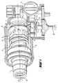
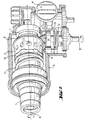
- a tool spindle 1 that can be rotated at least partially about an axis of rotation A. for fastening a tool holder, not shown, of a part shown only combined electric hand tool device with several operating modes an outer Sleeve 2 coaxially assigned non-rotatably, which several, distributed over the circumference, radial Has openings 3, in which, via a manually operated mode selector switch 4, Transversely to the axis of rotation A and rotatable with a housing 5 of the electric hand tool device connected bolt 6 engages radially.
- the sleeve 2 is around a guide tube 7 with an internal flight piston, not shown, arranged around and on one End face provided with a conical pinion 8, which is at least partially in engagement stands with an associated conical drive pinion 9, the drive shaft B is oriented perpendicular to the axis of rotation A.
- the sleeve is one with respect to its other end face Coupled clutch plate 10 adjacent, which with the guide tube 7 positively rotatably connected and axially pressed against the sleeve 2 via a compression spring 11.
- the Bolt 6 which can be displaced perpendicularly to the axis of rotation A, has a pin 6 on the shaft of the drive pinion 9 arranged sliding sleeve 12 connected, which form-fitting via a Sliding sleeve 12 engaging switching plate 13 with the manually operated mode selector switch 4 is connected.
Landscapes
- Engineering & Computer Science (AREA)
- Mechanical Engineering (AREA)
- Percussive Tools And Related Accessories (AREA)
- Drilling And Boring (AREA)
Abstract
Description
Claims (6)
- Elektrohandwerkzeuggerät mit mehreren Betriebsmodi und einer zumindest teilweise um eine Drehachse (A) drehbaren Werkzeugspindel (1), der eine äussere Hülse (2) koaxial drehfest zugeordnet ist, welche zumindest eine radiale Öffnung (3) aufweist, in welche ein über einen manuell betätigbaren Modenwahlschalter (4) quer zur Drehachse (A) versetzbarer und drehfest mit einem Gehäuse (5) des Elektrohandwerkzeuggerätes verbundener Bolzen (6) in zumindest einem Betriebsmode radial eingreift, dadurch gekennzeichnet, dass der Bolzen (6) mit einer auf einer Antriebswelle (B) angeordneten Schiebehülse (12) verbunden ist.
- Elektrohandwerkzeuggerät nach Anspruch 1, dadurch gekennzeichnet, dass mehrere radiale Öffnungen (3) über dem Umfang der Hülse (2) verteilt sind.
- Elektrohandwerkzeuggerät nach Anspruch 1 oder Anspruch 2, dadurch gekennzeichnet, dass an der Hülse (2) ein kegelförmigen Ritzel (8) ausgebildet ist, welches zumindest teilweise im Eingriff mit einem zugeordneten kegelförmigen Antriebsritzel (9) der Antriebswelle (B) angeordnet ist.
- Elektrohandwerkzeuggerät nach einem der vorherigen Ansprüche, dadurch gekennzeichnet, dass die Schiebehülse (12) über ein formschlüssig eingreifendes Schaltblech (13) mit dem manuell betätigbaren Modenwahlschalter (4) verbunden ist.
- Elektrohandwerkzeuggerät nach einem der vorherigen Ansprüche, dadurch gekennzeichnet, dass die Hülse (2) um ein Führungsrohr (7) mit einem innenliegenden Flugkolben herum angeordnet ist.
- Elektrohandwerkzeuggerät nach Anspruch 5, dadurch gekennzeichnet, dass die Hülse (2) benachbart einer Kupplungsscheibe (10) zugeordnet ist, welche mit dem Führungsrohr (7) formschlüssig drehfest verbunden und über eine Druckfeder (11) axial gegen die Hülse (2) druckvorgespannt ist.
Applications Claiming Priority (2)
| Application Number | Priority Date | Filing Date | Title |
|---|---|---|---|
| DE10033100 | 2000-07-07 | ||
| DE10033100A DE10033100A1 (de) | 2000-07-07 | 2000-07-07 | Kombiniertes Elektrohandwerkzeuggerät |
Publications (2)
| Publication Number | Publication Date |
|---|---|
| EP1170096A1 true EP1170096A1 (de) | 2002-01-09 |
| EP1170096B1 EP1170096B1 (de) | 2004-06-02 |
Family
ID=7648156
Family Applications (1)
| Application Number | Title | Priority Date | Filing Date |
|---|---|---|---|
| EP01810622A Expired - Lifetime EP1170096B1 (de) | 2000-07-07 | 2001-06-26 | Kombiniertes Elektrohandwerkzeuggerät |
Country Status (5)
| Country | Link |
|---|---|
| US (1) | US6510903B2 (de) |
| EP (1) | EP1170096B1 (de) |
| JP (1) | JP4772226B2 (de) |
| CN (1) | CN1207131C (de) |
| DE (2) | DE10033100A1 (de) |
Families Citing this family (32)
| Publication number | Priority date | Publication date | Assignee | Title |
|---|---|---|---|---|
| GB0008465D0 (en) | 2000-04-07 | 2000-05-24 | Black & Decker Inc | Rotary hammer mode change mechanism |
| DE10111746A1 (de) * | 2001-03-12 | 2002-09-19 | Hilti Ag | Schaltübertragungsmittel zur kombinierten Schaltung eines Getriebes |
| DE10225239A1 (de) * | 2002-06-06 | 2003-12-18 | Hilti Ag | Modiwahlschalter für kombinierte Elektrohandwerkzeugmaschine |
| GB0214772D0 (en) * | 2002-06-26 | 2002-08-07 | Black & Decker Inc | Hammer |
| GB2394516A (en) | 2002-10-23 | 2004-04-28 | Black & Decker Inc | Power tool |
| GB0311045D0 (en) * | 2003-05-14 | 2003-06-18 | Black & Decker Inc | Rotary hammer |
| FR2863518B1 (fr) * | 2003-12-15 | 2006-01-13 | Montabert Roger | Dispositif d'assemblage du carter et du corps d'un brise roche hydraulique |
| DE102004018084B3 (de) * | 2004-04-08 | 2005-11-17 | Hilti Ag | Hammerbohrgerät |
| DE102004025951A1 (de) * | 2004-05-27 | 2005-12-22 | Robert Bosch Gmbh | Handwerkzeugmaschine, insbesondere Bohr- und/oder Schlaghammer |
| DE102004034268B3 (de) * | 2004-07-15 | 2005-12-29 | Wacker Construction Equipment Ag | Bohrhammer mit Sicherheitskupplung |
| JP4515181B2 (ja) * | 2004-07-20 | 2010-07-28 | 株式会社マキタ | 電動ハンマドリル |
| DE102004052329A1 (de) * | 2004-10-27 | 2006-05-04 | Kress-Elektrik Gmbh & Co. Elektromotorenfabrik | Synchronisations- und Schalteinheit für Einknopf-Wahlschalter sowie Elektrowerkzeug mit Synchronisations- und Schalteinheit |
| EP1674743B1 (de) * | 2004-12-23 | 2014-01-22 | Black & Decker Inc. | Antriebsmechanismus für ein Kraftwerkzeug |
| EP1674207B1 (de) * | 2004-12-23 | 2008-12-10 | BLACK & DECKER INC. | Kraftwerkzeug |
| GB2428880A (en) * | 2005-07-27 | 2007-02-07 | Unity Opto Technology Co Ltd | White Light LED |
| US7469752B2 (en) * | 2005-12-02 | 2008-12-30 | Makita Corporation | Power tool |
| DE102007009986A1 (de) * | 2007-03-02 | 2008-09-04 | Robert Bosch Gmbh | Handwerkzeugmaschine |
| JP4981506B2 (ja) * | 2007-04-12 | 2012-07-25 | 株式会社マキタ | ハンマードリル |
| US7806198B2 (en) | 2007-06-15 | 2010-10-05 | Black & Decker Inc. | Hybrid impact tool |
| US9193053B2 (en) | 2008-09-25 | 2015-11-24 | Black & Decker Inc. | Hybrid impact tool |
| US8631880B2 (en) | 2009-04-30 | 2014-01-21 | Black & Decker Inc. | Power tool with impact mechanism |
| US8460153B2 (en) | 2009-12-23 | 2013-06-11 | Black & Decker Inc. | Hybrid impact tool with two-speed transmission |
| US8584770B2 (en) | 2010-03-23 | 2013-11-19 | Black & Decker Inc. | Spindle bearing arrangement for a power tool |
| DE102010041259A1 (de) * | 2010-09-23 | 2012-03-29 | Robert Bosch Gmbh | Handwerkzeugmaschinenschaltvorrichtung |
| WO2012170092A2 (en) * | 2011-03-11 | 2012-12-13 | Winnard Stanley D | Handheld drive device |
| CN102794751B (zh) * | 2011-05-23 | 2017-02-01 | 博世电动工具(中国)有限公司 | 电动工具及其传动转换机构 |
| US9630307B2 (en) * | 2012-08-22 | 2017-04-25 | Milwaukee Electric Tool Corporation | Rotary hammer |
| GB201321893D0 (en) | 2013-12-11 | 2014-01-22 | Black & Decker Inc | Rotary Hammer |
| US10399214B2 (en) | 2014-12-17 | 2019-09-03 | Stanley D. Winnard | Ratchet wrench |
| CN108838933B (zh) * | 2018-09-20 | 2020-06-16 | 上海虎啸电动工具有限公司 | 一种便捷型电动套筒螺丝刀 |
| CN110181082B (zh) * | 2019-06-27 | 2024-11-01 | 上饶风茂工业电气中心(个人独资) | 摇臂钻床电器四位组合开关 |
| JP7696237B2 (ja) * | 2021-06-10 | 2025-06-20 | 株式会社マキタ | 回転打撃工具 |
Citations (4)
| Publication number | Priority date | Publication date | Assignee | Title |
|---|---|---|---|---|
| US3828865A (en) * | 1969-07-30 | 1974-08-13 | Metabowerke Kg | Hammer drill |
| US4763733A (en) * | 1985-10-26 | 1988-08-16 | Hilti Aktiengesellschaft | Hammer drill with rotational lock |
| US5456324A (en) * | 1993-11-26 | 1995-10-10 | Hitachi Koki Company Limited | Percussion hammer |
| EP0759342A2 (de) * | 1995-08-18 | 1997-02-26 | Makita Corporation | Bohrhammer mit einem Betriebsart-Umschaltmechanismus |
Family Cites Families (6)
| Publication number | Priority date | Publication date | Assignee | Title |
|---|---|---|---|---|
| ZA803409B (en) * | 1979-06-18 | 1981-05-27 | Kango Electric Hammers Ltd | Hammer drill |
| DE3422195C2 (de) * | 1984-06-15 | 1987-04-09 | Günter Horst 7927 Sontheim Röhm | Schlagbohreinrichtung |
| JPH1094977A (ja) * | 1996-09-20 | 1998-04-14 | Hitachi Koki Co Ltd | 打撃工具の動作モード切換え装置 |
| JP2000033507A (ja) * | 1998-07-16 | 2000-02-02 | Ryobi Ltd | ハンマードリルの打撃力調整機構 |
| US6223833B1 (en) * | 1999-06-03 | 2001-05-01 | One World Technologies, Inc. | Spindle lock and chipping mechanism for hammer drill |
| JP3688943B2 (ja) * | 1999-08-26 | 2005-08-31 | 株式会社マキタ | ハンマードリル |
-
2000
- 2000-07-07 DE DE10033100A patent/DE10033100A1/de not_active Withdrawn
-
2001
- 2001-06-26 DE DE50102458T patent/DE50102458D1/de not_active Expired - Lifetime
- 2001-06-26 EP EP01810622A patent/EP1170096B1/de not_active Expired - Lifetime
- 2001-06-28 CN CNB011218231A patent/CN1207131C/zh not_active Expired - Fee Related
- 2001-07-05 US US09/899,446 patent/US6510903B2/en not_active Expired - Lifetime
- 2001-07-09 JP JP2001208010A patent/JP4772226B2/ja not_active Expired - Fee Related
Patent Citations (4)
| Publication number | Priority date | Publication date | Assignee | Title |
|---|---|---|---|---|
| US3828865A (en) * | 1969-07-30 | 1974-08-13 | Metabowerke Kg | Hammer drill |
| US4763733A (en) * | 1985-10-26 | 1988-08-16 | Hilti Aktiengesellschaft | Hammer drill with rotational lock |
| US5456324A (en) * | 1993-11-26 | 1995-10-10 | Hitachi Koki Company Limited | Percussion hammer |
| EP0759342A2 (de) * | 1995-08-18 | 1997-02-26 | Makita Corporation | Bohrhammer mit einem Betriebsart-Umschaltmechanismus |
Also Published As
| Publication number | Publication date |
|---|---|
| US6510903B2 (en) | 2003-01-28 |
| DE50102458D1 (de) | 2004-07-08 |
| EP1170096B1 (de) | 2004-06-02 |
| JP4772226B2 (ja) | 2011-09-14 |
| US20020003044A1 (en) | 2002-01-10 |
| JP2002059375A (ja) | 2002-02-26 |
| CN1332067A (zh) | 2002-01-23 |
| CN1207131C (zh) | 2005-06-22 |
| DE10033100A1 (de) | 2002-01-17 |
Similar Documents
| Publication | Publication Date | Title |
|---|---|---|
| EP1170096B1 (de) | Kombiniertes Elektrohandwerkzeuggerät | |
| EP0221009B1 (de) | Bohrhammer mit Dreharretierung | |
| DE10205030A1 (de) | Betriebsmodi-Schalteinheit einer Handwerkzeugmaschine | |
| EP1944132B1 (de) | Handgeführter Bohrhammer | |
| EP2038090A1 (de) | Elektrohandwerkzeug | |
| DE2144449A1 (de) | Hammerbohrmaschine | |
| EP0463416B1 (de) | Elektrische Schlagbohrmaschine | |
| CH695369A5 (de) | Schaltwerk für ein kombiniertes Handwerkzeuggerät. | |
| DE2165066A1 (de) | Schlagbohrmaschine | |
| EP3461594B1 (de) | Getriebeanordnung für eine angetriebene werkzeugmaschine | |
| EP0211801A1 (de) | Bohrgerät | |
| EP0040261A1 (de) | Elektrowerkzeug mit einem Zweiganggetriebe | |
| DE10205124C1 (de) | Gewinnungsvorrichtung | |
| DE4205840C2 (de) | Bohrhammer mit Meißelfunktion | |
| DE2951420C2 (de) | Schlagbohrmaschine | |
| EP2104594B1 (de) | Handwerkzeugmaschine | |
| DE102004042734A1 (de) | Schaltvorrichtung mit einer Synchronisationsfeder | |
| EP2314419B1 (de) | Motorisch angetriebenes Werkzeuggerät | |
| EP4017685A1 (de) | Handwerkzeugmaschine | |
| EP0489687B1 (de) | Bohr- und Meisselgerät | |
| EP2632642A1 (de) | Handwerkzeugmaschine mit einem mechanischen schlagwerk | |
| DE3322963A1 (de) | Bohrhammer | |
| DE102004056411A1 (de) | Handwerkzeugmaschine mit Betriebsartumschaltung | |
| DE102006020925B4 (de) | Bohrwerkzeuggerät, insbesondere Bohrhammer | |
| DE1541192C (de) | Zahnärztliches Turbmenhandstuck |
Legal Events
| Date | Code | Title | Description |
|---|---|---|---|
| PUAI | Public reference made under article 153(3) epc to a published international application that has entered the european phase |
Free format text: ORIGINAL CODE: 0009012 |
|
| AK | Designated contracting states |
Kind code of ref document: A1 Designated state(s): AT BE CH CY DE DK ES FI FR GB GR IE IT LI LU MC NL PT SE TR Kind code of ref document: A1 Designated state(s): CH DE FR GB LI NL SE |
|
| AX | Request for extension of the european patent |
Free format text: AL;LT;LV;MK;RO;SI |
|
| 17P | Request for examination filed |
Effective date: 20020709 |
|
| AKX | Designation fees paid |
Free format text: CH DE FR GB LI NL SE |
|
| GRAP | Despatch of communication of intention to grant a patent |
Free format text: ORIGINAL CODE: EPIDOSNIGR1 |
|
| GRAS | Grant fee paid |
Free format text: ORIGINAL CODE: EPIDOSNIGR3 |
|
| GRAA | (expected) grant |
Free format text: ORIGINAL CODE: 0009210 |
|
| AK | Designated contracting states |
Kind code of ref document: B1 Designated state(s): CH DE FR GB LI NL SE |
|
| REG | Reference to a national code |
Ref country code: GB Ref legal event code: FG4D Free format text: NOT ENGLISH |
|
| REG | Reference to a national code |
Ref country code: SE Ref legal event code: TRGR |
|
| REG | Reference to a national code |
Ref country code: CH Ref legal event code: EP |
|
| REF | Corresponds to: |
Ref document number: 50102458 Country of ref document: DE Date of ref document: 20040708 Kind code of ref document: P |
|
| REG | Reference to a national code |
Ref country code: IE Ref legal event code: FG4D Free format text: GERMAN |
|
| GBT | Gb: translation of ep patent filed (gb section 77(6)(a)/1977) |
Effective date: 20040825 |
|
| REG | Reference to a national code |
Ref country code: IE Ref legal event code: FD4D |
|
| ET | Fr: translation filed | ||
| PLBE | No opposition filed within time limit |
Free format text: ORIGINAL CODE: 0009261 |
|
| STAA | Information on the status of an ep patent application or granted ep patent |
Free format text: STATUS: NO OPPOSITION FILED WITHIN TIME LIMIT |
|
| 26N | No opposition filed |
Effective date: 20050303 |
|
| PG25 | Lapsed in a contracting state [announced via postgrant information from national office to epo] |
Ref country code: NL Free format text: LAPSE BECAUSE OF NON-PAYMENT OF DUE FEES Effective date: 20060101 |
|
| NLV4 | Nl: lapsed or anulled due to non-payment of the annual fee |
Effective date: 20060101 |
|
| REG | Reference to a national code |
Ref country code: FR Ref legal event code: PLFP Year of fee payment: 16 |
|
| REG | Reference to a national code |
Ref country code: FR Ref legal event code: PLFP Year of fee payment: 17 |
|
| REG | Reference to a national code |
Ref country code: FR Ref legal event code: PLFP Year of fee payment: 18 |
|
| PGFP | Annual fee paid to national office [announced via postgrant information from national office to epo] |
Ref country code: CH Payment date: 20180621 Year of fee payment: 18 Ref country code: DE Payment date: 20180625 Year of fee payment: 18 |
|
| PGFP | Annual fee paid to national office [announced via postgrant information from national office to epo] |
Ref country code: FR Payment date: 20180620 Year of fee payment: 18 |
|
| PGFP | Annual fee paid to national office [announced via postgrant information from national office to epo] |
Ref country code: SE Payment date: 20180620 Year of fee payment: 18 |
|
| PGFP | Annual fee paid to national office [announced via postgrant information from national office to epo] |
Ref country code: GB Payment date: 20180620 Year of fee payment: 18 |
|
| REG | Reference to a national code |
Ref country code: DE Ref legal event code: R119 Ref document number: 50102458 Country of ref document: DE |
|
| REG | Reference to a national code |
Ref country code: SE Ref legal event code: EUG |
|
| PG25 | Lapsed in a contracting state [announced via postgrant information from national office to epo] |
Ref country code: SE Free format text: LAPSE BECAUSE OF NON-PAYMENT OF DUE FEES Effective date: 20190627 |
|
| REG | Reference to a national code |
Ref country code: CH Ref legal event code: PL |
|
| GBPC | Gb: european patent ceased through non-payment of renewal fee |
Effective date: 20190626 |
|
| PG25 | Lapsed in a contracting state [announced via postgrant information from national office to epo] |
Ref country code: DE Free format text: LAPSE BECAUSE OF NON-PAYMENT OF DUE FEES Effective date: 20200101 Ref country code: GB Free format text: LAPSE BECAUSE OF NON-PAYMENT OF DUE FEES Effective date: 20190626 |
|
| PG25 | Lapsed in a contracting state [announced via postgrant information from national office to epo] |
Ref country code: CH Free format text: LAPSE BECAUSE OF NON-PAYMENT OF DUE FEES Effective date: 20190630 Ref country code: LI Free format text: LAPSE BECAUSE OF NON-PAYMENT OF DUE FEES Effective date: 20190630 |
|
| PG25 | Lapsed in a contracting state [announced via postgrant information from national office to epo] |
Ref country code: FR Free format text: LAPSE BECAUSE OF NON-PAYMENT OF DUE FEES Effective date: 20190630 |