EP1169192B1 - Verstellvorrichtung - Google Patents
Verstellvorrichtung Download PDFInfo
- Publication number
- EP1169192B1 EP1169192B1 EP01909480A EP01909480A EP1169192B1 EP 1169192 B1 EP1169192 B1 EP 1169192B1 EP 01909480 A EP01909480 A EP 01909480A EP 01909480 A EP01909480 A EP 01909480A EP 1169192 B1 EP1169192 B1 EP 1169192B1
- Authority
- EP
- European Patent Office
- Prior art keywords
- shaft
- gear
- seat
- motor
- rail
- Prior art date
- Legal status (The legal status is an assumption and is not a legal conclusion. Google has not performed a legal analysis and makes no representation as to the accuracy of the status listed.)
- Expired - Lifetime
Links
Images



Classifications
-
- B—PERFORMING OPERATIONS; TRANSPORTING
- B60—VEHICLES IN GENERAL
- B60N—SEATS SPECIALLY ADAPTED FOR VEHICLES; VEHICLE PASSENGER ACCOMMODATION NOT OTHERWISE PROVIDED FOR
- B60N2/00—Seats specially adapted for vehicles; Arrangement or mounting of seats in vehicles
- B60N2/02—Seats specially adapted for vehicles; Arrangement or mounting of seats in vehicles the seat or part thereof being movable, e.g. adjustable
- B60N2/04—Seats specially adapted for vehicles; Arrangement or mounting of seats in vehicles the seat or part thereof being movable, e.g. adjustable the whole seat being movable
- B60N2/06—Seats specially adapted for vehicles; Arrangement or mounting of seats in vehicles the seat or part thereof being movable, e.g. adjustable the whole seat being movable slidable
- B60N2/067—Seats specially adapted for vehicles; Arrangement or mounting of seats in vehicles the seat or part thereof being movable, e.g. adjustable the whole seat being movable slidable by linear actuators, e.g. linear screw mechanisms
-
- B—PERFORMING OPERATIONS; TRANSPORTING
- B60—VEHICLES IN GENERAL
- B60N—SEATS SPECIALLY ADAPTED FOR VEHICLES; VEHICLE PASSENGER ACCOMMODATION NOT OTHERWISE PROVIDED FOR
- B60N2/00—Seats specially adapted for vehicles; Arrangement or mounting of seats in vehicles
- B60N2/02—Seats specially adapted for vehicles; Arrangement or mounting of seats in vehicles the seat or part thereof being movable, e.g. adjustable
- B60N2/0224—Non-manual adjustments, e.g. with electrical operation
- B60N2/02246—Electric motors therefor
- B60N2/02258—Electric motors therefor characterised by the mounting of the electric motor for adjusting the seat
-
- B—PERFORMING OPERATIONS; TRANSPORTING
- B60—VEHICLES IN GENERAL
- B60N—SEATS SPECIALLY ADAPTED FOR VEHICLES; VEHICLE PASSENGER ACCOMMODATION NOT OTHERWISE PROVIDED FOR
- B60N2/00—Seats specially adapted for vehicles; Arrangement or mounting of seats in vehicles
- B60N2/02—Seats specially adapted for vehicles; Arrangement or mounting of seats in vehicles the seat or part thereof being movable, e.g. adjustable
- B60N2/0224—Non-manual adjustments, e.g. with electrical operation
- B60N2/02246—Electric motors therefor
- B60N2/02253—Electric motors therefor characterised by the transmission between the electric motor and the seat or seat parts
Definitions
- the invention relates to an electromotive device for the longitudinal adjustment of seats in motor vehicles.
- Previously known electromotive longitudinal seat adjustments are based on the principle that one or more gear mechanisms are used to secure a seat, particularly one Motor vehicle seat to move with respect to its longitudinal position by means of a motor. This allows the size of the footwell in front of the seat to be changed adaptable to the leg length of people of different sizes.
- US 5,950,978 discloses a seat adjustment device for a motor vehicle. Below A drive motor is arranged in a vehicle seat.
- the vehicle seat has one Upper rail on, which realtively to a lower rail arranged on the floor of the vehicle 4 is movable.
- the drive power of the drive motor is by means of a worm gear transmitted to a transmission wave.
- Another worm gear is formed on the stub shaft, which is provided with a screw running parallel to the lower rail. The The worm threads of the worm mesh with recesses in the lower rail 4.
- the motor is usually located under the seat surface of the seat.
- the seat is arranged on two parallel top rails, which are in respective bottom rails are led.
- the power of the engine is transferred to a transmission shaft.
- the torque of the Transmission shaft is then shifted into synchronous motion via two gear mechanisms the upper rails arranged in the respective parallel lower rails are deflected.
- a frequently used system with spindle gears stands out in particular characterized by high crash resistance.
- the disadvantage is the fast rotating transmission shaft, which causes an unfavorable, high noise level. Beyond that runs the transmission shaft in the immediate vicinity of the front edge of the seat and therefore in the vicinity of the foot area. This allows them to easily pass through the on the Person in the seat or damaged by an object in the footwell will or disrupt them.
- the object of the present invention is a device for longitudinal adjustment to create seats in motor vehicles, one against damage more protected construction and a reduced noise level during operation having.
- the implementation of the invention can be done by simple modifications to a Proven and proven seat adjustment can be achieved, with the majority the reliable and advantageous parts of the device used so far can be taken over. This can keep costs down and are essentially limited to the realization and testing of the new features according to the invention.
- a synchronous motorized drive of two under the is also advantageous Upper rails arranged in parallel in respective lower rails via a seat Transmission wave in combination with the features of the present invention.
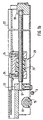
- a motor 1 can be seen in FIG. 1 a, the shaft of which extends along the axis 2 and is designed as a toothed rack (not shown).
- the rack is in mesh with a plastic gear 4 mounted on a profile shaft 3.
- the gear wheels 4, 6 are located in corresponding housings 7, 8, which serve the gears 4, 6 as bearings at the same time.
- the housing 7 is firmly connected to the motor 1, or is in one piece with a housing for the shaft of the motor 1 is formed while the housing 8 is attached to the seat with one Upper rail 9 is connected.
- the gear attached to the profile shaft 3 6 is in mesh with another gear 10, which on a first shaft 11 is arranged.
- This increases the speed of the first shaft 11 or, in other words, if the same speed of the first shaft 11 is to be achieved in comparison with a device without this gear mechanism 29, the transmission shaft 3 must rotate at a reduced speed.
- the speed of the transmission shaft is thus reduced from 3000 rpm to 1000 rpm in comparison to a device without an additional gear mechanism 29, the torque acting on the first shaft 11 being simultaneously increased by the corresponding reciprocal factor.
- the first wave 11 have a rigidity appropriate to the higher torque.
- the additional gear it is also possible to use a motor 1 with a gear to replace a gearless motor 1.
- the adjustment of a fixed engine speed to a suitable speed for the operation of the device can by the additional gear mechanism 29 take place.
- the first shaft 11 is received in a housing 12 which is fixedly connected to the top rail 9 of a guide rail arrangement 13 and / or the housing 8. Bearings 14 for the first shaft 11 are provided for low-friction rotation.
- the gearwheel 16 is mounted on a second shaft 17, which is mounted parallel to the guide rail arrangement 13 in the upper rail 9 in the receiving position 18.
- the gear mechanism 19 formed by the worm 15 and the gearwheel 16 together with the shafts 11 and 17 is accommodated in a housing 20 which is arranged between guide rails 21 of the upper rail 9 and is firmly connected to the latter.
- the second shaft 17 is designed as a spindle on which a spindle nut 23 fastened to a lower rail 22 is moved axially.
- the spindle nut 23 is fastened to the lower rail 22 with screws 24.
- Gear mechanism 28 instead of that formed by the spindle 17 and the spindle nut 23 Gear mechanism 28 also includes a rack and pinion, or one toothed rack with a corresponding worm is used become.
- the guide rail arrangement 13 consists of a on a vehicle floor (not shown) attached bottom rail 22 and a longitudinally therein displaceable upper rail 9.
- the lower rail 22 has an essentially C-shaped cross section. The side lying on the vehicle floor the lower rail 22 is closed, while the upper side for the passage of the Upper rail 9 is open. On the upper side, the lower rail 22 points inwards bent-back edges 25, which have a downwardly open U-shaped groove form. This serves as a contact strip for the bent back guide rails 21 of the top rail 9.
- rounded in a quarter circle 22 balls 26 are included, the top rail 9 as a support and friction-reducing storage for a longitudinal displacement in the on the vehicle floor attached bottom rail 22 serve.
- the bent back guide rails 21 of the top rail 9 have inclined support surfaces 27, which in Contact the balls 26. About the points of contact between the balls 26 and the bearing surfaces 27 becomes the full weight of the entire seat transferred to the lower rail 22. Because of the outward slant Contact surfaces 27 trained guide rails and through their contact with the bent back edges 25 will be a stable and low-friction guidance of the Upper rail 9 ensured in the lower rail 22.
- the profile shaft 3 shown in FIG. 1a is actually in the present embodiment extended beyond the length shown and with the shown Gear mechanisms 19, 28, 29 arranged in mirror image, further Gear mechanisms, not shown, and a further guide rail arrangement 13 connected.
- the power of the motor 1 can thus be synchronized to two Guide rail assemblies 13 are transferred to two top rails 9 in to drive two bottom rails 22 arranged in parallel.
- the axis 2 of the shaft of the motor 1 is parallel to the direction of displacement the seat arranged.
- An arrangement of the axis of the is also conceivable Motor shaft e.g. perpendicular to the direction of displacement, as shown in Fig. 2.
Landscapes
- Engineering & Computer Science (AREA)
- Aviation & Aerospace Engineering (AREA)
- Transportation (AREA)
- Mechanical Engineering (AREA)
- Seats For Vehicles (AREA)
Description
- Fig. 1a
- die erfindungsgemäße Verstellvorrichtung im Längsschnitt,
- Fig. 1b
- einen Schnitt längs der Linie A - A von Fig. 1a,
- Fig. 1c
- einen Schnitt längs der Linie C - C von Fig. 1a, und
- Fig. 2
- eine weitere Ausführungsform der erfindungsgemäßen Verstellvorrichtung im Längsschnitt.
- 1
- Motor
- 2
- Achse
- 3
- Profilwelle
- 4
- Zahnrad
- 5
- Getriebemechanismus
- 6
- Zahnrad
- 7
- Gehäuse
- 8
- Gehäuse
- 9
- Oberschiene
- 10
- Zahnrad
- 11
- erste Welle
- 12
- Gehäuse
- 13
- Führungsschienenanordnung
- 14
- Lager
- 15
- Schnecke
- 16
- Zahnrad
- 17
- zweite Welle
- 18
- Aufnahmelager
- 19
- Getriebemechanismus
- 20
- Gehäuse
- 21
- Führungsschiene
- 22
- Unterschiene
- 23
- Spindelmutter
- 24
- Schraube
- 25
- zurückgebogene Ränder
- 26
- Kugel
- 27
- Auflagefläche
- 28
- Getriebemechanismus
- 29
- Getriebemechanismus
Claims (6)
- Vorrichtung zur Längsverstellung von Sitzen in Kraftfahrzeugen mit einem Motor (1) und einer an einem Sitz festgelegten Oberschiene (9) und einer an einem Boden festgelegten Unterschiene (22), wobei die Unterschiene (22) und die Oberschiene (9) relativ zueinander verschiebbar angeordnet sind sowie einem ersten Getriebemechanismus (5) zur Übertragung von Motorleistung auf eine Übertragungswelle (3) und ein Untersetzungsgetriebe (29) zur Übertragung der Motorleistung von der Übertragungswelle (3) auf eine erste Welle (11), mittels welchem die Übertragungswelle (3) in ihrer Drehzahl reduzierbar und weiter unter den Sitz verlegbar ist und einem zweiten Getriebemechanismus (19) zur Übertragung der Motorleistung von der ersten Welle (11) auf eine parallel zur Oberschiene (9) angeordnete zweite Welle und einem dritten, durch die zweite Welle (17) angetriebenen Getriebemechanismus (28) zur Verstellung der Position der Oberschiene (9) relativ zur Unterschiene (22), dadurch gekennzeichnet, dass das Untersetzungsgetriebe (29) ein Untersetzungsverhältnis von ≤ 0,3 aufweist.
- Vorrichtung nach Anspruch 1, bei welcher die Übertragungswelle (3) eine Profilwelle ist.
- Vorrichtung nach einem der Ansprüche 1 bis 2, bei welcher an dem Sitz zwei parallele Oberschienen (9) angeordnet sind, die in jeweiligen Unterschienen (22) verschiebbar sind, wobei die Oberschienen (9) mittels der Übertragungswelle und jeweils entsprechenden, die Motorleistung übertragenden Mechanismen (19, 28, 29) synchron verschoben werden.
- Vorrichtung nach einem der Ansprüche 1 bis 3, bei welcher mindestens ein Getriebemechanismus (19, 28) ein Spindelgetriebe ist.
- Vorrichtung nach einem der Ansprüche 1 bis 3, bei welcher mindestens ein Getriebemechanismus (19, 28) ein Schneckengetriebe ist.
- Vorrichtung nach einem der Ansprüche 1 bis 5, bei welcher der Motor (1) unter dem Sitz angeordnet und an diesem befestigt ist.
Applications Claiming Priority (3)
| Application Number | Priority Date | Filing Date | Title |
|---|---|---|---|
| DE10004092 | 2000-01-31 | ||
| DE10004092A DE10004092A1 (de) | 2000-01-31 | 2000-01-31 | Verstellvorrichtung |
| PCT/DE2001/000168 WO2001056828A1 (de) | 2000-01-31 | 2001-01-17 | Verstellvorrichtung |
Publications (2)
| Publication Number | Publication Date |
|---|---|
| EP1169192A1 EP1169192A1 (de) | 2002-01-09 |
| EP1169192B1 true EP1169192B1 (de) | 2004-10-06 |
Family
ID=7629289
Family Applications (1)
| Application Number | Title | Priority Date | Filing Date |
|---|---|---|---|
| EP01909480A Expired - Lifetime EP1169192B1 (de) | 2000-01-31 | 2001-01-17 | Verstellvorrichtung |
Country Status (3)
| Country | Link |
|---|---|
| EP (1) | EP1169192B1 (de) |
| DE (2) | DE10004092A1 (de) |
| WO (1) | WO2001056828A1 (de) |
Cited By (1)
| Publication number | Priority date | Publication date | Assignee | Title |
|---|---|---|---|---|
| DE202004005225U1 (de) * | 2004-04-02 | 2005-08-18 | Brose Fahrzeugteile Gmbh & Co. Kommanditgesellschaft, Coburg | Sitzlehnenverstellung an einem Kraftfahrzeugsitz |
Families Citing this family (4)
| Publication number | Priority date | Publication date | Assignee | Title |
|---|---|---|---|---|
| DE20300765U1 (de) * | 2003-01-14 | 2004-07-22 | Brose Fahrzeugteile Gmbh & Co. Kg, Coburg | Sitzverstelleinrichtung |
| DE202004006273U1 (de) * | 2004-04-21 | 2005-09-01 | Brose Fahrzeugteile Gmbh & Co. Kommanditgesellschaft, Coburg | Verstelleinrichtung an einem Kraftfahrzeugsitz |
| CN110834572B (zh) * | 2019-11-04 | 2024-12-10 | 无锡锡玮科技有限公司 | 一种具有避让位的非对称长距离铝合金电动滑轨 |
| DE102022104330A1 (de) * | 2022-02-23 | 2023-08-24 | Brose Fahrzeugteile SE & Co. Kommanditgesellschaft, Coburg | Fahrzeugsitzbaugruppe mit zwei quer zueinander beabstandbaren Fahrzeugsitzen |
Family Cites Families (5)
| Publication number | Priority date | Publication date | Assignee | Title |
|---|---|---|---|---|
| JPS6430850A (en) * | 1987-07-24 | 1989-02-01 | Aisin Seiki | Driving device for power seat |
| JP3131394B2 (ja) * | 1996-11-12 | 2001-01-31 | 池田物産株式会社 | 自動車用シートのパワースライド装置 |
| JP3242850B2 (ja) * | 1996-11-12 | 2001-12-25 | ジョンソン コントロールズ オートモーティブ システムズ株式会社 | 自動車用シートのパワースライド装置 |
| US5950978A (en) * | 1996-11-12 | 1999-09-14 | Ikeda Bussan Co., Ltd. | Power seat slide device for motor vehicle |
| JPH10138805A (ja) * | 1996-11-12 | 1998-05-26 | Ikeda Bussan Co Ltd | 自動車用シートのパワースライド装置 |
-
2000
- 2000-01-31 DE DE10004092A patent/DE10004092A1/de not_active Ceased
-
2001
- 2001-01-17 DE DE50103946T patent/DE50103946D1/de not_active Expired - Lifetime
- 2001-01-17 EP EP01909480A patent/EP1169192B1/de not_active Expired - Lifetime
- 2001-01-17 WO PCT/DE2001/000168 patent/WO2001056828A1/de not_active Ceased
Cited By (1)
| Publication number | Priority date | Publication date | Assignee | Title |
|---|---|---|---|---|
| DE202004005225U1 (de) * | 2004-04-02 | 2005-08-18 | Brose Fahrzeugteile Gmbh & Co. Kommanditgesellschaft, Coburg | Sitzlehnenverstellung an einem Kraftfahrzeugsitz |
Also Published As
| Publication number | Publication date |
|---|---|
| DE10004092A1 (de) | 2001-08-09 |
| EP1169192A1 (de) | 2002-01-09 |
| DE50103946D1 (de) | 2004-11-11 |
| WO2001056828A1 (de) | 2001-08-09 |
Similar Documents
| Publication | Publication Date | Title |
|---|---|---|
| DE3006331C2 (de) | Getriebe | |
| DE2312395C2 (de) | Vorrichtung zum Auffangen des Axialspiels in einem Schneckengetriebe | |
| DE102005057462B4 (de) | Sitzkomponenten-Verstellvorrichtung und -Verfahren sowie Sitz | |
| DE102012107102A1 (de) | Elektromotorischer Möbelantrieb | |
| DE102016200649A1 (de) | Elektrisch längsverstellbare Lenksäule für ein Kraftfahrzeug | |
| WO2007137670A1 (de) | Türantrieb mit während der türbewegung veränderbarer federvorspannung | |
| DE102014116480B4 (de) | Lagerung einer Schaltnockenwelle | |
| WO2004005761A1 (de) | Anpressvorrichtung | |
| DE10062217B4 (de) | Längseinsteller für einen Fahrzeugsitz | |
| DE69615917T2 (de) | Verstellbares Lager für Sitze | |
| DE4437539C2 (de) | Fahrzeugsitz | |
| WO2000071908A1 (de) | Motor-getriebe-einheit | |
| EP1169192A1 (de) | Verstellvorrichtung | |
| EP1097657A1 (de) | Teleskopantriebseinheit | |
| EP1767389A2 (de) | Schwenkschiebetür für Fahrzeuge, insbesondere Fahrgasttür für Fahrzeuge des öffentlichen Personnenverkehrs | |
| DE102022203224B4 (de) | Getriebeeinheit und Getriebemotor und Verwendung dieser für einen Längseinsteller | |
| DE102020202523A1 (de) | Verstelleinrichtung für einen Fahrzeugsitz | |
| WO2004006723A1 (de) | Elektromotorischer möbelantrieb | |
| DE102005057227B4 (de) | Vorrichtung zur Erzeugung einer Linearbewegung | |
| DE19831442A1 (de) | Getriebe für Sitzverstelleinrichtungen in Kraftfahrzeugen | |
| DE19705589A1 (de) | Vorrichtung zum Bewegen von Teilen eines Kraftfahrzeugs | |
| DE20219932U1 (de) | Getriebe einer Antriebsvorrichtung einer Jalousie o.dgl. | |
| DE102004054860B4 (de) | Walzgerüst zum Walzen von stab- oder rohrförmigen Walzgut | |
| DE102024107399B3 (de) | Antrieb für eine Tür oder ein Fenster mit verbessertem Wirkungsgrad | |
| DE102024100913B3 (de) | Lineares Führungssystem |
Legal Events
| Date | Code | Title | Description |
|---|---|---|---|
| PUAI | Public reference made under article 153(3) epc to a published international application that has entered the european phase |
Free format text: ORIGINAL CODE: 0009012 |
|
| AK | Designated contracting states |
Kind code of ref document: A1 Designated state(s): AT BE CH CY DE DK ES FI FR GB GR IE IT LI LU MC NL PT SE TR |
|
| 17P | Request for examination filed |
Effective date: 20020211 |
|
| 17Q | First examination report despatched |
Effective date: 20020103 |
|
| GRAP | Despatch of communication of intention to grant a patent |
Free format text: ORIGINAL CODE: EPIDOSNIGR1 |
|
| RBV | Designated contracting states (corrected) |
Designated state(s): DE ES FR GB IT |
|
| GRAS | Grant fee paid |
Free format text: ORIGINAL CODE: EPIDOSNIGR3 |
|
| GRAA | (expected) grant |
Free format text: ORIGINAL CODE: 0009210 |
|
| AK | Designated contracting states |
Kind code of ref document: B1 Designated state(s): DE ES FR GB IT |
|
| PG25 | Lapsed in a contracting state [announced via postgrant information from national office to epo] |
Ref country code: IT Free format text: LAPSE BECAUSE OF FAILURE TO SUBMIT A TRANSLATION OF THE DESCRIPTION OR TO PAY THE FEE WITHIN THE PRESCRIBED TIME-LIMIT;WARNING: LAPSES OF ITALIAN PATENTS WITH EFFECTIVE DATE BEFORE 2007 MAY HAVE OCCURRED AT ANY TIME BEFORE 2007. THE CORRECT EFFECTIVE DATE MAY BE DIFFERENT FROM THE ONE RECORDED. Effective date: 20041006 Ref country code: GB Free format text: LAPSE BECAUSE OF FAILURE TO SUBMIT A TRANSLATION OF THE DESCRIPTION OR TO PAY THE FEE WITHIN THE PRESCRIBED TIME-LIMIT Effective date: 20041006 |
|
| REG | Reference to a national code |
Ref country code: GB Ref legal event code: FG4D Free format text: NOT ENGLISH |
|
| REG | Reference to a national code |
Ref country code: IE Ref legal event code: FG4D Free format text: GERMAN |
|
| REF | Corresponds to: |
Ref document number: 50103946 Country of ref document: DE Date of ref document: 20041111 Kind code of ref document: P |
|
| PG25 | Lapsed in a contracting state [announced via postgrant information from national office to epo] |
Ref country code: ES Free format text: LAPSE BECAUSE OF FAILURE TO SUBMIT A TRANSLATION OF THE DESCRIPTION OR TO PAY THE FEE WITHIN THE PRESCRIBED TIME-LIMIT Effective date: 20050117 |
|
| GBV | Gb: ep patent (uk) treated as always having been void in accordance with gb section 77(7)/1977 [no translation filed] |
Effective date: 20041006 |
|
| REG | Reference to a national code |
Ref country code: IE Ref legal event code: FD4D |
|
| PLBE | No opposition filed within time limit |
Free format text: ORIGINAL CODE: 0009261 |
|
| STAA | Information on the status of an ep patent application or granted ep patent |
Free format text: STATUS: NO OPPOSITION FILED WITHIN TIME LIMIT |
|
| ET | Fr: translation filed | ||
| 26N | No opposition filed |
Effective date: 20050707 |
|
| PGFP | Annual fee paid to national office [announced via postgrant information from national office to epo] |
Ref country code: FR Payment date: 20100209 Year of fee payment: 10 |
|
| REG | Reference to a national code |
Ref country code: FR Ref legal event code: ST Effective date: 20110930 |
|
| PG25 | Lapsed in a contracting state [announced via postgrant information from national office to epo] |
Ref country code: FR Free format text: LAPSE BECAUSE OF NON-PAYMENT OF DUE FEES Effective date: 20110131 |
|
| PGFP | Annual fee paid to national office [announced via postgrant information from national office to epo] |
Ref country code: DE Payment date: 20150324 Year of fee payment: 15 |
|
| REG | Reference to a national code |
Ref country code: DE Ref legal event code: R119 Ref document number: 50103946 Country of ref document: DE |
|
| PG25 | Lapsed in a contracting state [announced via postgrant information from national office to epo] |
Ref country code: DE Free format text: LAPSE BECAUSE OF NON-PAYMENT OF DUE FEES Effective date: 20160802 |