EP1167548B1 - Verfahren und Vorrichtung zum Bestimmen der Abkühlwirkung einer strömenden Gasatmosphäre auf Werkstücke - Google Patents
Verfahren und Vorrichtung zum Bestimmen der Abkühlwirkung einer strömenden Gasatmosphäre auf Werkstücke Download PDFInfo
- Publication number
- EP1167548B1 EP1167548B1 EP01110912A EP01110912A EP1167548B1 EP 1167548 B1 EP1167548 B1 EP 1167548B1 EP 01110912 A EP01110912 A EP 01110912A EP 01110912 A EP01110912 A EP 01110912A EP 1167548 B1 EP1167548 B1 EP 1167548B1
- Authority
- EP
- European Patent Office
- Prior art keywords
- measuring body
- workpieces
- temperature
- gas
- quenching
- Prior art date
- Legal status (The legal status is an assumption and is not a legal conclusion. Google has not performed a legal analysis and makes no representation as to the accuracy of the status listed.)
- Expired - Lifetime
Links
Images


Classifications
-
- C—CHEMISTRY; METALLURGY
- C21—METALLURGY OF IRON
- C21D—MODIFYING THE PHYSICAL STRUCTURE OF FERROUS METALS; GENERAL DEVICES FOR HEAT TREATMENT OF FERROUS OR NON-FERROUS METALS OR ALLOYS; MAKING METAL MALLEABLE, e.g. BY DECARBURISATION OR TEMPERING
- C21D1/00—General methods or devices for heat treatment, e.g. annealing, hardening, quenching or tempering
- C21D1/55—Hardenability tests, e.g. end-quench tests
-
- C—CHEMISTRY; METALLURGY
- C21—METALLURGY OF IRON
- C21D—MODIFYING THE PHYSICAL STRUCTURE OF FERROUS METALS; GENERAL DEVICES FOR HEAT TREATMENT OF FERROUS OR NON-FERROUS METALS OR ALLOYS; MAKING METAL MALLEABLE, e.g. BY DECARBURISATION OR TEMPERING
- C21D1/00—General methods or devices for heat treatment, e.g. annealing, hardening, quenching or tempering
- C21D1/56—General methods or devices for heat treatment, e.g. annealing, hardening, quenching or tempering characterised by the quenching agents
- C21D1/613—Gases; Liquefied or solidified normally gaseous material
Definitions
- the invention relates to a method and a device for determining the cooling effect of a flowing gas atmosphere on workpieces according to the preambles of claims 1 and 10.
- the quench chamber is for pressures up to 5.0 MPa and possibly also designed over it, and as Quenching gases may preferably be hydrogen, helium, nitrogen or mixtures of at least two of these gases. These gases are by an unillustrated circulating through the batch (s) passed and sucked off again. On their way the Quenching gases passed through heat exchangers, not shown here and cooled down again.
- the required drive power for the gas circulation increases with the Pressure, but decreases with the atomic weight of the quenching gases, so that the Hydrogen and helium gases or mixtures thereof are preferred give, especially since the heat transfer to these gases especially is favorable and the quenching rate is increased. in this connection Not only the heat transfer on the workpieces, but also plays on the heat exchangers a role.
- thermocouples In such Abschreck compiler one has so far proceeded that one Has provided parts of a stationary batch with thermocouples. Provided this was not possible, one has the batch so-called passive a-probes enclosed, i. special samples with thermocouples without Heating device by heat transfer from the neighboring Workpieces are heated. From the measurement results you have it closed on the deterrence of the workpieces or components (Special edition “Ipsen Report” of the company Ipsen by B. Edenhofer "Control the high-pressure gas quenching by means of heat flow sensor "from October 1995). In this case, measured values of already driven batches as Default used for new batches.
- JP 4-59921 A a laboratory device is known, with which it is possible is the cooling effect of a constant temperature controlled coolant, a solution by determining that a test body, which is provided with a temperature sensor, in one of the cooling liquid heats up distant heater and then by means of a Drive is immersed out of the heater into the coolant and records the temperature changes.
- a test body which is provided with a temperature sensor
- in one of the cooling liquid heats up distant heater and then by means of a Drive is immersed out of the heater into the coolant and records the temperature changes.
- a solution by determining that a test body, which is provided with a temperature sensor, in one of the cooling liquid heats up distant heater and then by means of a Drive is immersed out of the heater into the coolant and records the temperature changes.
- a test body which is provided with a temperature sensor, in one of the cooling liquid heats up distant heater and then by means of a Drive is immersed out of the heater into the coolant and records the temperature changes.
- the invention is therefore based on the object, a method and a Specify device, with which the cooling effect or the quenching effect and the temporal temperature profile, even for large batches continuously and can be determined directly so that any regulatory intervention extremely short term, i. be performed in fractions of a second can. This is to ensure that all workpieces of a batch cooled in accordance with the hardness requirements at high speed metered or quenched and possibly cured.
- the respective heat transfer from the workpieces or the batch of workpieces to the cooling gas affected be harmful to thermal stresses and / or uneven
- the respective Heat transfer are influenced by the cooling gas to the heat exchanger, because the processes on the workpiece surfaces and on the surfaces of the heat exchanger in turn influence each other.
- the task is in full Scope solved, and in particular the cooling effect or the Quenching effect and the temporal temperature course even at large Batches continuously and directly determined, so that any regulatory intervention extremely short term, i. performed in fractions of a second can be.
- This ensures that all workpieces of a batch cooled in accordance with the hardness requirements at high speed metered or quenched and optionally cured.
- the respective heat transfer from the workpieces or the batch of workpieces to the cooling gas tax or controllable, and harmful distortions due to thermal stresses and / or uneven product properties are avoided, and will continue to be the respective heat transfer from the cooling gas to the heat exchanger controllable or controllable because the operations on the workpiece surfaces and on the surfaces of the heat exchanger turn each other influence. It is, so to speak, a synergistic one Effect.
- the use of the invention becomes more important, the more difficult the Workpieces are curable, so for example for low alloyed and difficult to harden workpieces and workpieces with greater mass and complicated room forms, different wall thicknesses etc.
- the invention also relates to the application of the method Claim 1 and the device according to claim 10 for the high pressure gas quenching of workpieces in a quenching chamber with a Heat exchangers at gas pressures between 0.5 and 5.0 MPa, preferably between 1.0 and 4.0 MPa.
- the measuring body 5 is preferably made of an austenitic alloy with a low emission coefficient to heat losses during of heating up and should, in terms of its geometry, Mass and thermal conductivity as far as possible the workpieces correspond to their thermal analysis. However, this is not a requirement, since conversion factors are based on empirical values can be determined. In the simplest case, a cylindrical is sufficient Measuring body 5 with a diameter between 5 and 50 mm, preferably between 15 and 30 mm.
- the measuring body 5 is held in a fixed position by a carrier 8 and concentric surrounded by a heater 9, which is called water-cooled Induction coil is formed whose coolant flow through the arrows 10 and 11 is indicated.
- the induction coil is powered by a medium frequency generator 12 supplied with heating energy, so that it is possible, the To carry out heating very quickly and thoroughly and the Start heating process via a control line 13 and practical to break off inertially.
- the induction coil concentrates its heating performance exclusively on the measuring body 5 and heats the environment, e.g. Chamber walls, not on.
- thermocouple 14 In the vicinity of the sensor unit, a further thermocouple 14 is arranged, with which the gas temperature can be measured.
- the measured values the temperature sensor 6, 7 and 14 are unspecified Test leads a central unit 15 is supplied, in addition to a variety from memory locations not shown, an input keyboard 16 for setpoints and control commands and a display 17 for the display of the measured values or has a sequence of measured values and possibly setpoints. via a data line 18, a printer 19 may be connected.
- the gas flow is indicated by arrows 21.
- the function is as follows:
- the sensor unit 4 allows the direct Measurement of the cooling rate. Just before putting one Batch of workpieces from a heating chamber or a heating furnace in the actual quenching chamber 1, the measuring body 5 to a predetermined Temperature, for example, the austenitizing temperature of the workpieces, heated and then turned off the heating power. After the batch has been converted to the quenching chamber, it is in this as short as possible a predefinable pressure from a quenching gas built and this with appropriate speed in the chamber 1 circulated. The quenching gas cools both the - not here shown - charge and the measuring body 5.
- thermocouples 6 located in the measuring body 5 (edge zone) and 7 (middle) track the local temperatures of the measuring body and allow the Determination of quenching curves, as shown in FIG. to Documentation of these curves will be batch dependent in the Central unit 15 is stored and / or printed out via the printer 19.
- a characteristic Cooling parameters such as a lambda value for the cooling time between 800 and 500 ° C are stored. In this way can be perform a continuous process control, by the example also early deterioration of Abschreckeigenschaften it can be seen how they z. B. by deposits in the heat exchanger can occur.
- the measured with the sensor unit 4 actual Abschreckkurven by means of stored in the central unit 15 target Abschreckkurven Comparison be performed.
- the quenching speeds can be adapted accordingly and regulated, for example by regulating the gas pressure and the gas velocities, thereby minimizing a any distortion of the workpieces can be achieved.
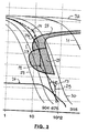
- a representation according to Figure 2 with a logarithmic scale of the abscissa has long been common in metallurgy. From the starting point (0.1 sec) off it is up to the first abscissa line 10 seconds to 2. Absoliss line 100 seconds, so almost 2 minutes, and until the third Abszissenstrich 1000 seconds, so almost 17 minutes etc.
- FIG. 2 shows a so-called Z-T-U diagram (time-temperature conversion), at on the abscissa in logarithmic scale the time in Seconds and on the ordinate in a linear scale the temperature applied are.
- the bold curve represents the following quenching conditions: Pressure: 2.0 MPa, temperature: 50 ° C at a medium gas velocity of 20 m / sec.
- FIG. 3 now shows an enlarged detail from FIG. 2 with the following Additions in a greatly simplified and exaggerated form: at point P1 the actual Abschreckkurve 29a (dashed) now represents the inventive Sensor unit by comparison with a stored setpoint curve according to the curve 29 that the quenching speed is too low.
- the actual Abschreckkurve 29a (dashed) now represents the inventive Sensor unit by comparison with a stored setpoint curve according to the curve 29 that the quenching speed is too low.
Landscapes
- Chemical & Material Sciences (AREA)
- Engineering & Computer Science (AREA)
- Materials Engineering (AREA)
- Thermal Sciences (AREA)
- Crystallography & Structural Chemistry (AREA)
- Mechanical Engineering (AREA)
- Physics & Mathematics (AREA)
- Metallurgy (AREA)
- Organic Chemistry (AREA)
- Heat Treatment Of Articles (AREA)
- Control Of Heat Treatment Processes (AREA)
- Sampling And Sample Adjustment (AREA)
- Heat Treatments In General, Especially Conveying And Cooling (AREA)
- Investigating Or Analyzing Materials Using Thermal Means (AREA)
Description
- die zeitlichen Abkühlverläufe mit Sollwertvorgaben verglichen werden und wenn die Differenzen zwischen den Istwerten und den Sollwertvorgaben zur Regelung mindestens einer Größe aus der Gruppe Gasdruck, Gasgeschwindigkeit und Kühlleistung eines Wärmetauschers verwendet werden,
- der Meßkörper vor dem Einbringen der Werkstücke in die mit dem Meßkörper ausgestattete Abschreckkammer auf die vorgegebene Ausgangstemperatur aufgeheizt wird und wenn nach dem Einbringen der Werkstücke in die Abschreckkammer die Beheizung des Meßkörpers abgebrochen wird,
- die Temperatur der Gasatmosphäre mittels eines zusätzlichen und vom Meßkörper unabhängigen Thermofühlers gemessen und hieraus unter Berücksichtigung der Meßwerte der Thermofühler des Meßkörpers der Wärmeübergangskoeffizient bestimmt wird,
- die Aufheizung des Meßkörpers durch eine den Meßkörper umgebende Induktionsspule und/oder eine im Meßkörper angeordnete Heizeinrichtung (z.B. eine Heizpatrone) als Heizeinrichtung durchgeführt wird, und/oder dadurch, daß der Meßkörper durch direkten Stromdurchgang aufgeheizt wird,
- der Temperaturverlauf durch einen im Oberflächenbereich des Meßkörpers angeordneten Thermofühler bestimmt wird, und/oder, wenn
- der Temperaturverlauf durch einen im Zentrum des Meßkörpers angeordneten Thermofühler bestimmt wird,
- die dem Meßkörper zugeordnete Heizeinrichtung eine den Meßkörper umgebende Induktionsspule, eine im Meßkörper angeordnete Heizeinrichtung oder der Meßkörper selbst ist, der zu diesem Zweck in der Stromkreis einer Niederspannungs-Stromquelle gelegt ist,
- zur Erfassung der Temperatur der Gasatmosphäre ein zusätzlicher und vom Meßkörper unabhängiger Thermofühler vorgesehen ist,. durch den unter Berücksichtigung der Meßwerte der Thermofühler des Meßkörpers der Wärmeübergangskoeffizient bestimmbar ist,
- die Thermofühler des Meßkörpers einer Zentraleinheit mit Speicherplätzen aufgeschaltet sind, in der die zeitlichen Verläufe der Meßwerte der Thermofühler mit vorgegebenen und gespeicherten Sollwertkurven vergleichbar sind,
- die Stromquelle der Heizeinrichtung über eine Zentraleinheit nach Erreichen der in der Zentraleinheit vorgebbaren Ausgangstemperatur des Meßkörpers abschaltbar ist,
- die Zentraleinheit über eine Steuerleitung einem Mittelfrequenzgerierator für die Versorgung der Induktionsspule aufgeschaltet ist und wenn die Induktionsspule nach Erreichen der in der Zentraleinheit vorgebbaren Ausgangstemperatur des Meßkörpers durch die Zentraleinheit abschaltbar ist,
- der Meßkörper hinsichtlich mindestens einer der Größen Werkstoff, Masse, Geometrie und Emissionsverhalten den entsprechenden Größen der Werkstücke entsprechend beschaffen ist,
- der Meßkörper als Zylinder ausgeführt ist, und/oder, wenn
- der Meßkörper (5) aus einer austenitischen Legierung mit niedrigem Emissionskoeffizienten ausgebildet ist.
- Figur 1
- einen Schnitt durch eine Sensoreinheit mit einem Meßkörper in Verbindung mit einem Blockschaltbild für die Signalerzeugung und -verarbeitung,
- Figur 2
- ein Z-T-U-Diagramm des Stahles 100Cr6 mit eingezeichneten Abkühlkurven des Meßkörpers mit verschiedenen Abschreckgeschwindigkeiten und
- Figur 3
- eine Ausschnittvergrößerung aus Figur 2 mit einer eingezeichneten Regelkurve.
| Kurve | Vickers-Härte HV |
| 27 | 904 |
| 28 | 675 |
| 29 | 410 |
| 30 | 315 |
| 31 | 268 |
| 32 | 216. |
- 1
- Kammer
- 2
- Flansch
- 3
- Isolierdurchführung
- 4
- Sensoreinheit
- 5
- Meßkörper
- 6
- Thermofühler
- 7
- Thermofühler
- 8
- Träger
- 9
- Heizeinrichtung
- 10
- Pfeil
- 11
- Pfeil
- 12
- Mittelfrequenzgenerator
- 13
- Steuerleitung
- 14
- Thermofühler
- 15
- Zentraleinheit
- 16
- Eingabetastatur
- 17
- Display
- 18
- Datenleitung
- 19
- Drucker
- 20
- Diskettenlaufwerk
- 21
- Pfeile
- 22
- Abschreckkurve
- 23
- Abschreckkurve
- 24
- Bereich
- 25
- Bereich
- 26
- Bereich
- 27
- Kurve
- 28
- Kurve
- 29
- Kurve
- 30
- Kurve
- 31
- Kurve
- 32
- Kurve
Claims (22)
- Verfahren zum Bestimmen der Abkühlwirkung einer strömenden Gasatmosphäre auf in einer Heizkammer aufgeheizte Werkstücke, insbesondere beim Härten von Werkstücken aus Stahl, durch einen auf Werkstücktemperatur erhitzten, mit mindestens einem Temperaturfühler (6, 7) versehenen Meßkörper (5), der in einer Abschreckkammer der über die Werkstücke geführten Gasströmung ausgesetzt ist, dadurch gekennzeichnet, daß der Meßkörper (5) außerhalb der Werkstücke lagefest angeordnet und mittels einer ihm unmittelbar zugeordneten Heizeinrichtung (9) auf eine vorgegebene Ausgangstemperatur aufgeheizt und anschließend zusammen mit den Werkstücken der strömenden Gasatmosphäre ausgesetzt wird und daß die hierbei am Meßkörper (5) gemessenen zeitlichen Abkühlverläufe gemessen werden.
- Verfahren nach Anspruch 1, dadurch gekennzeichnet, daß die zeitlichen Abkühlverläufe mit Sollwertvorgaben verglichen werden und daß die Differenzen zwischen den Istwerten und den Sollwertvorgaben zur Regelung mindestens einer Größe aus der Gruppe Gasdruck, Gasgeschwindigkeit und Kühlleistung eines Wärmetauschers verwendet werden.
- Verfahren nach Anspruch 1, dadurch gekennzeichnet, daß der Meßkörper (5) vor dem Einbringen der Werkstücke in die mit dem Meßkörper (5) ausgestattete Abschreckkammer auf die vorgegebene Ausgangstemperatur aufgeheizt wird und daß nach dem Einbringen der Werkstücke in die Abschreckkammer die Beheizung des Meßkörpers (5) abgebrochen wird.
- Verfahren nach Anspruch 1, dadurch gekennzeichnet, daß die Temperatur der Gasatmosphäre mittels eines zusätzlichen und vom Meßkörper (5) unabhängigen Thermofühlers (14) gemessen und hieraus unter Berücksichtigung der Meßwerte der Thermofühler (6, 7) des Meßkörpers (5) der Wärmeübergangskoeffizient bestimmt wird.
- Verfahren nach Anspruch 1, dadurch gekennzeichnet, daß die Aufheizung des Meßkörpers (5) durch eine den Meßkörper (5) umgebende Induktionsspule als Heizeinrichtung (9) durchgeführt wird.
- Verfahren nach Anspruch 1, dadurch gekennzeichnet, daß die Aufheizung des Meßkörpers (5) durch eine im Meßkörper (5) angeordnete Heizeinrichtung durchgeführt wird.
- Verfahren nach Anspruch 1, dadurch gekennzeichnet, daß der Meßkörper (5) durch Stromdurchgang aufgeheizt wird.
- Verfahren nach Anspruch 1, dadurch gekennzeichnet, daß der Temperaturverlauf durch einen im Oberflächenbereich des Meßkörpers (5) angeordneten Thermofühler (6) bestimmt wird.
- Verfahren nach Anspruch 1, dadurch gekennzeichnet, daß der Temperaturverlauf durch einen im Zentrum des Meßkörpers (5) angeordneten Thermofühler (7) bestimmt wird.
- Vorrichtung zum Bestimmen der Abkühlwirkung einer strömenden Gasatmospäre auf Werkstücke, die in einer Heizkammer aufgeheizt worden sind, insbesondere zum Härten von Werkstücken aus Stahl, durch einen auf Werkstücktemperatur aufheizbaren, mit mindestens einem Temperaturfühler (6, 7) versehenen Meßkörper (5), der in einer Abschreckkammer angeordnet ist, dadurch gekennzeichnet, daß dem außerhalb der Werkstücke lagefest angeordneten Nteßkörper (5) unmittelbar eine eigene an eine Stromquelle anschließbaren Heizeinrichtung (9) zugeordnet ist, mittels welcher der Meßkörper (5) auf eine vorgebbare Ausgangstemperatur aufheizbar ist, und daß der Meßkörper (5) im Strömungsweg der über die Werkstücke führbaren Gasströmung angeordnet ist.
- Vorrichtung nach Anspruch 10, dadurch gekennzeichnet, daß die dem Meßkörper (5) zugeordnete Heizeinrichtung (9) eine den Meßkörper (5) umgebende Induktionsspule ist.
- Vorrichtung nach Anspruch 10, dadurch gekennzeichnet, daß die dem Meßkörper (5) zugeordnete Heizeinrichtung (9) eine im Meßkörper (5) angeordnete Heizeinrichtung ist.
- Vorrichtung nach Anspruch 10, dadurch gekennzeichnet, daß der Meßkörpers (5) in den Stromkreis einer Niederspannungs-Stromquelle geschaltet ist.
- Vorrichtung nach Anspruch 10, dadurch gekennzeichnet, daß zur Erfassung der Temperatur der Gasatmosphäre ein zusätzlicher und vom Meßkörper (5) unabhängiger Thermofühler (14) vorgesehen ist, durch den unter Berücksichtigung der Meßwerte der Thermofühler (6, 7) des Meßkörpers (5) der Wärmeübergangskoeffizient bestimmbar ist.
- Vorrichtung nach Anspruch 10, dadurch gekennzeichnet, daß die Thermofühler (6, 7) des Meßkörpers (5) einer Zentraleinheit (15) mit Speicherplätzen aufgeschaltet sind, in der die zeitlichen Verläufe der Meßwerte der Thermofühler (6, 7) mit vorgegebenen und gespeicherten Sollwertkurven vergleichbar sind.
- Vorrichtung nach Anspruch 10 dadurch gekennzeichnet, daß die Stromquelle der Heizeinrichtung (9) über eine Zentraleinheit (15) nach Erreichen der in der Zentraleinheit (15) vorgebbaren Ausgangstemperatur des Meßkörpers (5) abschaltbar ist.
- Vorrichtung nach Anspruch 16 dadurch gekennzeichnet, daß die Zentraleinheit (15) über eine Steuerleitung (13) einem Mittelfrequenzgenerator (12) für die Versorgung der Induktionsspule (9) aufgeschaltet ist und daß die Induktionsspule (9) nach Erreichen der in der Zentraleinheit (15) vorgebbaren Ausgangstemperatur des Meßkörpers (5) durch die Zentraleinheit (15) abschaltbar ist.
- Vorrichtung nach Anspruch 10, dadurch gekennzeichnet, daß der Meßkörper (5) hinsichtlich mindestens einer der Größen Werkstoff, Masse, Geometrie und Emissionsverhalten den entsprechenden Größen der Werkstücke entsprechend beschaffen ist.
- Vorrichtung nach Anspruch 10, dadurch gekennzeichnet, daß der Meßkörper (5) als Zylinder ausgeführt ist.
- Vorrichtung nach Anspruch 10, dadurch gekennzeichnet, daß der Meßkörper (5) aus einer austenitischen Legierung mit niedrigem Emissionskoeffizienten ausgebildet ist.
- Anwendung des Verfahrens nach Anspruch 1 für die Hochdruck--Gasabschreckung von Werkstücken in einer Abschreckkammer mit einem Wärmetauscher bei Gasdrücken zwischen 0,5 und 5,0 MPa, vorzugsweise zwischen 1,0 und 4,0 MPa.
- Anwendung der Vorrichtung nach Anspruch 10 für die Hochdruck--Gasabschreckung von Werkstücken in einer Abschreckkammer mit einem Wärmetauscher bei Gasdrücken zwischen 0,5 und 5,0 MPa, vorzugsweise zwischen 1,0 und 4,0 MPa.
Applications Claiming Priority (2)
| Application Number | Priority Date | Filing Date | Title |
|---|---|---|---|
| DE10030046 | 2000-06-19 | ||
| DE10030046A DE10030046C1 (de) | 2000-06-19 | 2000-06-19 | Verfahren und Vorrichtung zum Bestimmen der Abkühlwirkung einer strömenden Gasatmosphäre auf Werkstücke |
Publications (3)
| Publication Number | Publication Date |
|---|---|
| EP1167548A2 EP1167548A2 (de) | 2002-01-02 |
| EP1167548A3 EP1167548A3 (de) | 2004-01-02 |
| EP1167548B1 true EP1167548B1 (de) | 2005-03-16 |
Family
ID=7646193
Family Applications (1)
| Application Number | Title | Priority Date | Filing Date |
|---|---|---|---|
| EP01110912A Expired - Lifetime EP1167548B1 (de) | 2000-06-19 | 2001-05-05 | Verfahren und Vorrichtung zum Bestimmen der Abkühlwirkung einer strömenden Gasatmosphäre auf Werkstücke |
Country Status (4)
| Country | Link |
|---|---|
| US (1) | US6554922B2 (de) |
| EP (1) | EP1167548B1 (de) |
| AT (1) | ATE291102T1 (de) |
| DE (2) | DE10030046C1 (de) |
Families Citing this family (8)
| Publication number | Priority date | Publication date | Assignee | Title |
|---|---|---|---|---|
| CH696042A5 (fr) * | 2002-11-28 | 2006-11-30 | Ecole D Ingenieurs Du Canton D | Procédé et dispositif de mesure de la conductivité thermique d'un fluide multifonctionnel. |
| US20060102620A1 (en) * | 2004-11-12 | 2006-05-18 | Ntn Corporation | Heat treat process |
| FR2880898B1 (fr) * | 2005-01-17 | 2007-05-11 | Const Mecaniques Sa Et | Cellule de trempe au gaz pour pieces en acier |
| EP2222428B1 (de) * | 2007-12-14 | 2016-11-16 | Quintus Technologies AB | Anordnung zum isostatischen heisspressen |
| EP2131168A1 (de) * | 2008-06-04 | 2009-12-09 | Siemens Aktiengesellschaft | Verfahren und Vorrichtung zur Erkennung von Kapazitätsänderungen in einer Flüssigkeit und Turbine |
| DE102009041041B4 (de) * | 2009-09-10 | 2011-07-14 | ALD Vacuum Technologies GmbH, 63450 | Verfahren und Vorrichtung zum Härten von Werkstücken, sowie nach dem Verfahren gehärtete Werkstücke |
| CN108531692B (zh) * | 2018-07-06 | 2023-12-26 | 江苏南钢通恒特材科技有限公司 | 感应正火生产线 |
| DE102021130969A1 (de) * | 2021-11-25 | 2023-05-25 | Ald Vacuum Technologies Gmbh | Verfahren und System zum Bainitisieren metallischer Werkstücke |
Family Cites Families (6)
| Publication number | Priority date | Publication date | Assignee | Title |
|---|---|---|---|---|
| DE3037638A1 (de) * | 1980-10-04 | 1982-05-13 | Joachim Dr.-Ing. 7251 Warmbronn Wünning | Verfahren zur bestimmung der abschreckwirkung eines abschreckmediums, insbesondere beim haerten von stahl |
| US4412752A (en) * | 1981-09-21 | 1983-11-01 | International Harvester Co. | Method and apparatus for determining the cooling characteristics of a quenching medium |
| DE3736501C1 (de) * | 1987-10-28 | 1988-06-09 | Degussa | Verfahren zur Waermebehandlung metallischer Werkstuecke |
| JP2623359B2 (ja) * | 1990-06-28 | 1997-06-25 | 高周波熱錬株式会社 | 冷却溶液の冷却能試験方法及び装置 |
| DE4135313A1 (de) * | 1991-10-25 | 1993-04-29 | Ipsen Ind Int Gmbh | Verfahren zum abkuehlen einer werkstueckcharge innerhalb eines waermebehandlungsprozesses |
| US5918473A (en) * | 1997-05-09 | 1999-07-06 | Alcan International Limited | Method and apparatus for measuring quenchant properties of coolants |
-
2000
- 2000-06-19 DE DE10030046A patent/DE10030046C1/de not_active Expired - Fee Related
-
2001
- 2001-05-05 EP EP01110912A patent/EP1167548B1/de not_active Expired - Lifetime
- 2001-05-05 AT AT01110912T patent/ATE291102T1/de active
- 2001-05-05 DE DE50105589T patent/DE50105589D1/de not_active Expired - Lifetime
- 2001-05-31 US US09/871,158 patent/US6554922B2/en not_active Expired - Lifetime
Also Published As
| Publication number | Publication date |
|---|---|
| EP1167548A2 (de) | 2002-01-02 |
| EP1167548A3 (de) | 2004-01-02 |
| DE10030046C1 (de) | 2001-09-13 |
| DE50105589D1 (de) | 2005-04-21 |
| ATE291102T1 (de) | 2005-04-15 |
| US20020036075A1 (en) | 2002-03-28 |
| US6554922B2 (en) | 2003-04-29 |
Similar Documents
| Publication | Publication Date | Title |
|---|---|---|
| Soliman et al. | Tensile properties and bake hardening response of dual phase steels with varied martensite volume fraction | |
| EP1948834B1 (de) | Verfahren und vorrichtung zur kontinuierlichen ausbildung eines bainitgefüges in einem kohlenstoffstahl, insbesondere in einem bandstahl | |
| EP2753439B1 (de) | Giessverfahren, insbesondere stranggiessverfahren | |
| EP1167548B1 (de) | Verfahren und Vorrichtung zum Bestimmen der Abkühlwirkung einer strömenden Gasatmosphäre auf Werkstücke | |
| EP1289691B2 (de) | Verfahren zum stranggiessen eines metallstranges | |
| VPLIVANEGA | A comparison of as-welded and simulated heat affected zone (HAZ) microstructures | |
| DE19756581A1 (de) | Verfahren und Vorrichtung zum Erwärmen und Abkühlen von unabgeschrecktem und angelassenem Stahl | |
| Zhang et al. | Control of transverse corner cracks on low-carbon steel slabs | |
| EP3132062A1 (de) | Verfahren und vorrichtung zur herstellung eines bandstahls | |
| Park et al. | Advanced temperature control of high carbon steel for hot strip mills | |
| DE10044362C2 (de) | Verfahren und Ofenanlage zum Vergüten einer Charge von Werkstücken aus Stahl | |
| Cíger et al. | Analysis of heat treatment parameters on the properties of selected tool steels M390 and M398 produced with powder metallurgy | |
| DE4135313C2 (de) | ||
| Hnizdil et al. | Heat treatment of rails | |
| Chen et al. | Effects of different process parameters on mechanical properties and microstructures of hot stamping boron steel | |
| EP0130320A1 (de) | Verfahren und Vorrichtung zur Messung der Abschreckintensität von flüssigen Abschreckbädern | |
| Çöl et al. | The determination of heat treatment parameters of X52 microalloyed steel after high frequency induction welding | |
| Malushin et al. | Improvement of Research Procedures into the Highly Rigid Welded Metal Using Thermal Microscopy Facilities | |
| Kawulok et al. | Microstructure Influenced by Controlled Rolling, Cooling and Thermal Processing of Seamless Tubes Made of Steel 25CrMo4 | |
| Fomina et al. | Features of formation of the structure of nitrogenous steel during high temperature thermomechanical treatment | |
| Barełkowski et al. | Development of a technology of isothermal annealing with the use of the forging heat for chromium-molybdenum steel | |
| Kahra et al. | Heat Transfers Coefficients of Directly and Indirectly Cooled Component Areas during Air-Water Spray Cooling | |
| Siodlak et al. | Determination and modelling of the influence of cooling in the coil on the mechanical properties of hot strip steels with bainite | |
| Ren et al. | Hot deformation behavior of 2Cr13 stainless steel | |
| WO2020224983A1 (de) | Verfahren zur wärmebehandlung eines metallischen produkts |
Legal Events
| Date | Code | Title | Description |
|---|---|---|---|
| PUAI | Public reference made under article 153(3) epc to a published international application that has entered the european phase |
Free format text: ORIGINAL CODE: 0009012 |
|
| AK | Designated contracting states |
Kind code of ref document: A2 Designated state(s): AT BE CH CY DE DK ES FI FR GB GR IE IT LI LU MC NL PT SE TR |
|
| AX | Request for extension of the european patent |
Free format text: AL;LT;LV;MK;RO;SI |
|
| PUAL | Search report despatched |
Free format text: ORIGINAL CODE: 0009013 |
|
| AK | Designated contracting states |
Kind code of ref document: A3 Designated state(s): AT BE CH CY DE DK ES FI FR GB GR IE IT LI LU MC NL PT SE TR |
|
| AX | Request for extension of the european patent |
Extension state: AL LT LV MK RO SI |
|
| RIC1 | Information provided on ipc code assigned before grant |
Ipc: 7C 21D 1/613 A Ipc: 7G 01N 33/00 B Ipc: 7C 21D 1/55 B Ipc: 7C 21D 11/00 B |
|
| 17P | Request for examination filed |
Effective date: 20040213 |
|
| GRAP | Despatch of communication of intention to grant a patent |
Free format text: ORIGINAL CODE: EPIDOSNIGR1 |
|
| AKX | Designation fees paid |
Designated state(s): AT BE CH CY DE DK ES FI FR GB GR IE IT LI LU MC NL PT SE TR |
|
| GRAS | Grant fee paid |
Free format text: ORIGINAL CODE: EPIDOSNIGR3 |
|
| GRAA | (expected) grant |
Free format text: ORIGINAL CODE: 0009210 |
|
| AK | Designated contracting states |
Kind code of ref document: B1 Designated state(s): AT BE CH CY DE DK ES FI FR GB GR IE IT LI LU MC NL PT SE TR |
|
| PG25 | Lapsed in a contracting state [announced via postgrant information from national office to epo] |
Ref country code: IT Free format text: LAPSE BECAUSE OF FAILURE TO SUBMIT A TRANSLATION OF THE DESCRIPTION OR TO PAY THE FEE WITHIN THE PRESCRIBED TIME-LIMIT;WARNING: LAPSES OF ITALIAN PATENTS WITH EFFECTIVE DATE BEFORE 2007 MAY HAVE OCCURRED AT ANY TIME BEFORE 2007. THE CORRECT EFFECTIVE DATE MAY BE DIFFERENT FROM THE ONE RECORDED. Effective date: 20050316 Ref country code: IE Free format text: LAPSE BECAUSE OF FAILURE TO SUBMIT A TRANSLATION OF THE DESCRIPTION OR TO PAY THE FEE WITHIN THE PRESCRIBED TIME-LIMIT Effective date: 20050316 Ref country code: FI Free format text: LAPSE BECAUSE OF FAILURE TO SUBMIT A TRANSLATION OF THE DESCRIPTION OR TO PAY THE FEE WITHIN THE PRESCRIBED TIME-LIMIT Effective date: 20050316 Ref country code: NL Free format text: LAPSE BECAUSE OF FAILURE TO SUBMIT A TRANSLATION OF THE DESCRIPTION OR TO PAY THE FEE WITHIN THE PRESCRIBED TIME-LIMIT Effective date: 20050316 Ref country code: TR Free format text: LAPSE BECAUSE OF FAILURE TO SUBMIT A TRANSLATION OF THE DESCRIPTION OR TO PAY THE FEE WITHIN THE PRESCRIBED TIME-LIMIT Effective date: 20050316 |
|
| REG | Reference to a national code |
Ref country code: GB Ref legal event code: FG4D Free format text: NOT ENGLISH |
|
| REG | Reference to a national code |
Ref country code: CH Ref legal event code: EP |
|
| REG | Reference to a national code |
Ref country code: IE Ref legal event code: FG4D Free format text: GERMAN |
|
| REF | Corresponds to: |
Ref document number: 50105589 Country of ref document: DE Date of ref document: 20050421 Kind code of ref document: P |
|
| REG | Reference to a national code |
Ref country code: CH Ref legal event code: NV Representative=s name: PPS POLYVALENT PATENT SERVICE AG |
|
| PG25 | Lapsed in a contracting state [announced via postgrant information from national office to epo] |
Ref country code: LU Free format text: LAPSE BECAUSE OF NON-PAYMENT OF DUE FEES Effective date: 20050505 Ref country code: CY Free format text: LAPSE BECAUSE OF FAILURE TO SUBMIT A TRANSLATION OF THE DESCRIPTION OR TO PAY THE FEE WITHIN THE PRESCRIBED TIME-LIMIT Effective date: 20050505 |
|
| GBT | Gb: translation of ep patent filed (gb section 77(6)(a)/1977) |
Effective date: 20050420 |
|
| PG25 | Lapsed in a contracting state [announced via postgrant information from national office to epo] |
Ref country code: MC Free format text: LAPSE BECAUSE OF NON-PAYMENT OF DUE FEES Effective date: 20050531 Ref country code: BE Free format text: LAPSE BECAUSE OF NON-PAYMENT OF DUE FEES Effective date: 20050531 |
|
| PG25 | Lapsed in a contracting state [announced via postgrant information from national office to epo] |
Ref country code: GR Free format text: LAPSE BECAUSE OF FAILURE TO SUBMIT A TRANSLATION OF THE DESCRIPTION OR TO PAY THE FEE WITHIN THE PRESCRIBED TIME-LIMIT Effective date: 20050616 Ref country code: DK Free format text: LAPSE BECAUSE OF FAILURE TO SUBMIT A TRANSLATION OF THE DESCRIPTION OR TO PAY THE FEE WITHIN THE PRESCRIBED TIME-LIMIT Effective date: 20050616 |
|
| PG25 | Lapsed in a contracting state [announced via postgrant information from national office to epo] |
Ref country code: ES Free format text: LAPSE BECAUSE OF FAILURE TO SUBMIT A TRANSLATION OF THE DESCRIPTION OR TO PAY THE FEE WITHIN THE PRESCRIBED TIME-LIMIT Effective date: 20050627 |
|
| NLV1 | Nl: lapsed or annulled due to failure to fulfill the requirements of art. 29p and 29m of the patents act | ||
| PG25 | Lapsed in a contracting state [announced via postgrant information from national office to epo] |
Ref country code: PT Free format text: LAPSE BECAUSE OF FAILURE TO SUBMIT A TRANSLATION OF THE DESCRIPTION OR TO PAY THE FEE WITHIN THE PRESCRIBED TIME-LIMIT Effective date: 20050907 |
|
| REG | Reference to a national code |
Ref country code: IE Ref legal event code: FD4D |
|
| BERE | Be: lapsed |
Owner name: ALD VACUUM TECHNOLOGIES A.G. Effective date: 20050531 |
|
| PLBE | No opposition filed within time limit |
Free format text: ORIGINAL CODE: 0009261 |
|
| STAA | Information on the status of an ep patent application or granted ep patent |
Free format text: STATUS: NO OPPOSITION FILED WITHIN TIME LIMIT |
|
| ET | Fr: translation filed | ||
| 26N | No opposition filed |
Effective date: 20051219 |
|
| BERE | Be: lapsed |
Owner name: ALD VACUUM TECHNOLOGIES A.G. Effective date: 20050531 |
|
| PG25 | Lapsed in a contracting state [announced via postgrant information from national office to epo] |
Ref country code: SE Free format text: LAPSE BECAUSE OF FAILURE TO SUBMIT A TRANSLATION OF THE DESCRIPTION OR TO PAY THE FEE WITHIN THE PRESCRIBED TIME-LIMIT Effective date: 20050616 |
|
| REG | Reference to a national code |
Ref country code: CH Ref legal event code: PFA Owner name: ALD VACUUM TECHNOLOGIES AG Free format text: ALD VACUUM TECHNOLOGIES AG#WILHELM-ROHN-STRASSE 35#63450 HANAU (DE) -TRANSFER TO- ALD VACUUM TECHNOLOGIES AG#WILHELM-ROHN-STRASSE 35#63450 HANAU (DE) |
|
| REG | Reference to a national code |
Ref country code: FR Ref legal event code: PLFP Year of fee payment: 16 |
|
| PGFP | Annual fee paid to national office [announced via postgrant information from national office to epo] |
Ref country code: CH Payment date: 20160519 Year of fee payment: 16 Ref country code: GB Payment date: 20160520 Year of fee payment: 16 Ref country code: DE Payment date: 20160520 Year of fee payment: 16 |
|
| PGFP | Annual fee paid to national office [announced via postgrant information from national office to epo] |
Ref country code: FR Payment date: 20160520 Year of fee payment: 16 Ref country code: AT Payment date: 20160520 Year of fee payment: 16 |
|
| REG | Reference to a national code |
Ref country code: DE Ref legal event code: R119 Ref document number: 50105589 Country of ref document: DE |
|
| REG | Reference to a national code |
Ref country code: CH Ref legal event code: PL |
|
| REG | Reference to a national code |
Ref country code: AT Ref legal event code: MM01 Ref document number: 291102 Country of ref document: AT Kind code of ref document: T Effective date: 20170505 |
|
| GBPC | Gb: european patent ceased through non-payment of renewal fee |
Effective date: 20170505 |
|
| PG25 | Lapsed in a contracting state [announced via postgrant information from national office to epo] |
Ref country code: AT Free format text: LAPSE BECAUSE OF NON-PAYMENT OF DUE FEES Effective date: 20170505 |
|
| PG25 | Lapsed in a contracting state [announced via postgrant information from national office to epo] |
Ref country code: CH Free format text: LAPSE BECAUSE OF NON-PAYMENT OF DUE FEES Effective date: 20170531 Ref country code: LI Free format text: LAPSE BECAUSE OF NON-PAYMENT OF DUE FEES Effective date: 20170531 |
|
| REG | Reference to a national code |
Ref country code: FR Ref legal event code: ST Effective date: 20180131 |
|
| PG25 | Lapsed in a contracting state [announced via postgrant information from national office to epo] |
Ref country code: DE Free format text: LAPSE BECAUSE OF NON-PAYMENT OF DUE FEES Effective date: 20171201 Ref country code: GB Free format text: LAPSE BECAUSE OF NON-PAYMENT OF DUE FEES Effective date: 20170505 |
|
| PG25 | Lapsed in a contracting state [announced via postgrant information from national office to epo] |
Ref country code: FR Free format text: LAPSE BECAUSE OF NON-PAYMENT OF DUE FEES Effective date: 20170531 |