EP1166902A2 - Device for cleaning crates - Google Patents
Device for cleaning crates Download PDFInfo
- Publication number
- EP1166902A2 EP1166902A2 EP01115069A EP01115069A EP1166902A2 EP 1166902 A2 EP1166902 A2 EP 1166902A2 EP 01115069 A EP01115069 A EP 01115069A EP 01115069 A EP01115069 A EP 01115069A EP 1166902 A2 EP1166902 A2 EP 1166902A2
- Authority
- EP
- European Patent Office
- Prior art keywords
- conveyor
- transport
- guide
- boxes
- upward
- Prior art date
- Legal status (The legal status is an assumption and is not a legal conclusion. Google has not performed a legal analysis and makes no representation as to the accuracy of the status listed.)
- Granted
Links
- 238000004140 cleaning Methods 0.000 title claims abstract description 19
- 239000007788 liquid Substances 0.000 claims abstract description 5
- 230000007704 transition Effects 0.000 claims description 7
- 238000007654 immersion Methods 0.000 description 4
- 238000005406 washing Methods 0.000 description 4
- 239000000463 material Substances 0.000 description 2
- 238000000034 method Methods 0.000 description 2
- 239000007921 spray Substances 0.000 description 2
- 239000010935 stainless steel Substances 0.000 description 2
- 238000012546 transfer Methods 0.000 description 2
- 230000006978 adaptation Effects 0.000 description 1
- 239000000654 additive Substances 0.000 description 1
- 230000000712 assembly Effects 0.000 description 1
- 238000000429 assembly Methods 0.000 description 1
- 235000013361 beverage Nutrition 0.000 description 1
- 230000015572 biosynthetic process Effects 0.000 description 1
- 230000000903 blocking effect Effects 0.000 description 1
- 238000005260 corrosion Methods 0.000 description 1
- 230000007797 corrosion Effects 0.000 description 1
- 230000001419 dependent effect Effects 0.000 description 1
- 238000011161 development Methods 0.000 description 1
- 230000018109 developmental process Effects 0.000 description 1
- 239000013505 freshwater Substances 0.000 description 1
- 238000012986 modification Methods 0.000 description 1
- 230000004048 modification Effects 0.000 description 1
- 230000010355 oscillation Effects 0.000 description 1
- 239000007787 solid Substances 0.000 description 1
- 229910001220 stainless steel Inorganic materials 0.000 description 1
- XLYOFNOQVPJJNP-UHFFFAOYSA-N water Substances O XLYOFNOQVPJJNP-UHFFFAOYSA-N 0.000 description 1
Images



Classifications
-
- B—PERFORMING OPERATIONS; TRANSPORTING
- B08—CLEANING
- B08B—CLEANING IN GENERAL; PREVENTION OF FOULING IN GENERAL
- B08B9/00—Cleaning hollow articles by methods or apparatus specially adapted thereto
- B08B9/08—Cleaning containers, e.g. tanks
- B08B9/0861—Cleaning crates, boxes or the like
Definitions
- the invention relates to a device according to the preamble of claim 1.
- a device (DE 44 00 871-A1) is also known in which the cleaning boxes on a conveyor through the interior of a housing be moved on the handling of the boxes with different aqueous Treatment or cleaning media takes place and the u.a. of horizontal conveyor or Transport routes is formed, which in turn or upward in Form of jaw conveyors are interconnected.
- the object of the invention is to show a device for cleaning boxes, which enables intensive cleaning of boxes of different sizes allows.
- a device is according to the Claim 1 trained.
- the invention allows i.a. an adaptation of the Device or its conveyor on boxes of different sizes and / or Height. Different designs are available for the device according to the invention conceivable.
- At least one arranged above the transport level, in Transport direction (A) extending guide element for the boxes on one of the Transport plane facing away from the side provided, namely with a first adjustment or Lifting device to adjust the height of the distance that the Has guide element from the transport level, is adjustable, namely preferably from the outside of the housing.
- the at least one is in the conveying direction Transport route preceding the upward or reversing conveyor is provided in which the boxes one parallel to the transport plane and perpendicular to the Conveying direction axis are turned, with the transition between a box guide (32) is provided for the upward conveyor and the transport route, the at least one, for example formed by at least one slide rail Sliding element for the side of the boxes facing the transport plane forms over the the boxes slide from the upward conveyor onto the transport level of the transport route and that with one end extends at least to an exit of the upward conveyor and is arranged with another end in the region of the transport route, and the sliding element at one end by a second adjusting device is adjustable relative to the transport level.
- Transport or conveyor routes are formed, which are one by one Clamp jaw conveyors formed upward or reversing conveyors with each other are connected, the conveyor width by adjusting the distance between the two Elements of the respective jaw conveyor is changeable, a third Adjustment device is provided with the lateral guide railing at least one the conveyor lines are adjustable with the elements of the jaw conveyor.
- the one shown in the figures and generally designated 1 there Cleaning machine is used to clean boxes 2 and 2a, which are used to hold Containers, for example bottles (box 2) or cans (box 2a) are intended.
- the machine 1 essentially consists of an elongated or cuboid housing 3, which has an interior or treatment room 4th encloses in which the for washing and cleaning the boxes 2 and 2a necessary functional elements and units (especially immersion bath and Spray nozzles) are housed.
- the interior 4 is not, for example illustrated, provided on one long side of the housing 3, i.e. Man - sized doors with large windows through which the way the Machine 1 can be monitored easily and clearly.
- this conveyor device consists of essentially of three arranged vertically above one another in the vertical direction horizontal conveyor lines 9 - 11, on which the boxes moved in the conveying direction A. are and of which the lowest conveyor section 9 is designed as an immersion bath in which the boxes 2 and 2a to be cleaned in a cleaning liquid to be submerged.
- the middle transport route 10 and the upper transport route 11 are each of independent, endlessly driven conveyor chains 12 ( Figure 6) formed, each with its upper, horizontal length a footprint for the boxes 2 and 2a form and the transport level TE of the transport route define.
- the conveyor lines 10 and 11 continue to have each on the long sides lateral guide railing 13, which extends in the horizontal direction along the concerned transport route extends parallel to the direction of conveyance A.
- Hinged belt chains designed conveyor belts 12 are each driven so that the necessary conveying direction A results for boxes 2 and 2a, i.e. at the for 1 selected representation on the transport route 10 from right to left and on the transport route 11 from left to right.
- a turning or Upward conveyors 14 and 15 are provided, in which the boxes 2 and 2a are turned be, so that in the illustrated embodiment, the boxes on their bottom are fed up the box inlet 6, which is designed as an immersion bath Run through transport route 9 in this orientation, then via the upward conveyor 14 turned, i.e. with the box floor lying on top of the transport route 10 are handed over and turned again from there via the upward conveyor 15, again with the floor below on the transport route 11 to the Box outlet 9 arrive.
- spray nozzles 16 for the respective Washing or treatment liquid water with cleaning additives as well Fresh water for rinsing, etc.
- the upward conveyors 14 and 15 are each designed as jaw conveyors, in which the boxes 2 and 2a are held laterally by clamping on clamping jaws, the driven on revolving and guided on frames or supports 43 Jaw bands 44 are provided (Fig. 7).
- Such jaw conveyors are known to the person skilled in the art.
- the boxes 2 and 2a have different Size and height, with the boxes 2 usual in the embodiment shown Bottle crates for holding beverage bottles and the crates 2a from one suitable material, for example trays made of plastic for holding Cans are.
- Adjustment device 18 is provided for each Guide railing 17 a separate one in the illustrated embodiment Adjustment device 18 is provided. This essentially consists of one upper, designed as a rod lifting rail 19, which is shown in the Embodiment formed by a C or U profile and above the associated one Guide rail 17 is arranged such that the open side of this profile after below, i.e. points in the direction of the guide rail 17.
- the lifting rail 19 with their longitudinal extent parallel to the associated guide rail 17 and together with this in the central plane M is in the longitudinal direction, i.e. in horizontal direction parallel to the conveying direction A by a predetermined stroke (Double arrow C) slidable.
- a frame 20 of the housing 3 several rollers 21 freely rotatable about axes perpendicular to the central plane M, and on flat arms 22 projecting downward from frame elements 20 Rollers 21 is the rail 19, between the arms 22 and thus through secured against slipping down sideways.
- each adjusting device 18 there are several chains designed as roller chains 23 each fastened with one end, in the embodiment shown in each adjusting device 18 a total of three chains at regular intervals such that there is a chain 23 in the region of each end of the rail 19 or the associated guide rail 17 and a chain 23 in the middle of each Rail 19 or guide rail 17 is located.
- Each chain 23 is with her upper end between the legs of the U or C profile of the lifting rail 19th held (attachment point 24) and via this attachment point 24 adjacent roller 21 guided so that each chain 23 down over this roller 21 hangs.
- Each chain 23 is still with its lower end at 25 at the top of the associated guide rail 17 attached.
- all chains 23 extend each lifting or Adjustment device 18 each in the same direction via its fastening point 24 adjacent role 21, specifically in the illustration selected for FIG. 1 starting from the upper attachment point 24 counterclockwise by about a quarter of the scope of the associated role 21. Furthermore, the arrangement is so hit that in the one end position of the stroke C, the lowest position of the Guide rail 17 corresponds to the upper attachment point 24 on the roller 21 or is in close proximity to this role while in the other Extreme position of the stroke C, the upper position of the guide rail 17th corresponds, the upper attachment point 24 from the associated roller 21 one has a greater distance. In both cases, the respective chain 23 is over the associated role 21 performed.
- the formation of the lifting rail 19 as a C or U profile and the attachment of the chains 23 inside this profile have the advantage that the lifting rail 19 on the rollers 21 rests and the chains 23 are also guided over the same rollers 21.
- the C-profile can also be another profile, for example a for the lifting rails 19 Solid profile or a tubular profile with a square or rectangular cross-section be used, this profile then in the region of the rollers 21 with a is open towards the bottom recess for the chains 23 such that in A U- or C-shaped cross section is obtained in the region of the recess. Still is it is possible to provide the rollers 21 with a circumferential groove for the chains 23, the respective lifting rail then lies laterally from this groove on the roller.
- the respective Lifting rail 19 in the direction of the double arrow C by turning one of the Outside of the housing 3 provided dial 27 shifted and thus the Height of the associated guide rail 17 can be set.
- a drive for example a cable 26
- the respective Lifting rail 19 in the direction of the double arrow C by turning one of the Outside of the housing 3 provided dial 27 shifted and thus the Height of the associated guide rail 17 can be set.
- a common actuator for example setting wheel 27 to operate.
- this setting can also by motor, for example by an electric motor or another motor Actuator or drive take place.
- the guide rails 17 are in the illustrated embodiment when the Boxes 2 and 2a come into contact with these guide rails with their Mass weight against the boxes and exist in the illustrated Embodiment with a hollow or tubular profile closed on the circumference square cross section.
- the joint 28 is designed so that there is a pivoting between the Allows guide rails 17 and 17a about an axis perpendicular to the center plane M.
- the joint 29 formed on the bearing 30 is designed so that it pivots an axis perpendicular to the central plane M and at the same time also a radial one Allows moving in the horizontal direction.
- the hinge 29 is a pin-slot joint.
- the guide rails 17a prevent bottle crates 2 or 2a at the beginning of the respective guide rail 17 by possibly Blocking against the end of this guide rail there, i.e. by the guide rails 17a become those in the respective conveyor section 9, 10 and 11 incoming boxes 2 and 2a thus reliably under the associated guide rail 17 headed.
- the guide rails 17a also stabilize the associated guide rail 17 is reached, in particular also against one unwanted oscillation around an axis parallel to the conveying direction A.
- the guide rails 17a also each consist of a tubular profile square cross section.
- the boxes 2, 2a which have a very different height can have, from the transport route 10 to the subsequent Upward conveyor 15 passed in a position that corresponds to the positioning of this Boxes on the transport route 10 corresponds to, i.e. the boxes are with their open Side in the area of the upward conveyor 15 lying outside with a radial distance from the central axis 31 of the semicircular path of movement
- Upward conveyor arranged (radial distance) corresponds to the distance that the Transport or conveying plane of the transport route 10 from this central axis 31 having.
- an adjustable box guide 32 provided over which the boxes 2 and 2a with their underside sliding on the Conveyor belt or on the flat top chain 12 of the transport route 11 and through which a gentle and in particular also low-noise transfer of Boxes of smaller height, for example boxes 2a, are reached.
- the box guide 32 consists essentially of two of a tube profile formed slide rail 33, each at one end by means of a joint 34 a frame 35 of the transport route 11 are articulated, that is pivotable about a horizontal axis perpendicular to the central plane M or to the direction of transport A.
- the frame 35 forms the guide for the flat top chain 12 and the storage for the guide and deflection wheels of this chain.
- the joints 34 of the two slide rails 33 are arranged axially. With her free, curved ends extend the slide rails 33 into the upward conveyor 15 into it.
- the slide rails 33 are on both sides of the flat top chain 12 intended.
- Approximately in the middle are the two slide rails 33 on the underside a crossbar 36 connected with its longitudinal extent parallel to the axis of Joints 34 lies.
- a lever 38 is articulated at one end, the other end by means of a joint 39 is articulated on an arm 40 'of an angle lever 40.
- the angle lever 40 is by means of a joint 41 is articulated on a frame part 20 of the housing 3.
- the free end the other arm 40 "of the angle lever 40 is via a tension member 42 with the Lifting rail 19 connected to the adjustment device 18 with which the Height adjustment of the guide rail 17 of the underlying transport route 10 he follows.
- the lever 38 and the arms 40 'and 42 "of the angle lever 40 lie in one plane parallel to the central plane M.
- the joints 37, 39 and 41 lie with their joint axes perpendicular to this median plane.
- the arrangement is still such that when Adjustment of the lifting rail 19 for the guide rail 17 of the transport route 10 in In order to lower this guide rail 17, the two slide rails 33 around the Joints 34 are pivoted with their free ends upwards or at one Raising the mentioned guide rail 17 swiveling the slide rails 33 downwards.
- the setting of the box guide 32 thus takes place via the common setting element for the height adjustment of the guide rail 17 of the box guide 32 in Transport direction A preceding transport route 10.
- This adjustment is carried out via spindles 45 can be operated via a common drive, for example via a manual one Drive on the outside of the housing 3.
- a width adjustment at least the Transport routes 10 and 11 or the guide rail 13 there can be reached each guide railing 13 at both ends via a lever arrangement 46 with a Frame element 43 is drivingly connected.
- the lever arrangement 46 consists of a lever 47, which over that of the respective Transport route 10 or 11 facing away from the outside of the guide railing 13 obliquely stands out and at one end by means of a hinge 48 on the guide rail and the other end by means of a joint 49 on a frame part 20 of the housing 3 is articulated. In the middle is the lever 47 via a joint 50 with one end Control lever 51 connected, the other end via a hinge 52 with the Frame part 43 is articulated.
- the joint axes of the joints 48, 49, 50 and 52 are vertical axes, respectively.
- the guide rails 17, 17a and the elements of the Adjustment device 18 are in particular the guide rails 17, 17a and the elements of the Adjustment device 18, the box guide 32 and the elements of Lever assemblies 46 made of corrosion-resistant material, preferably made of stainless steel or corrosion-resistant steel.
- the roles 21 of the Adjustment devices 18 are preferably made of a suitable plastic.
Landscapes
- Engineering & Computer Science (AREA)
- Mechanical Engineering (AREA)
- Washing And Drying Of Tableware (AREA)
- Cleaning In General (AREA)
- Control Of Driving Devices And Active Controlling Of Vehicle (AREA)
- Cleaning By Liquid Or Steam (AREA)
- Apparatus For Disinfection Or Sterilisation (AREA)
- Framework For Endless Conveyors (AREA)
Abstract
Bei einer Vorrichtung zum Reinigen von Kästen (2,2a) ist in einem Innen- oder
Behandlungsraum (4) eine Förderstrecke (9,10,11) vorgesehen, auf der die Kästen (2,2a) zum Behandeln
mit einem flüssigen Reinigungsmedium in eine Förderrichtung (A) bewegt werden. Die
Förderstrecke (9,10,11) weist wenigstens einen Aufwärts-Wender (15) auf, in dem die Kästen (2,2a) um eine
parallel zur Transportebene (TE) verlaufende Achse (31) gewendet werden.
Description
Die Erfindung bezieht sich auf eine Vorrichtung gemäß Oberbegriff Patentanspruch 1.The invention relates to a device according to the preamble of
Vorrichtungen zum Reinigen von Kästen, insbesondere Flaschenkästen sind bekannt.
Bekannt ist speziell auch eine Vorrichtung (DE 44 00 871-A1), bei der die zu
reinigenden Kästen auf einer Fördereinrichtung durch den Innenraum eines Gehäuses
bewegt werden, an der das Behandeln der Kästen mit unterschiedlichen wässrigen
Behandlungs- oder Reinigungsmedien erfolgt und die u.a. von horizontalen Förder-oder
Transportstrecken gebildet ist, welche über Wende- oder Aufwärtsförderer in
Form von Klemmbackenförderern miteinander verbunden sind.Devices for cleaning boxes, in particular bottle boxes, are known.
A device (
Aufgabe der Erfindung ist es, eine Vorrichtung zum Reinigen von Kästen aufzuzeigen,
die eine intensive Reinigung auch von Kästen unterschiedlicher Größe ermöglicht
ermöglicht. Zur Lösung dieser Aufgabe ist eine Vorrichtung entsprechend dem
Patentanspruch 1 ausgebildet.The object of the invention is to show a device for cleaning boxes,
which enables intensive cleaning of boxes of different sizes
allows. To solve this problem, a device is according to the
Die Erfindung erlaubt u.a. in besonders einfacher Weise eine Anpassung der Vorrichtung bzw. deren Fördereinrichtung an Kästen unterschiedlicher Größe und/oder Höhe. Bei der erfingungsgemäßen Vorrichtung sind verschiedenen Ausführungen denkbar.The invention allows i.a. an adaptation of the Device or its conveyor on boxes of different sizes and / or Height. Different designs are available for the device according to the invention conceivable.
So ist z.B. wenigstens ein über der Transportebene angeordnetes, sich in Transportrichtung (A) erstreckenden Führungselement für die Kästen an einer der Transportebene abgewandten Seite vorgesehen, und zwar mit einer ersten Verstell-oder Hubvorrichtung, mit zur Einstellung der Höhe der der Abstand, den das Führungselementes von der Transportebene aufweist, einstellbar ist, und zwar vorzugsweise von der Außenseite des Gehäuses her.For example, at least one arranged above the transport level, in Transport direction (A) extending guide element for the boxes on one of the Transport plane facing away from the side provided, namely with a first adjustment or Lifting device to adjust the height of the distance that the Has guide element from the transport level, is adjustable, namely preferably from the outside of the housing.
Bei einer weiteren Ausführung der Erfindung ist in Förderrichtung der wenigstens einen Transportstrecke vorausgehend der Aufwärts- oder Wendeförderer vorgesehen ist, in welchem die Kästen um eine parallel zur Transportebene und senkrecht zur Förderrichtung verlaufende Achse gewendet werden, wobei am Übergang zwischen dem Aufwärtsförderer und der Transportstrecke eine Kastenführung (32) vorgesehen ist, die wenigstens ein, beispielsweise von zumindest einer Gleitschiene gebildetes Gleitelement für die der Transportebene zugewandte Seite der Kästen bildet, über das die Kästen vom Aufwärtsförderer auf die Transportebene der Transportstrecke gleiten und das mit einem Ende zumindest bis an einen Ausgang des Aufwärtsförderers reicht und mit einem anderen Ende im Bereich der Transportstrecke angeordnet ist, und wobei das Gleitelement an seinem einen Ende durch eine zweite Verstellvorrichtung gegenüber der Transportebene verstellbar ist.In a further embodiment of the invention, the at least one is in the conveying direction Transport route preceding the upward or reversing conveyor is provided in which the boxes one parallel to the transport plane and perpendicular to the Conveying direction axis are turned, with the transition between a box guide (32) is provided for the upward conveyor and the transport route, the at least one, for example formed by at least one slide rail Sliding element for the side of the boxes facing the transport plane forms over the the boxes slide from the upward conveyor onto the transport level of the transport route and that with one end extends at least to an exit of the upward conveyor and is arranged with another end in the region of the transport route, and the sliding element at one end by a second adjusting device is adjustable relative to the transport level.
Bei einer weiteren Ausführung der Erfindung sind im Gehäuse wenigstens zwei Transport- oder Förderstrecken gebildet sind, die über einen von einem Klemmbackenförderer gebildeten Aufwärts- oder Wendeförderer miteinander verbunden sind, dessen Förderbreite durch Verstellen des Abstandes der beiden Elemente des jeweiligen Klemmbackenförderers veränderbar ist, wobei eine dritte Verstellvorrichtung vorgesehen ist, mit der seitliche Führungsgeländer zumindest einer der Förderstrecken mit den Elementen des Klemmbackenförderers verstellbar sind.In a further embodiment of the invention there are at least two in the housing Transport or conveyor routes are formed, which are one by one Clamp jaw conveyors formed upward or reversing conveyors with each other are connected, the conveyor width by adjusting the distance between the two Elements of the respective jaw conveyor is changeable, a third Adjustment device is provided with the lateral guide railing at least one the conveyor lines are adjustable with the elements of the jaw conveyor.
Weiterbildungen der Erfindung sind Gegenstand der Unteransprüche. Die Erfindung wird im folgenden anhand der Figuren an Ausführungsbeispielen näher erläutert. Es zeigen:
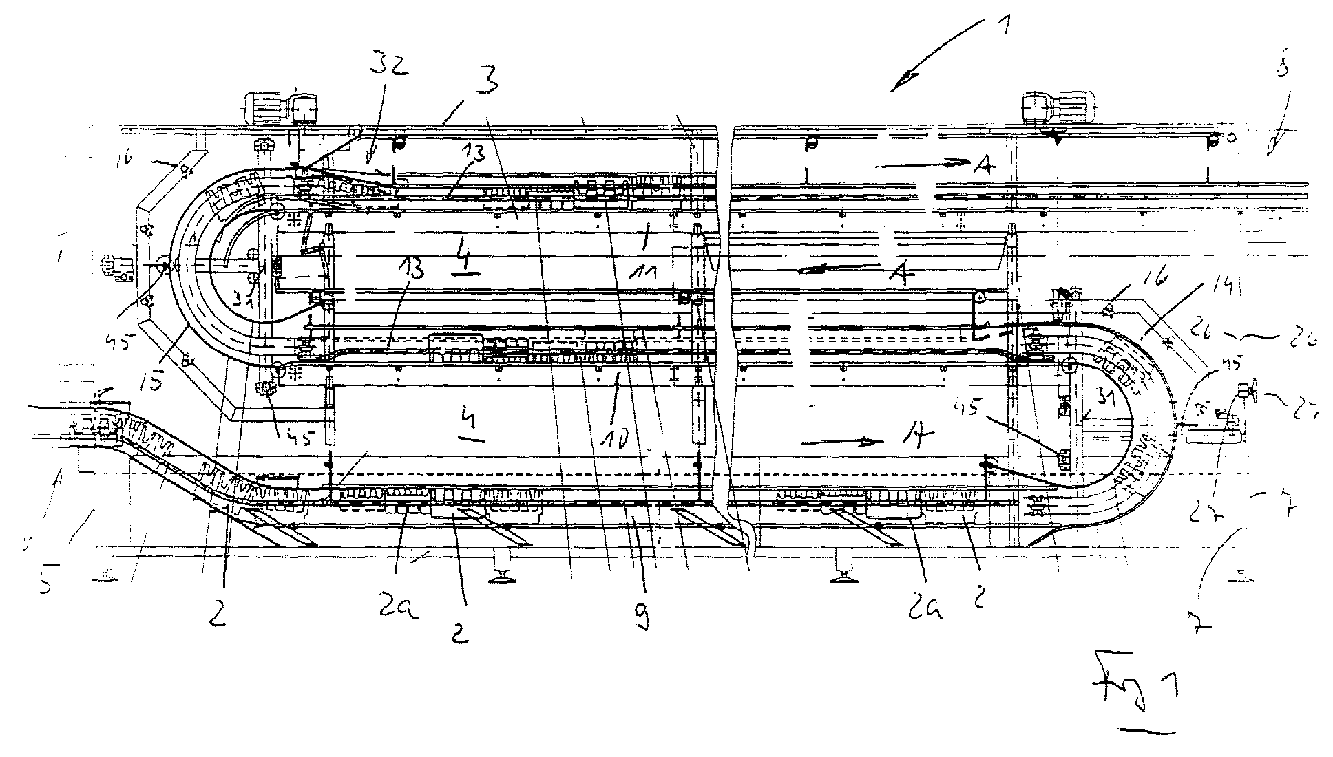
- Fig. 1
- in vereinfachter schematischer Darstellung und im Längsschnitt eine Flaschenkasten-Reinigungsmaschine gemäß der Erfindung;
- Fig. 2
- in vergrößerter Teildarstellung eine in der Höhe einstellbare und als Niederhalter dienende obere Führungsschiene;
- Fig. 3
- in vergrößerter Darstellung einen Schnitt entsprechend der Linie I - I der
Figur 2; - Fig. 4
- im Detail und in Seitenansicht eine der Umlenkrollen einer Verstellvorrichtung
für den Niederhalter der
Figur 2; - Fig. 5
- in Teildarstellung das obere Ende eines der beiden Wende- oder Aufwärtsförderer, zusammen mit einer einstellbaren unteren Kastenführung am Übergang zwischen dem Wende- oder Aufwärtsförderer und der anschließenden horizontalen Förderstrecke;
- Fig. 6
- einen Schnitt entsprechend der Linie II - II der Figur 5;
- Fig. 7
- in Teildarstellung eines der beiden einstellbaren seitlichen Führungsgeländer
einer horizontalen Förderstrecke der Reinigungsmaschine der
Figur 1.
- Fig. 1
- in a simplified schematic representation and in longitudinal section a bottle crate cleaning machine according to the invention;
- Fig. 2
- an enlarged partial representation of an upper guide rail which is adjustable in height and serves as a hold-down device;
- Fig. 3
- an enlarged view a section along the line I - I of Figure 2;
- Fig. 4
- in detail and in side view one of the deflection rollers of an adjusting device for the hold-down device of FIG. 2;
- Fig. 5
- in partial representation, the upper end of one of the two reversing or upward conveyors, together with an adjustable lower box guide at the transition between the reversing or upward conveyor and the subsequent horizontal conveyor line;
- Fig. 6
- a section along the line II - II of Figure 5;
- Fig. 7
- in partial representation of one of the two adjustable lateral guide rails of a horizontal conveyor path of the cleaning machine of FIG. 1.
Die in den Figuren dargestellte und dort allgemein mit 1 bezeichnete
Reinigungsmaschine dient zum Reinigen von Kästen 2 bzw. 2a, die zur Aufnahme von
Behältern, beispielsweise Flaschen (Kasten 2) oder Dosen (Kasten 2a) bestimmt sind.
Die Maschine 1 besteht im wesentlichen aus einem langgestreckten bzw.
quaderförmigen Gehäuse 3, welches einen Innenraum bzw. Behandlungsraum 4
umschließt, in dem die zum Waschen und Reinigen der Kästen 2 bzw. 2a
notwendigen Funktionselemente und Aggregate (insbesondere Tauchbad und
Spritzdüsen) untergebracht sind. Der Innenraum 4 ist beispielsweise durch nicht
dargestellte, an einer Längsseite des Gehäuses 3 vorgesehene großflächige, d.h.
mannshohe Türen mit großen Fenstern zugänglich, durch die die Arbeitsweise der
Maschine 1 einfach und übersichtlich überwachbar ist.The one shown in the figures and generally designated 1 there
Cleaning machine is used to clean
Zwischen einem an der in der Figur 1 linken Stirnseite 5 des Gehäuses 3 im unteren
Bereich vorgesehenen Kasteneinlauf 6 und einem an der in dieser Figur an der rechten
Stirnseite 7 im oberen Bereich vorgesehenen Kastenauslauf 8 ist eine bei der
dargestellten Ausführungsform einspurige Fördereinrichtung gebildet, auf der die zu
reinigenden Kästen 2 bzw. 2a durch den Innenraum 4 und an den an der
Fördereinrichtung gebildeten Behandlungs- bzw. Waschelementen vorbei bewegt
werden.Between one on the left in FIG. 1 end face 5 of the
Wie in der Figur 1 weiterhin dargestellt ist, besteht diese Fördereinrichtung im
wesentlichen aus drei in vertikaler Richtung etagenartig übereinander angeordneten
horizontalen Förderstrecken 9 - 11, auf denen die Kästen in Förderrichtung A bewegt
werden und von denen die unterste Förderstrecke 9 als Tauchbad ausgeführt ist, in
welchem die zu reinigenden Kästen 2 bzw. 2a in einer Reinigungsflüssigkeit
untergetauch werden. Die mittlere Transportstrecke 10 und die obere Transportstrecke
11 sind jeweils von eigenständigen, endlos umlaufend angetriebenen Förderketten 12
(Figur 6) gebildet, die mit ihrer oberen, horizontalen Länge jeweils eine Standfläche für
die Kästen 2 bzw. 2a bilden und die Transportebene TE der Transportstrecke
definieren.As is also shown in FIG. 1, this conveyor device consists of
essentially of three arranged vertically above one another in the vertical direction
horizontal conveyor lines 9 - 11, on which the boxes moved in the conveying direction A.
are and of which the
Die Förderstrecken 10 und 11 weisen weiterhin an den Längsseiten jeweils ein
seitliches Führungsgeländer 13 auf, welches sich in horizontaler Richtung entlang der
betreffenden Transportstrecke parallel zur Förderrichtung A erstreckt. Die als
Scharnierbandketten ausgebildeten Förderbänder 12 sind jeweils so angetrieben, daß
sich die notwendige Förderrichtung A für die Kästen 2 bzw. 2a ergibt, d.h. bei der für
die Figur 1 gewählten Darstellung an der Transportstrecke 10 von rechts nach links
und an der Transportstrecke 11 von links nach rechts.The
Zwischen der Transportstrecke 9 und der Transportstrecke 10 sowie der
Transportstrecke 10 und der Transportstrecke 11 ist jeweils ein Wende- oder
Aufwärtsförderer 14 bzw. 15 vorgesehen, in dem die Kästen 2 bzw. 2a gewendet
werden, so daß bei der dargestellten Ausführungsform die Kästen, die auf ihrem Boden
aufstehend dem Kasteneinlauf 6 zugeführt werden, die als Tauchbad ausgebildete
Transportstrecke 9 in dieser Orientierung durchlaufen, dann über den Aufwärtsförderer
14 gewendet, d.h. mit dem Kastenboden oben liegend an die Transportstrecke 10
übergeben werden und von dort über den Aufwärtsförderer 15 abermals gewendet,
wieder mit dem Boden unten liegend über die Transportstrecke 11 an den
Kastenauslauf 9 gelangen.Between the
An den Transportstrecken 10 und 11 sowie auch an den Aufwärtsförderern 14 und 15
sind zur Behandlung der Kästen unter anderem Spritzdüsen 16 für die jeweilige
Wasch- oder Behandlungsflüssigkeit (Wasser mit Reinigungszusätzen sowie
Frischwasser zum Klarspülen usw.) vorgesehen. On the
Die Aufwärtsförderer 14 und 15 sind jeweils als Klemmbackenförderer ausgebildet, in
denen die Kästen 2 bzw. 2a seitlich durch Klemmen an Klemmbacken gehalten sind,
die an umlaufend angetriebenen und an Rahmen oder Trägern 43 geführten
Klemmbackenbändern 44 vorgesehen sind (fig. 7). Derartige Klemmbackenförderer
sind dem Fachmann bekannt.The upward conveyors 14 and 15 are each designed as jaw conveyors, in
which the
An den Transportstrecken 10 und 11, aber auch an der Transportstrecke 9 ist jeweils
ein oberes, als Niederhalter dienendes Führungsgeländer (Führungsschiene) 17
vorgesehen, welches sich oberhalb der jeweiligen Transportstrecke in einer die
Transportrichtung A einschließenden vertikalen Mittelebene M vorgesehen ist.On the
Wie in der Figur 1 auch dargestellt ist, besitzen die Kästen 2 und 2a unterschiedliche
Größe und Höhe, wobei bei der dargestellten Ausführung die Kästen 2 übliche
Flaschenkästen zur Aufnahme von Getränkeflaschen und die Kästen 2a aus einem
geeigneten Material, beispielsweise aus Kunststoff hergestellte Trays zur Aufnahme von
Dosen sind.As also shown in Figure 1, the
Um mit ein und derselben Maschine Kästen unterschiedlicher Größe bzw. Höhe,
beispielsweise die Kästen 2 und 2a behandeln zu können, und hierfür ein schnelles
Umrüsten der Maschine 1 von einer Kastenhöhe auf eine andere Kastenhöhe zu
ermöglichen, sind die Führungsgeländer 17 über eine Einstellvorrichtung in der Höhe,
d.h. in vertikaler Richtung einstellbar, wie dies in den Figuren mit dem Doppelpfeil B
angedeutet ist.In order to use the same machine to make boxes of different sizes or heights,
For example, to be able to treat
Die für diese Höhenverstellung vorgesehene Verstellvorrichtung ist mehr im Detail in
den Figuren 2 und 3 wiedergegeben und dort allgemein mit 18 bezeichnet. Für jedes
Führungsgeländer 17 ist bei der dargestellten Ausführungsform eine eigene
Verstellvorrichtung 18 vorgesehen. Diese besteht jeweils im wesentlichen aus einer
oberen, als Stange ausgebildeten Hubschiene 19, die bei der dargestellten
Ausführungsform von einem C- oder U-Profil gebildet und oberhalb der zugehörigen
Führungsschiene 17 derart angeordnet ist, daß die offene Seite dieses Profils nach
unten, d.h. in Richtung auf die Führungsschiene 17 weist. Die Hubschiene 19, die mit
ihrer Längserstreckung parallel zur zugehörigen Führungsschiene 17 und gemeinsam
mit dieser in der Mittelebene M angeordnet ist, ist in Längsrichtung, d.h. in
horizontaler Richtung parallel zur Förderrichtung A um einen vorgegebenen Hub
(Doppelpfeil C) verschiebbar. Hierfür sind an einem Rahmen 20 des Gehäuses 3
mehrere Rollen 21 um Achsen senkrecht zur Mittelebene M frei drehbar gelagert, und
an von Rahmenelementen 20 nach unten wegstehenden flachen Armen 22. Auf diesen
Rollen 21 liegt die Schiene 19 auf, und zwar zwischen den Armen 22 und damit durch
diese gegen seitliches Herunterrutschen gesichert.The adjustment device provided for this height adjustment is in more detail in
Figures 2 and 3 reproduced and generally designated 18 there. For each
An der Verstell- oder Hubschiene 19 sind mehrere als Rollenketten ausgebildete Ketten
23 jeweils mit einem Ende befestigt, und zwar bei der dargestellten Ausführungsform
bei jeder Verstellvorrichtung 18 insgesamt drei Ketten in gleichmäßigen Abständen
derart, daß sich jeweils eine Kette 23 im Bereich jeden Endes der Schiene 19 bzw. der
zugehörigen Führungsschiene 17 und eine Kette 23 sich in der Mitte der jeweiligen
Schiene 19 bzw. Führungsschiene 17 befindet. Jede Kette 23 ist dabei mit ihrem
oberen Ende zwischen den Schenkeln des U- bzw. C-Profils der Hubschiene 19
gehalten (Befestigungspunkt 24) und über eine diesem Befestigungspunkt 24
benachbarte Rolle 21 geführt, so daß jede Kette 23 über diese Rolle 21 nach unten
hängt. Jede Kette 23 ist weiterhin mit ihrem unteren Ende bei 25 an der Oberseite der
zugehörigen Führungsschiene 17 befestigt.On the adjusting or lifting
Wie der Figur 1 zu entnehmen ist, erstrecken sich sämtliche Ketten 23 jeder Hub- oder
Verstelleinrichtung 18 jeweils gleichsinnig über die ihrem Befestigungspunkt 24
benachbarte Rolle 21, und zwar bei der für die Figur 1 gewählten Darstellung
ausgehend von dem oberen Befestigungspunkt 24 im Gegenuhrzeigersinn um etwa
einen Viertel Umfang der zugehörigen Rolle 21. Weiterhin ist die Anordnung so
getroffen, daß in der einen Endstellung des Hubes C, die der untersten Stellung der
Führungsschiene 17 entspricht, sich der obere Befestigungspunkt 24 an der Rolle 21
oder in unmittelbarer Nähe dieser Rolle befindet, während in der anderen
Extremstellung des Hubes C, die der oberen Stellung der Führungsschiene 17
entspricht, der obere Befestigungspunkt 24 von der zugehörigen Rolle 21 einen
größeren Abstand aufweist. In beiden Fällen ist die jeweilige Kette 23 über die
zugehörige Rolle 21 geführt.As can be seen in Figure 1, all
Die Ausbildung der Hubschiene 19 als C- oder U-Profil und die Befestigung der Ketten
23 im Inneren dieses Profils haben den Vorteil, daß die Hubschiene 19 auf den Rollen
21 aufliegt und über die gleichen Rollen 21 auch die Ketten 23 geführt sind. Anstelle
des C-Profils kann für die Hubschienen 19 auch ein anderes Profil, beispielsweise ein
Vollprofil oder ein Rohrprofil mit quadratischem oder rechteckförmigem Querschnitt
verwendet sein, wobei dieses Profil dann jeweils im Bereich der Rollen 21 mit einer
zur Unterseite hin offenen Ausnehmung für die Ketten 23 derart versehen ist, daß im
Bereich der Ausnehmung ein U- oder C-förmiger Querschnitt erhalten ist. Weiterhin ist
es möglich, die Rollen 21 jeweils mit einer Umfangsnut für die Ketten 23 zu versehen,
wobei die jeweilige Hubschiene dann seitlich von dieser Nut auf der Rolle aufliegt.The formation of the lifting
Über einen Antrieb, beispielsweise über einen Seilzug 26, kann die jeweilige
Hubschiene 19 in Richtung des Doppelpfeiles C durch Drehen an einem an der
Außenseite des Gehäuses 3 vorgesehenen Einstellrad 27 verschoben und damit die
Höhe der zugehörigen Führungsschiene 17 eingestellt werden. Bei der dargestellten
Ausführungsform ist für jede Verstellvorrichtungen 18 ein eigenes Einstellrad 27 mit
zugehörigem Antrieb bzw. Seilzug 26 vorgesehen. Grundsätzlich besteht aber auch die
Möglichkeit, sämtliche Verstellvorrichtungen 18 über ein gemeinsames Stellglied,
beispielsweise Einstellrad 27, zu betätigen. Selbstverständlich kann diese Einstellung
auch motorisch, beispielsweise durch einen Elektromotor oder ein anderes motorisches
Stellglied oder Antrieb erfolgen.Via a drive, for example a
Die Führungsschienen 17 liegen bei der dargestellten Ausführungsform dann, wenn die
Kästen 2 bzw. 2a gegen diese Führungsschienen zur Anlage kommen, mit ihrem
Massengewicht gegen die Kästen an und bestehen bei der dargestellten
Ausführungsform aus einem am Umfang geschlossenen Hohl- oder Rohrprofil mit
quadratischem Querschnitt.The guide rails 17 are in the illustrated embodiment when the
Zumindest an dem bezogen auf die Förderrichtung A vorderen Ende ist an jeder
Führungsschiene 17 eine kürzere Führungsschiene 17a mit einem Ende angelenkt
(Gelenk 28) und mit dem anderen Ende gelenkig (Gelenk 29) mit einem an dem
Gehäuse 3 bzw. an einem dortigen Rahmenteil 20 vorgesehenen Lager 30 verbunden,
und zwar derart, daß die Längserstreckung der Führungsschiene 17a der gemeinsamen
Mittelebene M mit der Längserstreckung der zugehörigen Führungsschiene 17 liegt.At least at the front end in relation to the conveying direction A is on everyone
Guide rail 17 a shorter guide rail 17a hinged at one end
(Joint 28) and articulated at the other end (joint 29) with one at the
Das Gelenk 28 ist so ausgebildet, daß es ein Schwenken zwischen den
Führungsschienen 17 und 17a um eine Achse senkrecht zur Mittelebene M ermöglicht.
Das am Lager 30 gebildete Gelenk 29 ist so ausgebildet, daß es ein Schwenken um
eine senkrecht zur Mittelebene M liegende Achse sowie gleichzeitig auch ein radiales
Verschieben in horizontaler Richtung ermöglicht. Bei der dargestellten
Ausführungsform ist das Gelenk 29 ein Stift-Schlitz-Gelenk.The joint 28 is designed so that there is a pivoting between the
Allows guide rails 17 and 17a about an axis perpendicular to the center plane M.
The joint 29 formed on the
Durch die Führungsschienen 17a wird zum einen verhindert, daß Flaschenkästen 2
bzw. 2a sich am Anfang der jeweiligen Führungsschiene 17 durch eventuelles
Anlaufen gegen das dortige Ende dieser Führungsschiene sperren könnten, d.h. durch
die Führungsschienen 17a werden die in die jeweilige Förderstrecke 9, 10 bzw. 11
einlaufenden Kästen 2 bzw. 2a also zuverlässig unter die zugehörige Führungsschiene
17 geleitet. Gleichzeitig wird durch die Führungsschienen 17a auch eine Stabilisierung
der zugehörigen Führungsschiene 17 erreicht, insbesondere auch gegen ein
unerwünschtes Pendeln um eine Achse parallel zur Förderrichtung A. Durch die
Gelenke 28 und 29 ist trotz der jeweiligen Führungsschiene 17a eine
Höhenverstellung der Führungsschiene 17 in der vorbeschriebenen Weise möglich.
Auch die Führungsschienen 17a bestehen jeweils aus einem Rohrprofil mit
quadratischem Querschnitt. On the one hand, the guide rails 17a prevent
Wie die Figur 1 zeigt, werden die Kästen 2, 2a, die eine sehr unterschiedliche Höhe
aufweisen können, von der Transportstrecke 10 an den anschließenden
Aufwärtsförderer 15 in einer Positionierung übergeben, die der Positionierung dieser
Kästen auf der Transportstrecke 10 entspricht, d.h. die Kästen sind mit ihrer offenen
Seite im Bereich des Aufwärtsförderers 15 außen liegend mit einem radialen Abstand
von der Mittelachse 31 der halbkreisförmigen Bewegungsbahn dieses
Aufwärtsförderers angeordnet, der (radiale Abstand) dem Abstand entspricht, den die
Transport- oder Förderebene der Transportstrecke 10 von dieser Mittelachse 31
aufweist. Die Transport- oder Förderebene der darüber liegenden Transportstrecke 11
besitzt aber einen wesentlich kleineren Abstand von der Mittelachse 31, wobei die
Differenz dieser Abstände etwas größer ist als die größte Höhe der zu verarbeitenden
Kästen.As Figure 1 shows, the
Um nicht nur die Kästen 2 größerer Höhe, sondern auch die Kästen 2a kleinerer Höhe
schonend und geräuscharm verarbeiten zu können, ist an dem Übergang zwischen
dem Aufwärtsförderer 15 und der Transportstrecke 11 eine einstellbare Kastenführung
32 vorgesehen, über die die Kästen 2 bzw. 2a mit ihrer Unterseite gleitend auf das
Förderband bzw. auf die Scharnierbandkette 12 der Transportstrecke 11 gelangen und
über die somit eine schonende und insbesondere auch geräuscharme Übergabe von
Kästen kleinerer Höhe, beispielsweise der Kästen 2a, erreicht wird.Not only the
Am Übergang zwischen dem Aufwärtsförderer 14 und der Transportstrecke 10 ist bei
der dargestellten Ausführungsform eine deratige Kastenführung 32 nicht erforderlich,
da davon ausgegangen wird, daß die Kästen 2 oder 2a beim Hindurchbewegen durch
die als Tauchbad ausgebildete Transportstrecke 9 in der dortigen Reinigungsflüssigkeit
aufschwimmen und über die dortige Führungsschiene 17 mit ihrer offenen Oberseite
auf einem Niveau gehalten werden, dessen Abstand von der Mittelachse 31 des
Aufwärtsförderers 14 gleich oder etwa gleich demjenigen Abstand ist, den die
Transportebene der Transportstrecke 10 von dieser Mittelachse 31 aufweist.
Grundsätzlich besteht aber die Möglichkeit, auch am Übergang zwischen dem
Aufwärtsförderer 14 und der Transportstrecke 10 eine derartige Kastenführung 32
vorzusehen.At the transition between the up conveyor 14 and the
Die Kastenführung 32 besteht im wesentlichen aus zwei von jeweils einem Rohrprofil
gebildeten Gleitschiene 33, die jeweils an einem Ende mittels eines Gelenks 34 an
einen Rahmen 35 der Transportstrecke 11 angelenkt sind, und zwar schwenkbar um
eine horizontale Achse senkrecht zur Mittelebene M bzw. zur Transportrichtung A.
Der Rahmen 35 bildet die Führung für die Scharnierbandkette 12 sowie die Lagerung
für die Führungs- und Umlenkräder dieser Kette.The
Die Gelenke 34 der beiden Gleitschienen 33 sind achsgleich angeordnet. Mit ihren
freien, gebogenen Enden reichen die Gleitschienen 33 in den Aufwärtsförderer 15
hinein. Die Gleitschienen 33 sind beidseitig von der Scharnierbandkette 12
vorgesehen. Etwa in der Mitte sind die beiden Gleitschienen 33 an der Unterseite über
einen Quersteg 36 verbunden, der mit seiner Längserstreckung parallel zur Achse der
Gelenke 34 liegt. An den Enden des Quersteges 36 ist jeweils mittels eines Gelenks 37
ein Hebel 38 mit einem Ende angelenkt, dessen anderes Ende mittels eines Gelenks 39
an einem Arm 40' eines Winkelhebels 40 angelenkt ist. Der Winkelhebel 40 ist mittels
eines Gelenkes 41 an einem Rahmenteil 20 des Gehäuses 3 angelenkt. Das freie Ende
des anderen Armes 40" des Winkelhebels 40 ist über ein Zugglied 42 mit der
Hubschiene 19 derjenigen Verstellvorrichtung 18 verbunden, mit der die
Höhenverstellung der Führungsschiene 17 der darunter liegenden Transportstrecke 10
erfolgt.The
Der Hebel 38 sowie die Arme 40' und 42" des Winkelhebels 40 liegen in einer Ebene
parallel zur Mittelebene M. Die Gelenke 37, 39 und 41 liegen mit ihren Gelenkachsen
senkrecht zu dieser Mittelebene. Die Anordnung ist weiterhin so getroffen, daß beim
Verstellen der Hubschiene 19 für die Führungsschiene 17 der Transportstrecke 10 im
Sinne eines Absenkens dieser Führungsschiene 17 die beiden Gleitschienen 33 um die
Gelenke 34 mit ihren freien Enden nach oben geschwenkt werden bzw. bei einem
Anheben der angesprochenen Führungsschiene 17 ein Schwenken der Gleitschienen
33 nach unten erfolgt. Hiermit wird also in Abhängigkeit von der Einstellung der
Führungsschiene 17 der dem Aufwärtsförderer 15 vorausgehenden Transportstrecke 10
die am Ausgang des Aufwärtsförderers 15 vorgesehene Kastenführung 32 selbsttätig
richtig auf die Höhe der Kästen 2 bzw. 2a derart eingestellt, daß der Abstand der freien
Enden der Gleitschienen 33 von der Mittelachse 31 etwa gleich oder geringfügig
größer ist als der Abstand der mit verstellten Führungsschiene 17 der Transprtstrecke
10 von der zugehörigen Transportebene TE und somit die innerhalb des
Aufwärtsförderers 15 noch gehaltenen Kästen vor der Übergabe an die Transportstrecke
11 mit ihrem Boden auf die gekrümmten Enden der Gleitschienen 33 aufgleiten und
dann entlang dieser Gleitschienen 33 schonend und nahezu geräuschlos auf die
Transportstrecke 11 gelangen.The
Die Einstellung der Kastenführung 32 erfolgt also über das gemeinsame Einstellelement
für die Höheneinstellung der Führungsschiene 17 der Kastenführung 32 in
Transportrichtung A vorausgehenden Transportstrecke 10.The setting of the
Um Kästen 2 bzw. 2a verarbeiten zu können, die in horizontaler Richtung und quer
zur Förderrichtung A unterschiedliche Breite aufweisen, ist es üblich und bekannt, die
Förderbreite der Aufwärtsförderer 14 bzw. 15 einzustellen, und zwar jeweils durch
Verstellen der beiden Rahmenteile 43 des jeweiligen Aufwärtsförderers senkrecht und
symmetrisch zur Mittelebene M. An den Rahmenteilen 43 sind die die Klemmbacken
bildenden Transportbänder 44 geführt. Diese Verstellung erfolgt über Spindeln 45, die
über einen gemeinsamen Antrieb betätigbar sind, beispielsweise über einen manuellen
Antrieb an der Außenseite des Gehäuses 3. Um beim Verstellen der Förderbreite der
Aufwärtsförderer 14 und 15 zugleich auch eine Breitenverstellung zumindest der
Transportstrecken 10 und 11 bzw. der dortigen Führungsgeländer 13 zu erreichen, ist
jedes Führungsgeländer 13 beidendig über eine Hebelanordnung 46 mit einem
Rahmenelement 43 antriebsmäßig verbunden.To be able to process
Die Hebelanordnung 46 besteht aus einem Hebel 47, der über die der jeweiligen
Transportstrecke 10 bzw. 11 abgewandte Außenseite des Führungsgeländers 13 schräg
wegsteht und an einem Ende mittels eines Gelenkes 48 am Führungsgeländer und am
anderen Ende mittels eines Gelenks 49 an einem Rahmenteil 20 des Gehäuses 3
angelenkt ist. In der Mitte ist der Hebel 47 über ein Gelenk 50 mit einem Ende eines
Steuerhebels 51 verbunden, dessen anderes Ende über ein Gelenk 52 mit dem
Rahmenteil 43 gelenkig verbunden ist. Die Gelenkachsen der Gelenke 48, 49, 50 und
52 sind jeweils vertikale Achsen. Bei der Verstellung der Förderbreite der
Aufwärtsförderer 14 bzw. 15 (Doppelpfeil D) wird über den Steuerhebel 51 der
zugehörige Hebel 47 für eine Breitenverstellung des seitlichen Führungsgeländers 13
geschwenkt. Über mehrere, dem Hebel 47 entsprechende Hebel 47a ist das
Führungsgeländer 13 zwischen seinen beiden Enden im Gehäuse 3 abgestützt.The
Wie auch die übrigen, im Innenraum 4 vorgesehenen Funktionselemente, sind
insbesondere die Führungsschienen 17, 17a sowie die Elemente der
Verstellvorrichtung 18, der Kastenführung 32 sowie die Elemente der
Hebelanordnungen 46 aus korrosionsbeständigem Material hergestellt, vorzugsweise
aus Edelstahl oder korrosionsbeständigem Stahl. Die Rollen 21 der
Verstellvorrichtungen 18 bestehen vorzugsweise aus einem geeigneten Kunststoff.Like the other functional elements provided in the interior 4, are
in particular the guide rails 17, 17a and the elements of the
Die Erfindung wurde voranstehend an einem Ausführungsbeispiel beschrieben. Es versteht sich, daß zahlreiche Änderungen sowie Abwandlungen möglich sind, ohne daß dadurch der der Erfindung zugrundeliegende Erfindungsgedanke verlassen wird. The invention has been described above using an exemplary embodiment. It it goes without saying that numerous changes and modifications are possible without that this leaves the inventive idea on which the invention is based.
- 11
- Reinigungs- oder WaschmaschineCleaning or washing machine
- 2, 2a2, 2a
- Kastenbox
- 33
- Gehäusecasing
- 44
- Innenrauminner space
- 55
- Stirnseitefront
- 66
- Kasteneinlaufbox inlet
- 77
- Stirnseitefront
- 88th
- Kastenauslaufbox outlet
- 9, 10, 119, 10, 11
- Transportstrecketransport distance
- 1212
- Förderband bzw. ScharnierbandketteConveyor belt or hinge chain
- 1313
- Führungsgeländerguide railings
- 14, 1514, 15
- Aufwärtsfördererupward conveyor
- 1616
- Spritzdüsenozzle
- 17, 17a17, 17a
- Führungsschieneguide rail
- 1818
- Verstell- oder HubvorrichtungAdjustment or lifting device
- 1919
- Hubschienelifting rail
- 2020
- Rahmenelementframe element
- 2121
- Rollerole
- 2222
- Armpoor
- 2323
- KetteChain
- 24, 2524, 25
- Befestigungspunktattachment point
- 2626
- Seilrope
- 2727
- Einstellraddial
- 28, 2928, 29
- Gelenkjoint
- 3030
- Lagercamp
- 3131
- Mittelachsecentral axis
- 3232
- Kastenführungbox guide
- 3333
- Gleitschieneslide
- 3434
- Gelenk joint
- 3535
- Rahmenframe
- 3636
- Querstrebecrossmember
- 3737
- Gelenkjoint
- 3838
- Hebellever
- 3939
- Gelenkjoint
- 4040
- Winkelhebelbell crank
- 40', 40"40 ', 40 "
- Armpoor
- 4141
- Gelenkjoint
- 4242
- Zuggliedtension member
- 4343
- Rahmenframe
- 4444
- Transport- oder KlemmbackenbandTransport or clamping band
- 4545
- Verstellspindeladjusting spindle
- 4646
- Hebelanordnunglever assembly
- 47, 47a47, 47a
- Hebellever
- 48, 49, 5048, 49, 50
- Gelenkjoint
- 5151
- Steuerhebelcontrol lever
- 5252
- Gelenkjoint
- AA
- Förderrichtungconveying direction
- B, C, DB, C, D
- Doppelpfeildouble arrow
- MM
- Mittelebene TE Transportebenemidplane TE transport plane
Claims (13)
wobei das Hubelement (19) beispielsweise in einer Achsrichtung parallel zur Transportrichtung (A) für die Verstellung des Führungselementes (17, 17a) bewegbar ist, und/oder
wobei beispielsweise am Hubelement (19) wenigstens zwei Verbindungsglieder (23) mit einem Ende gehalten sind, die mit ihrem anderen Ende an dem Führungselement (17) befestigt sind und von denen jedes Verbindungsglied (23) über wenigstens ein mit dem Hubelement (19) nicht mitbewegtes Umlenkelement (21) geführt ist.Device according to one of the preceding claims, characterized in that the adjusting or lifting device (18) has at least one lifting or pushing element, for example in the form of a rail (19), which extends on the side of the guide element (17) facing away from the conveying plane, that the guide element (17) is held on the lifting element (19) by means of at least one connecting member (23) formed by a chain, a belt, a rope, a band or the like, ) or a guide element provided on a frame element (20), for example guided over at least one roller (21) such that when the lifting element (19) is moved in the longitudinal direction relative to the at least one deflection element (21), the adjusting element (23) adjusts the guide element (17) takes place relative to the transport plane,
the lifting element (19) being movable, for example, in an axial direction parallel to the transport direction (A) for the adjustment of the guide element (17, 17a), and / or
wherein, for example, at least two connecting links (23) are held at one end on the lifting element (19), the other ends of which are attached to the guide element (17) and of which each connecting link (23) does not have at least one with the lifting element (19) moving deflection element (21) is guided.
daß das Hubelement (19) einen U- oder C-förmigen Querschnitt besitzt, und/oder daß das wenigstens eine Umlenkelement (21) zumindest eine Ausnehmung, beispielsweise eine nutenförmige Ausnehmung zur Aufnahme des Verbindungsgliedes (23) und außerhalb der Ausnehmung wenigstens eine Anlagefläche für das Hubelement (19) aufweist.Device according to one of the preceding claims, characterized in that the lifting element (19), at least in the region in which it rests on the deflecting element (21) via its adjusting stroke, has a recess which is open at least towards this deflecting element (21), within the one end of the connecting member (23) is attached, and / or
that the lifting element (19) has a U-shaped or C-shaped cross section, and / or that the at least one deflection element (21) has at least one recess, for example a groove-shaped recess for receiving the connecting member (23) and outside the recess at least one contact surface for the lifting element (19).
daß das Gleitelement (33) an seinem anderen Ende um eine Achse senkrecht zur Förderrichtung (A) und parallel zur Transportebene schwenkbar gehalten ist.Device according to one of the preceding claims, characterized in that the sliding element (33) is adjustable at one end by the second adjusting device (38, 40) at least in one axial direction perpendicular to the transport plane relative to the latter, and / or
that the sliding element (33) is held at its other end about an axis perpendicular to the conveying direction (A) and parallel to the transport plane.
Applications Claiming Priority (2)
| Application Number | Priority Date | Filing Date | Title |
|---|---|---|---|
| DE20011170U DE20011170U1 (en) | 2000-06-30 | 2000-06-30 | Device for cleaning boxes |
| DE20011170U | 2000-06-30 |
Publications (3)
| Publication Number | Publication Date |
|---|---|
| EP1166902A2 true EP1166902A2 (en) | 2002-01-02 |
| EP1166902A3 EP1166902A3 (en) | 2003-07-09 |
| EP1166902B1 EP1166902B1 (en) | 2006-08-02 |
Family
ID=7943226
Family Applications (1)
| Application Number | Title | Priority Date | Filing Date |
|---|---|---|---|
| EP01115069A Expired - Lifetime EP1166902B1 (en) | 2000-06-30 | 2001-06-21 | Device for cleaning crates |
Country Status (3)
| Country | Link |
|---|---|
| EP (1) | EP1166902B1 (en) |
| AT (1) | ATE334752T1 (en) |
| DE (2) | DE20011170U1 (en) |
Cited By (1)
| Publication number | Priority date | Publication date | Assignee | Title |
|---|---|---|---|---|
| CN118543614A (en) * | 2023-02-24 | 2024-08-27 | 克朗斯股份公司 | Device for cleaning containers and method for operating the device |
Family Cites Families (7)
| Publication number | Priority date | Publication date | Assignee | Title |
|---|---|---|---|---|
| US2744531A (en) * | 1951-12-17 | 1956-05-08 | Dole Eng Co James | Container washing apparatus |
| JPH07112894B2 (en) * | 1986-10-31 | 1995-12-06 | 株式会社小松製作所 | Turnover device |
| DE4038239C2 (en) | 1990-11-30 | 1993-11-25 | Kettner Verpackungsmaschf | Device for turning reusable containers |
| DE4400871C2 (en) * | 1993-09-19 | 2000-11-02 | Ludwig Bohrer | Device for washing or cleaning bottle crates |
| DE19542457C1 (en) | 1995-11-14 | 1997-04-03 | Bohrer Maschinenbau Gmbh | Cleaning equipment for industrial containers |
| JPH09295610A (en) * | 1996-05-02 | 1997-11-18 | Shin Etsu Polymer Co Ltd | Long-item-aligning device |
| DE10017290C2 (en) | 2000-04-07 | 2002-04-18 | Holzmann Wilhelm | Device and method for cleaning transport containers |
-
2000
- 2000-06-30 DE DE20011170U patent/DE20011170U1/en not_active Expired - Lifetime
-
2001
- 2001-06-21 DE DE50110587T patent/DE50110587D1/en not_active Expired - Lifetime
- 2001-06-21 AT AT01115069T patent/ATE334752T1/en not_active IP Right Cessation
- 2001-06-21 EP EP01115069A patent/EP1166902B1/en not_active Expired - Lifetime
Cited By (2)
| Publication number | Priority date | Publication date | Assignee | Title |
|---|---|---|---|---|
| CN118543614A (en) * | 2023-02-24 | 2024-08-27 | 克朗斯股份公司 | Device for cleaning containers and method for operating the device |
| EP4420801A1 (en) * | 2023-02-24 | 2024-08-28 | Krones AG | Device for cleaning containers and method for operating the device |
Also Published As
| Publication number | Publication date |
|---|---|
| EP1166902A3 (en) | 2003-07-09 |
| EP1166902B1 (en) | 2006-08-02 |
| DE50110587D1 (en) | 2006-09-14 |
| ATE334752T1 (en) | 2006-08-15 |
| DE20011170U1 (en) | 2001-03-01 |
Similar Documents
| Publication | Publication Date | Title |
|---|---|---|
| EP0721808B1 (en) | Cleaning machine for containers | |
| DE3789149T2 (en) | Conveyor. | |
| DE2943769C2 (en) | ||
| EP1059225B1 (en) | Method and apparatus for conveying vehicle bodies through a processing bath | |
| EP0485937A1 (en) | Grouping device | |
| EP1383696A1 (en) | Conveyor device for transporting workpieces through a processing area for surface treatment of said workpieces | |
| DE3016940A1 (en) | Orientating oblong-section containers on moving conveyor - using endless friction belts to either side moving forward at different speeds | |
| DE10210942B4 (en) | Plant for treating, in particular for cataphoretic dip painting, objects, in particular vehicle bodies | |
| DE3137623C1 (en) | ||
| DE4400871C2 (en) | Device for washing or cleaning bottle crates | |
| DE19513221A1 (en) | Vessel cleaning machine | |
| EP1166902B1 (en) | Device for cleaning crates | |
| DE4330702A1 (en) | Adjustable railing support and conveying stage with an adjustable railing | |
| DE4027433A1 (en) | METHOD AND DEVICE FOR ROTATING AN OBJECT | |
| EP1059223A1 (en) | Skids for conveying workpieces, in particular vehicle bodies, and rotating device for rotating said skids | |
| EP2342150B1 (en) | Endless conveyor with a device for cleaning the conveyor | |
| DE2531507C2 (en) | Device for sorting and classifying live fish | |
| DE60100214T2 (en) | Swivel station for the conveyor device of a treatment plant | |
| DE2825741A1 (en) | Material roll loading machine - has bar hooks on chains with locking members released at transfer position | |
| CH645142A5 (en) | Apparatus for the retention treatment of a broad-guided textile web | |
| DE10331982B4 (en) | Plant for cleaning boxes, in particular crates | |
| DE8909050U1 (en) | Machine for cleaning bottle crates | |
| DE8435932U1 (en) | DEVICE FOR WASHING BOTTLE BOXES | |
| DE20112237U1 (en) | Device for cleaning bottle crates | |
| DE9113313U1 (en) | Device for cleaning bottle crates |
Legal Events
| Date | Code | Title | Description |
|---|---|---|---|
| PUAI | Public reference made under article 153(3) epc to a published international application that has entered the european phase |
Free format text: ORIGINAL CODE: 0009012 |
|
| AK | Designated contracting states |
Kind code of ref document: A2 Designated state(s): AT BE CH CY DE DK ES FI FR GB GR IE IT LI LU MC NL PT SE TR |
|
| AX | Request for extension of the european patent |
Free format text: AL;LT;LV;MK;RO;SI |
|
| PUAL | Search report despatched |
Free format text: ORIGINAL CODE: 0009013 |
|
| AK | Designated contracting states |
Designated state(s): AT BE CH CY DE DK ES FI FR GB GR IE IT LI LU MC NL PT SE TR |
|
| AX | Request for extension of the european patent |
Extension state: AL LT LV MK RO SI |
|
| 17P | Request for examination filed |
Effective date: 20030808 |
|
| AKX | Designation fees paid |
Designated state(s): AT BE CH CY DE DK ES FI FR GB GR IE IT LI LU MC NL PT SE TR |
|
| GRAP | Despatch of communication of intention to grant a patent |
Free format text: ORIGINAL CODE: EPIDOSNIGR1 |
|
| GRAS | Grant fee paid |
Free format text: ORIGINAL CODE: EPIDOSNIGR3 |
|
| GRAA | (expected) grant |
Free format text: ORIGINAL CODE: 0009210 |
|
| AK | Designated contracting states |
Kind code of ref document: B1 Designated state(s): AT BE CH CY DE DK ES FI FR GB GR IE IT LI LU MC NL PT SE TR |
|
| PG25 | Lapsed in a contracting state [announced via postgrant information from national office to epo] |
Ref country code: IT Free format text: LAPSE BECAUSE OF FAILURE TO SUBMIT A TRANSLATION OF THE DESCRIPTION OR TO PAY THE FEE WITHIN THE PRESCRIBED TIME-LIMIT;WARNING: LAPSES OF ITALIAN PATENTS WITH EFFECTIVE DATE BEFORE 2007 MAY HAVE OCCURRED AT ANY TIME BEFORE 2007. THE CORRECT EFFECTIVE DATE MAY BE DIFFERENT FROM THE ONE RECORDED. Effective date: 20060802 Ref country code: IE Free format text: LAPSE BECAUSE OF FAILURE TO SUBMIT A TRANSLATION OF THE DESCRIPTION OR TO PAY THE FEE WITHIN THE PRESCRIBED TIME-LIMIT Effective date: 20060802 Ref country code: NL Free format text: LAPSE BECAUSE OF FAILURE TO SUBMIT A TRANSLATION OF THE DESCRIPTION OR TO PAY THE FEE WITHIN THE PRESCRIBED TIME-LIMIT Effective date: 20060802 Ref country code: FI Free format text: LAPSE BECAUSE OF FAILURE TO SUBMIT A TRANSLATION OF THE DESCRIPTION OR TO PAY THE FEE WITHIN THE PRESCRIBED TIME-LIMIT Effective date: 20060802 Ref country code: GB Free format text: LAPSE BECAUSE OF FAILURE TO SUBMIT A TRANSLATION OF THE DESCRIPTION OR TO PAY THE FEE WITHIN THE PRESCRIBED TIME-LIMIT Effective date: 20060802 |
|
| REG | Reference to a national code |
Ref country code: GB Ref legal event code: FG4D Free format text: NOT ENGLISH |
|
| REG | Reference to a national code |
Ref country code: CH Ref legal event code: EP |
|
| REG | Reference to a national code |
Ref country code: IE Ref legal event code: FG4D Free format text: LANGUAGE OF EP DOCUMENT: GERMAN |
|
| REF | Corresponds to: |
Ref document number: 50110587 Country of ref document: DE Date of ref document: 20060914 Kind code of ref document: P |
|
| PG25 | Lapsed in a contracting state [announced via postgrant information from national office to epo] |
Ref country code: DK Free format text: LAPSE BECAUSE OF FAILURE TO SUBMIT A TRANSLATION OF THE DESCRIPTION OR TO PAY THE FEE WITHIN THE PRESCRIBED TIME-LIMIT Effective date: 20061102 Ref country code: SE Free format text: LAPSE BECAUSE OF FAILURE TO SUBMIT A TRANSLATION OF THE DESCRIPTION OR TO PAY THE FEE WITHIN THE PRESCRIBED TIME-LIMIT Effective date: 20061102 |
|
| PG25 | Lapsed in a contracting state [announced via postgrant information from national office to epo] |
Ref country code: ES Free format text: LAPSE BECAUSE OF FAILURE TO SUBMIT A TRANSLATION OF THE DESCRIPTION OR TO PAY THE FEE WITHIN THE PRESCRIBED TIME-LIMIT Effective date: 20061113 |
|
| NLV1 | Nl: lapsed or annulled due to failure to fulfill the requirements of art. 29p and 29m of the patents act | ||
| PG25 | Lapsed in a contracting state [announced via postgrant information from national office to epo] |
Ref country code: PT Free format text: LAPSE BECAUSE OF FAILURE TO SUBMIT A TRANSLATION OF THE DESCRIPTION OR TO PAY THE FEE WITHIN THE PRESCRIBED TIME-LIMIT Effective date: 20070102 |
|
| GBV | Gb: ep patent (uk) treated as always having been void in accordance with gb section 77(7)/1977 [no translation filed] |
Effective date: 20060802 |
|
| REG | Reference to a national code |
Ref country code: IE Ref legal event code: FD4D |
|
| EN | Fr: translation not filed | ||
| PLBE | No opposition filed within time limit |
Free format text: ORIGINAL CODE: 0009261 |
|
| STAA | Information on the status of an ep patent application or granted ep patent |
Free format text: STATUS: NO OPPOSITION FILED WITHIN TIME LIMIT |
|
| 26N | No opposition filed |
Effective date: 20070503 |
|
| BERE | Be: lapsed |
Owner name: BOHRER, LUDWIG Effective date: 20070630 |
|
| PG25 | Lapsed in a contracting state [announced via postgrant information from national office to epo] |
Ref country code: MC Free format text: LAPSE BECAUSE OF NON-PAYMENT OF DUE FEES Effective date: 20070630 |
|
| REG | Reference to a national code |
Ref country code: CH Ref legal event code: PL |
|
| PG25 | Lapsed in a contracting state [announced via postgrant information from national office to epo] |
Ref country code: BE Free format text: LAPSE BECAUSE OF NON-PAYMENT OF DUE FEES Effective date: 20070630 |
|
| PG25 | Lapsed in a contracting state [announced via postgrant information from national office to epo] |
Ref country code: CH Free format text: LAPSE BECAUSE OF NON-PAYMENT OF DUE FEES Effective date: 20070630 Ref country code: FR Free format text: LAPSE BECAUSE OF FAILURE TO SUBMIT A TRANSLATION OF THE DESCRIPTION OR TO PAY THE FEE WITHIN THE PRESCRIBED TIME-LIMIT Effective date: 20070511 Ref country code: GR Free format text: LAPSE BECAUSE OF FAILURE TO SUBMIT A TRANSLATION OF THE DESCRIPTION OR TO PAY THE FEE WITHIN THE PRESCRIBED TIME-LIMIT Effective date: 20061103 Ref country code: LI Free format text: LAPSE BECAUSE OF NON-PAYMENT OF DUE FEES Effective date: 20070630 |
|
| PG25 | Lapsed in a contracting state [announced via postgrant information from national office to epo] |
Ref country code: AT Free format text: LAPSE BECAUSE OF NON-PAYMENT OF DUE FEES Effective date: 20070621 |
|
| PG25 | Lapsed in a contracting state [announced via postgrant information from national office to epo] |
Ref country code: FR Free format text: LAPSE BECAUSE OF FAILURE TO SUBMIT A TRANSLATION OF THE DESCRIPTION OR TO PAY THE FEE WITHIN THE PRESCRIBED TIME-LIMIT Effective date: 20060802 |
|
| PG25 | Lapsed in a contracting state [announced via postgrant information from national office to epo] |
Ref country code: LU Free format text: LAPSE BECAUSE OF NON-PAYMENT OF DUE FEES Effective date: 20070621 Ref country code: CY Free format text: LAPSE BECAUSE OF FAILURE TO SUBMIT A TRANSLATION OF THE DESCRIPTION OR TO PAY THE FEE WITHIN THE PRESCRIBED TIME-LIMIT Effective date: 20060802 |
|
| PG25 | Lapsed in a contracting state [announced via postgrant information from national office to epo] |
Ref country code: TR Free format text: LAPSE BECAUSE OF FAILURE TO SUBMIT A TRANSLATION OF THE DESCRIPTION OR TO PAY THE FEE WITHIN THE PRESCRIBED TIME-LIMIT Effective date: 20060802 |
|
| PGFP | Annual fee paid to national office [announced via postgrant information from national office to epo] |
Ref country code: DE Payment date: 20180731 Year of fee payment: 18 |
|
| REG | Reference to a national code |
Ref country code: DE Ref legal event code: R119 Ref document number: 50110587 Country of ref document: DE |
|
| PG25 | Lapsed in a contracting state [announced via postgrant information from national office to epo] |
Ref country code: DE Free format text: LAPSE BECAUSE OF NON-PAYMENT OF DUE FEES Effective date: 20200101 |