EP1166018B1 - Cassette type air conditioner for mounting in the ceiling - Google Patents
Cassette type air conditioner for mounting in the ceiling Download PDFInfo
- Publication number
- EP1166018B1 EP1166018B1 EP01901429A EP01901429A EP1166018B1 EP 1166018 B1 EP1166018 B1 EP 1166018B1 EP 01901429 A EP01901429 A EP 01901429A EP 01901429 A EP01901429 A EP 01901429A EP 1166018 B1 EP1166018 B1 EP 1166018B1
- Authority
- EP
- European Patent Office
- Prior art keywords
- bell
- mouth
- electrical parts
- air conditioner
- type air
- Prior art date
- Legal status (The legal status is an assumption and is not a legal conclusion. Google has not performed a legal analysis and makes no representation as to the accuracy of the status listed.)
- Expired - Lifetime
Links
Images


Classifications
-
- F—MECHANICAL ENGINEERING; LIGHTING; HEATING; WEAPONS; BLASTING
- F24—HEATING; RANGES; VENTILATING
- F24F—AIR-CONDITIONING; AIR-HUMIDIFICATION; VENTILATION; USE OF AIR CURRENTS FOR SCREENING
- F24F13/00—Details common to, or for air-conditioning, air-humidification, ventilation or use of air currents for screening
- F24F13/20—Casings or covers
-
- F—MECHANICAL ENGINEERING; LIGHTING; HEATING; WEAPONS; BLASTING
- F24—HEATING; RANGES; VENTILATING
- F24F—AIR-CONDITIONING; AIR-HUMIDIFICATION; VENTILATION; USE OF AIR CURRENTS FOR SCREENING
- F24F1/00—Room units for air-conditioning, e.g. separate or self-contained units or units receiving primary air from a central station
- F24F1/0007—Indoor units, e.g. fan coil units
- F24F1/0043—Indoor units, e.g. fan coil units characterised by mounting arrangements
- F24F1/0047—Indoor units, e.g. fan coil units characterised by mounting arrangements mounted in the ceiling or at the ceiling
-
- F—MECHANICAL ENGINEERING; LIGHTING; HEATING; WEAPONS; BLASTING
- F24—HEATING; RANGES; VENTILATING
- F24F—AIR-CONDITIONING; AIR-HUMIDIFICATION; VENTILATION; USE OF AIR CURRENTS FOR SCREENING
- F24F1/00—Room units for air-conditioning, e.g. separate or self-contained units or units receiving primary air from a central station
- F24F1/0007—Indoor units, e.g. fan coil units
- F24F1/0018—Indoor units, e.g. fan coil units characterised by fans
- F24F1/0022—Centrifugal or radial fans
-
- F—MECHANICAL ENGINEERING; LIGHTING; HEATING; WEAPONS; BLASTING
- F24—HEATING; RANGES; VENTILATING
- F24F—AIR-CONDITIONING; AIR-HUMIDIFICATION; VENTILATION; USE OF AIR CURRENTS FOR SCREENING
- F24F13/00—Details common to, or for air-conditioning, air-humidification, ventilation or use of air currents for screening
- F24F13/02—Ducting arrangements
- F24F13/06—Outlets for directing or distributing air into rooms or spaces, e.g. ceiling air diffuser
- F24F2013/0616—Outlets that have intake openings
-
- F—MECHANICAL ENGINEERING; LIGHTING; HEATING; WEAPONS; BLASTING
- F24—HEATING; RANGES; VENTILATING
- F24F—AIR-CONDITIONING; AIR-HUMIDIFICATION; VENTILATION; USE OF AIR CURRENTS FOR SCREENING
- F24F13/00—Details common to, or for air-conditioning, air-humidification, ventilation or use of air currents for screening
- F24F13/20—Casings or covers
- F24F2013/207—Casings or covers with control knobs; Mounting controlling members or control units therein
-
- Y—GENERAL TAGGING OF NEW TECHNOLOGICAL DEVELOPMENTS; GENERAL TAGGING OF CROSS-SECTIONAL TECHNOLOGIES SPANNING OVER SEVERAL SECTIONS OF THE IPC; TECHNICAL SUBJECTS COVERED BY FORMER USPC CROSS-REFERENCE ART COLLECTIONS [XRACs] AND DIGESTS
- Y10—TECHNICAL SUBJECTS COVERED BY FORMER USPC
- Y10S—TECHNICAL SUBJECTS COVERED BY FORMER USPC CROSS-REFERENCE ART COLLECTIONS [XRACs] AND DIGESTS
- Y10S62/00—Refrigeration
- Y10S62/16—Roof and ceiling located coolers
Definitions
- the present invention is concerned with ceiling cassette type air conditioner mounted to the ceiling of the room to be air conditioned, and in particular, it relates to the improvement of the mounting of temperature sensor that detects the temperature of the room air which is sucked in and guided by the bell-mouth, and the improvement of the arrangement of electrical parts box versus the bell-mouth as well as the mounting structure of the electrical parts in the electrical parts box.
- the ceiling cassette type air conditioner comprises an enclosure which is open at the bottom, a blower located at approximately the center of this enclosure, heat exchangers arranged around the blower, a bell-mouth that is installed so that its upper opening portion is facing the axial direction of the blower, and a decorative panel exposed to the room to be air conditioned from the ceiling surface, and which possesses a suction inlet facing the bottom opening portion of the bell-mouth, and which possesses blower outlets around the suction inlet, and blocks the lower opening portion of the enclosure.
- control motor-driven parts such as a blower
- electrical parts that receive detection signals such as remote controller (remote control operating panel) as well as operation instruction signals transmitted from various detection means, and change them into control signals.
- detection signals such as remote controller (remote control operating panel) as well as operation instruction signals transmitted from various detection means, and change them into control signals.
- the electrical parts consist of many electric parts and electronic parts, and because of the limited space in the enclosure, the electric parts are attached to a single control board, and after making electrical connections, they are accommodated in an electrical parts box.
- heat exchangers inside of the enclosure, heat exchangers, a drain pan to receive the drain water generated from the heat exchangers, a blower to blow the room air through the heat exchangers, and a bell mouth to guide the room air smoothly to the blower are arranged.
- electrical parts accommodated in the electrical parts box there are all kinds of parts, for instance, small-sized electronic parts such as integrated circuits, resistances, and FET, a rather big-sized large capacity condenser, and medium-sized parts such as switching transformer, small capacity condenser, noise filter, etc. All of these parts are mounted to a single board for the convenience of circuit designing.
- the total height dimension of the electrical parts box uses the control board as the basis, and for instance, the big-sized electrical parts such as the large capacity condenser, are accommodated with dimensions having allowance.
- the electrical parts-box becomes big-sized, and it hinders the miniaturization of the unit.
- the bell-mouth Ba originally has a tapered shape (cone-shaped) cross section, that is, small diameter at the top opening, and large diameter at the bottom opening, but in order to mount the electrical parts box D, a part of the tapered surface is bent back to the upper side, then bent horizontally.
- the electrical parts box D is mounted to the passage side of the primary air (air which is sucked in) at the lower portion of the bell-mouth horizontal plane.
- S stands for the control board
- E stands for the electrical parts mounted to the control board S.
- bell-mouth Bb has a part of the tapered portion bent down vertically, then bent horizontally.
- the electrical parts box D is mounted above the horizontal plane of the bell-mouth on the passage side of the secondary air.
- the air conditioner in order to conduct the pre-set air conditioning, one of the control conditions is to measure the present room temperature. This is possible by detecting the temperature of the air of the room to be air conditioned by a temperature sensor when the air is sucked in and guided by the bell-mouth, and transmitting these detection signals to the controller among the electrical parts.
- a sensor supporting member is mounted to the inner surface side of the suction air guide side of the bell-mouth, and the sensor is supported by this supporter.
- the temperature sensor must be electrically connected with a controller which composes one of the electrical parts, but these electrical parts can secure arranging space only above the bell-mouth.
- a lead wire of which one end is connected to the controller is extended from the upper part of the bell-mouth to the periphery of the sensor, then further stretched to the inner surface side of the bell-mouth. Furthermore, the other end must be connected to the temperature sensor that is supported by the sensor-supporting member. In conclusion, the total length of the lead wire becomes very long, and it has bad influence on the cost.
- the first objective of the present invention is to obtain a bell-mouth shape having excellent blower characteristics, and to mount the electrical parts into the electrical parts box without interfering with the shape of the bell-mouth, thereby providing a ceiling cassette type air conditioner which can be designed compactly.
- the present invention comprises a housing provided on the ceiling panel of a room and having a bottom opening, a heat exchanger arranged in the housing; a drain pan provided in the housing, a blower provided in the housing, a bell-mouth provided in the housing and having a bottom opening and an outer circumferential surface, an electrical part box provided in the housing and accommodating electrical part; and a decorative panel closing the bottom opening of the housing, having an inlet port opposing the bottom opening of the bell-mouth and having outlet ports surrounding the inlet port, wherein the electrical part box is arranged near that side of the bell-mouth at which secondary air flows, the electrical parts are mounted on a control board provided in the electrical part box, and those of the electrical parts which are located near the outer circumferential surface of the bell-mouth are less tall than the other electrical parts.
- the bell-mouth in a shape having excellent blowing characteristics, and without interfering such bell-mouth shape, the electrical parts inside of the electrical parts box are mounted, and this has an effect of making the unit compact.
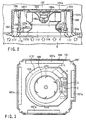
- FIG. 1 is a perspective drawing that shows the disassembled ceiling cassette type air conditioner related to the first embodiment of the present invention
- FIG. 2 is a cross section drawing showing the assembled and operating ceiling cassette type air conditioner.
- 101 stands for an enclosure, and this enclosure 101 is a rectangle in the plan view, the top piece 101a is made into an octagonal shape with the four corners missing, and the side walls 101b are made by integrating a side wall along each side of the top plate 101a.
- the enclosure 101 is hung and fixed from the loft 102 buy a suitable means, and the bottom opening portion is made to face the opening portion 103a made in the ceiling panel.
- the respective inner surfaces of the top plate 101a and a part of the side walls 101b have thermal insulating materials 104 closely attached to them.
- a fan motor 105m that composes the blower 105 is mounted and fixed.
- the axial direction of this fan motor 105m is set in the vertical direction, and to the revolving shaft 105a protruding downwards, the fan 105f is fitted.
- the aforementioned fan 105f is driven and revolved by the fan motor 105m, it will suck in air from the bottom side in the axial direction, and conduct blower action by blowing air out in the circumferential direction.
- heat exchangers 106 are arranged. These heat exchangers 106 are connected with piping to the outdoor unit (not illustrated) such as the outdoor compressor and outdoor heat exchangers that are arranged to compose a refrigerating cycle.
- the aforementioned heat exchangers are rectangular shaped in the plan view, and are located in a position where they receive the air blown from the blower fan 105.
- the heat exchangers 106 are placed on the receiving portion of the drain pan that is engaged to the bottom opening portion of the enclosure 101 via thermal insulating material 104, and they are supported between this drain pan 107 and the enclosure top plate 101a via thermal insulating materials 104.
- the top surface of the heat exchangers 106 is in close contact with the enclosure top plate 101a via thermal insulating material
- the bottom surface of the heat exchanger 106 is in close contact with the drain pan 107.
- the drain pan 107 has each side concavely formed, and gaps exist between the enclosure side walls 101b. Practically, only the corner portions 107b are engaged with the corner portions of the enclosure side-walls 101b via thermal insulating materials 104. Because of this, the air that has passed through the heat exchangers 106 is guided to the concavely formed portions 107a of the drain pan 107.
- the drain pan 107 is bent and formed into an approximately U-shaped cross-section at the same height as the upper edges of the concavely formed portion 107a and the corner portion 107b, and at the bottom portion the aforementioned heat exchangers 106 are arranged.
- a plate portion 107c is made for the whole circumference of the inside bent-upper edge, and at the center of the plate portion 107c, a round opening portion 108 is made with the specified diameter.
- a supporting panel 109 having identical shape dimensions as the plate portion is engaged, and fixed in place by a suitable means.
- an opening portion 110 having identical dimensions as the opening portion 108 made in the plate portion 107c is provided.
- the electrical parts box 111 mentioned later on is mounted to this side portion.
- the top opening portion 112a of the bell-mouth 112 is arranged so as to face it. This bell-mouth 112 will also be described later on.
- the bottom opening portion of the enclosure 101 is blocked by a decorative panel 115 that has a rectangular shape in the plan view.
- This decorative panel 115 is in a position to be exposed from the ceiling panel 103 in the room R to be air-conditioned, and in the center, a rectangular suction inlet 116 is made, and in the peripheral portion, a plurality of narrow rectangular shaped blowing outlets 117 is opened.
- the suction inlet 116 of the decorative panel 115 is mounted so that it faces lower opening portion 112b of the bell-mouth 112.
- the room air sucked in from the suction inlet 116 is led to the bottom opening portion 112b of the bell-mouth 112 as primary side air.
- it is guided by the bell-mouth 112, and from the upper opening portion 112 it is guided to the blower fan 105f.
- each blowing outlet 117 is facing the concavely formed portion of the drain pan 107a, and the air that passes through the heat exchanger 106 is led to the blower outlet 117 via the concavely formed portion 107a, and from here it is guided so that it is blown into the room R to be air-conditioned.
- the electrical parts box 111 is mounted to the supporting panel 109 provided to the outer side of the bell-mouth 112. Thus, it will be arranged on the side where the secondary air of the bell-mouth passes.
- FIG. 3 shows the assembled ceiling cassette type air conditioner, and in addition, it shows the inside state of an enclosure 101 when looked up from the bottom (i.e. when seen from the room side) after the aforementioned decorative panel 115 is removed.
- a part of the blower fan 105 can be seen, and in its periphery, the bell-mouth 112 can be seen.
- the drain pan 107 in the periphery of the bell-mouth 112, there is the drain pan 107, and at the four sides, the concavely formed portions 107a that become the passage of the blowing air can be seen.
- the whole periphery of the drain pan 107 is surrounded by the thermal insulation material 104 and the enclosure 101.
- a pair of electrical parts boxes 111 shown by broken lines are shielded by the bell-mouth 112, and actually they cannot be seen.
- the electrical parts boxes 111 have a rectangular shaped plan view, and at mutually adjacent positions, they are arranged so that they maintain a specified angle versus the shaft center of the bell-mouth 112.
- FIG. 4A shows a cross-section drawing of the electrical parts E that are mounted to the control board S and the electrical parts box 111 that accommodates these control boards and electrical parts E
- FIG. 4B shows the plan view of the mounting positions for the electrical parts E versus the control board S.
- the bottom side opening portion 111b As an electrical parts box 111, against the horizontal top plate 111a, the bottom side opening portion 111b is formed, and in addition, the height dimension of the side walls 111c on one side is made small, and the height dimension of the side walls of opposing side 111d is made to be larger.
- the control board S is formed so that the width will be slightly narrower than the distance between the side walls 111c and 111d of the electrical parts box 111, and a very narrow gap exists between the electrical parts box top plate 111a, and they are suspended by the fixtures 120 so that they will be parallel.
- one of the characteristics is the mounting structure of the electrical parts E versus the electrical parts box 111.
- the electrical parts group Ea having the lowest height dimension is mounted near the side of the side-walls having smaller height dimensions of the electrical parts box 111.
- electrical parts groups Ec are mounted in the order of the height dimensions in the direction of the side-walls 111d that has a large height dimension.
- the electrical parts E are classified into three groups, namely, electrical parts group Ea having the lowest height dimensions, electrical parts group Eb having medium height dimensions, and electrical parts group having the highest height dimension. These parts are arranged in the order of the height on the control board from one end of the short side-wall side to the other side.
- Ea it includes such parts as integrated circuits, resisters, and FET.
- Eb it includes parts such as switching transformer, small capacity condensers, and noise filters.
- Ec it includes large capacity condensers and noise filters.
- control board S to which electrical parts E are mounted are accommodated into the electrical parts box 111, but as mentioned above, to the side-wall side of the electrical parts box 111 having small height dimension 111c, the electrical parts group Ea having the lowest height is made to face them, and to the electrical parts box 111 having the highest side-wall 111d, the electrical parts group Ec having the highest height is made to face them when accommodated.
- the side-wall 111c of the electrical parts box 111 having small height dimension is arranged to face near the peripheral of the straight portion 112c of the bell-mouth 112, and the side-wall 111d of the electrical parts box having large height dimension is arranged to protrude outwards from the peripheral portion 112d formed along the periphery of the bottom opening portion 112b of the bell-mouth.
- the electrical parts group Ea having small height dimension is located on the side of straight portion 112c of the bell-mouth 112, and the electrical parts group Ec having large height dimension will protrude from the peripheral portion 112d of the bell-mouth, and the changes in height dimensions almost perfectly coincide with the tapered shape of the bell-mouth 112.
- the bottom opening portion 111b of the electrical parts box 111 is closed by the covering plate 130, and made into a closed structure.
- the cross-section shape of the covering plate is almost the same as the taper shape of the bell-mouth 112.
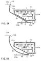
- FIG. 5B shows the case in which the bell mouth cross-section has a top opening portion 112A side that is contracted into a small diameter, then curved to the bottom opening portion 112b side.
- the existence of electrical parts box 111, the fact that the control board S and the electrical parts E are accommodated in it, and the mounting structure of the electrical parts E versus the electrical parts box 111 are exactly the same as the explanation made for FIG. 5A. Therefore, the changes in the height dimension of the electrical parts E is almost the same as the cross-section shape of the bell-mouth 112.
- this is a ceiling cassette type air conditioner that arranges electrical parts box 111 accommodating electrical parts E against bell-mouth 112 and 112A, and by starting the refrigerating cycle operation in the heat exchanger 106 and driving the blower 105, the air of the room R to be air-conditioned will be sucked in from the suction inlet 116 of the decorative panel 115, then guided by the bell-mouth 112 to the blower 105 then blown to the heat exchanger 106.
- the drain pan 107 receives the drain that is generated at the time of heat exchange action in the heat exchanger 106, and after collecting the drain once, it is drained outdoors via a drain hose. Even if either bell-mouth 112 or 112A explained in FIGS. 5A and 5B is used, an ideal cross-section for the bell-mouth can be obtained regardless of the arranging of electrical parts box 111. Therefore, the physical interference of the electrical parts box 111 no longer exists.
- FIGS. 6A - 6C This may also take structures shown in FIGS. 6A - 6C.
- bell-mouth 112B shown in FIG. 6A at least one part of the peripheral portion 112d formed along the periphery of the bottom opening portion 112b is made to protrude slightly towards the outside in comparison with the large height dimension side-wall 111d of the electrical parts box 111, and is bent upwards.
- the bell-mouth 112C shown in FIG. 6B has a curved cross-section shape from the top opening portion 112a to the bottom opening portion 112b, and at least one part of the peripheral portion for the bottom opening portion is made to protrude slightly towards the outside in comparison with the large height dimension side-wall 111d of the electrical parts box 111, and is bent upwards.
- the bell-mouth 112D shown in FIG. 6C has a cross-section shape that is almost straight from the top opening portion 112a to the bottom opening portion 112b, and near the bottom opening portion the diameter is enlarged. After peripheral portion 112e formed along the bottom opening portion 112b secures sufficient width dimension, at least one part is extended to approximately the same length as the side-wall 111d of the electrical parts box 111.
- any one of the bell-mouths 112B, 112C, and 112D is basically set to excellent cross-sectional shape, and this is the same as explained earlier.
- the cross-sectional shapes of the electrical parts box 111 shown in FIGS. 6A and 6B are the same as those explained earlier in FIGS. 5A and 5B.
- the cross-sectional shape of the electrical parts box 111 shown in FIG. 6C has the same height for the whole periphery by matching the cross-sectional shape of the bell-mouth 112D.
- the mounting structure of electrical parts E accommodated in the electrical parts box 111 and 111A is as earlier explained in FIGS. 4A and 4B, and the relative positions that are taken with bell-mouths 112B, 112C, and 112D remain the same.
- bell-mouths 112B, 112C, and 112D it is characteristic that flame retardant synthetic resins or metals be selected, and furthermore, the edge of the bottom opening portion 111b of the electrical parts box 111, 111A are placed in close contact with the outer surface of the bell-mouths 112B, 112C, and 112D and the bottom opening portion of the box is closed.
- the blower characteristics of the bell-mouths 112B, 112C, and 112D are improved, and at the same time, since the aforementioned bell-mouths also act as the covering plate, the number of parts can be reduced. As a result, the height of the enclosure can be reduced that much and the unit can be made more compact.
- bell-mouth 112B, 112C, and 112D even if specific electrical parts generate extremely large heat, the bell-mouth will not receive such thermal influence, and even if there is no covering plate accident prevention such as heat deformation is possible.
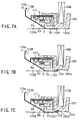
- Bell-mouth structure shown in FIGS. 7A - 7C may also be used.
- Bell-mouth 112E shown by FIG. 7A elongates the periphery portion 112f formed along the periphery of the bottom opening portion 112b more outwards than the electrical parts box 111 and makes the extended portion, and the top surface of this extended portion 112f comes into close contact with the bottom portion 107d of the drain pan 107.
- Bell-mouth 112F shown in FIG. 7B has the edge of the extended portion 112f bent upwards to form a rib 113, and the gap between the bottom surface 107d of the drain pan 107 that comes into contact with the tip of the rib 113 is made minus.
- Bell-mouth 112G shown in FIG. 7C has a seal member 114 attached to the end of the extended portion 112f, and this seal member 114 is engaged with the concave portion 107e made at the bottom portion of the drain pan 107d.
- the bell-mouth 112F shown in FIG. 7B has the rib 113 integrated to the edge of the extended portion 112f, the dimensional accuracy and the mechanical strength of the bell-mouth periphery have been improved, and by making minus contact with the bottom portion 107d of the drain pan, a pressing force generates in the bell-mouth and the shielding function of primary air and secondary air improves all the more, and the minute gaps formed at the time of assembly are absorbed, and the blower characteristics are further stabilized.
- FIGS. 8A and 8B Bell-mouth structures shown in FIGS. 8A and 8B may also be taken.
- the electrical parts E accommodated in the electrical parts box 111 were omitted, but the same mounting explained previously was conducted. Therefore, similar effects can be obtained.
- Bell-mouth 112H shown in FIG. 8A is based on the assumption that the periphery of the bottom opening portion 112b has an extension portion 112f that extends towards the outside beyond the large height dimension sidewall 111d of the electrical parts box 111, and characterized by having an integrated hooking portion 140 that is formed by bending the edge upwards at a specified position of the extended portion 112f.
- the decorative panel 115 can be freely mounted to or removed from the enclosure 101, and it is mounted with fixtures that are not illustrated.
- the decorative panel 115 is equipped with a suspension device for making temporary mounting, and by hooking this to the specified position, the decorative panel 115 can be temporarily attached, then by using fixtures it can be fixed firmly.
- the temporary suspension device 145 of the decorative panel 115 is hooked and the decorative panel is mounted temporarily, then fixed firmly with fixtures
- the hooking portion 140 that is made by bending the extension portion 112f of the bell-mouth 112H is positioned.
- the depth dimension of the concave portion 107f of the drain pan 107 must be formed deep so that no troubles arise during the mounting and demounting work of the temporary suspension device 145 of the decorative panel 115 against the hooking portion 140.
- the edge of the extension portion 112g provided for the bell-mouth 112J is more outwards than the large height dimension sidewall 111d of the electrical parts box 111, and in addition, it is set so that it will be inside of the heat exchanger receiving portion of the drain pan 107.
- the hooking portion 140 provided at the edge of the extension portion 112g is located between the electrical parts box 111 and the drain pan 107, and the temporary suspension device 145 of the decorative panel is hooked to this.
- the concave portion 107 shown in FIG. 8A need not be formed, and the heat exchanger 106 supporting position of the drain pan 107 can be lowered that much.
- the top surface position of the aforementioned heat exchanger 106 will be lowered by dimension h, and the height dimension from the bottom portion 107 of the drain pan to the top surface of the heat exchanger 106 in FIG. 8A was La but in the case of FIG. 8B, Lb will suffice.
- the height dimension of the enclosure 101 can be made that much smaller, and the further miniaturization of the unit can be promoted.
- FIG. 9 is a perspective drawing that shows a disassembled ceiling cassette type air conditioner
- FIG. 10 is a cross-section view that shows an assembled and operating ceiling cassette type air conditioner.
- 1 stands for the enclosure, and this enclosure 1 is a rectangle when seen by the plan view, but the four corners are missing and an octagonal shaped top plate 1a is formed. Along each side of this top portion 1a an integrated side-wall 1b is made, and the bottom of the enclosure 1 is left open.
- the aforementioned enclosure 1 In the case of the aforementioned enclosure 1, it is supported and fixed to the ceiling by a suitable means, and the bottom opening portion is made to face the opening 3a made in the ceiling panel 3. In the inner surface of the top portion 1a and the side-walls 1b, insulating materials are closely attached.
- fan motor 5m On the inner center portion of the enclosure top portion, fan motor 5m that compose the blower is mounted and fixed.
- the axial direction of this fan motor 5m is facing the vertical direction, and to the revolving shaft protruding downwards, the fan 5f is engaged.
- the aforementioned fan 5f is driven and revolved by the fan motor 5m, from the lower side of the axial direction air will be sucked in, and blower action that blows air in the circumferential direction will be conducted.
- heat exchangers 6 are arranged so as to surround it, and they are connected with piping that compose refrigerating cycle with compressors and outdoor heat exchangers arranged to the outdoor units which are not shown.
- the above heat exchanger 6 is approximately a rectangle according to the plan view, and it is located in a position where it will receive the air blown by blower fan 5.
- the heat exchanger 6 is placed on the drain pan 7 that is fitted to the lower opening portion of the enclosure 1 via thermal insulating material 4, and the heat exchanger is supported via thermal insulating material 4 placed between the drain pan 7 and the enclosure top portion 1a.
- the top surface of the heat exchanger 6 is in close contact with the enclosure top plate 1a via thermal insulating materials 4, and the lower side of the heat exchanger 6 is in close contact with the drain pan.
- the drain pan 7 is designed so that each side portion 7a is formed concavely, and a space exists between it and the enclosure side-wall 1b. Thus, practically, only the corner portion 7b is engaged with the corner portion of the enclosure side-wall 1b via the thermal insulation material 4. Based on this fact, the air that has passed through the heat exchanger 6 is led to the concavely formed portion 7a of the drain pan 7.
- the drain pan 7 is formed by bending it so that the cross section will be approximately U-shaped at an identical height as the upper edge of the concavely formed portion 7a and corner portion 7b, and at the bottom portion, the aforementioned heat-exchanger 6 is arranged.
- a plate portion 7c is installed for the whole periphery, and at the center of the plate portion a round opening 8 having the specified diameter is placed.
- a supporting panel 9 having identical dimensions is engaged, and they are fixed in place by a suitable means.
- an opening portion having the same dimensions as the opening portion 8 made in the plate portion 7c of the supporting panel 9 is provided, and to this side portion position, the controller 11 and other electrical parts E are mounted.
- the upper opening portion 12a of the bell-mouth 12 is arranged to face a position close to the shaft center of fan 5f of the aforementioned blower 5.
- the lower opening portion 12b of the bell-mouth 12 possesses a portion bent horizontally along the periphery of the opening, and is in close contact with the bottom surface of the drain pan 7.
- the diameter of the upper opening portion 12a of the bell-mouth 12 is small, and the diameter of the bottom opening portion 12b is large, and a bell-mouth 12 as a whole will have a tapered cross-section.
- a very small diameter through-hole 13 is made, and as referred to later on, a temperature sensor is inserted through it and supported.
- the bottom opening portion of enclosure 1 is blocked by the decorative panel 15 which appears as a rectangle in the plan view.
- This decorative panel 15 is located in the ceiling panel 3 at a position where it will be exposed to the inside of the room R to be air-conditioned.
- a rectangle shaped suction inlet 16 is provided, and around this, a plurality of narrow rectangular blowing outlets 17 is opened.
- the suction inlet 16 of the decorative panel 15 is installed so that it will face the bottom opening portion 12b of the bell-mouth 12.
- the room air sucked in from the suction inlet 16 is led to the bottom opening portion 12b of the bell-mouth 12, and in addition, the air is guided by the bell-mouth 12, and from its upper opening portion 12a, the air is led to the blower fan 5f.
- each blowing outlet 17 is facing the concavely formed portion 7a of the drain pan 7, and the air that passes through the heat exchanger 6 is led to the blowing outlet 17 via the concavely formed portion 7a, and from the blowing outlet the air is guided so that it will blow out to the room R to be air conditioned.
Abstract
Description
- The present invention is concerned with ceiling cassette type air conditioner mounted to the ceiling of the room to be air conditioned, and in particular, it relates to the improvement of the mounting of temperature sensor that detects the temperature of the room air which is sucked in and guided by the bell-mouth, and the improvement of the arrangement of electrical parts box versus the bell-mouth as well as the mounting structure of the electrical parts in the electrical parts box.
- The ceiling cassette type air conditioner comprises an enclosure which is open at the bottom, a blower located at approximately the center of this enclosure, heat exchangers arranged around the blower, a bell-mouth that is installed so that its upper opening portion is facing the axial direction of the blower, and a decorative panel exposed to the room to be air conditioned from the ceiling surface, and which possesses a suction inlet facing the bottom opening portion of the bell-mouth, and which possesses blower outlets around the suction inlet, and blocks the lower opening portion of the enclosure.
- Therefore, only the decorative panel that possesses the suction inlet and the blower outlet is exposed from the ceiling panels, that is, the enclosures of the ceiling cassette type air conditioners are embedded above the ceiling panels of the room to be air conditioned, and the inhabitants do not receive the sense of oppression at all, so there is a tendency of their usage increasing.
- In such an air conditioner is equipped with electrical parts that control motor-driven parts such as a blower, and electrical parts that receive detection signals such as remote controller (remote control operating panel) as well as operation instruction signals transmitted from various detection means, and change them into control signals.
- The electrical parts consist of many electric parts and electronic parts, and because of the limited space in the enclosure, the electric parts are attached to a single control board, and after making electrical connections, they are accommodated in an electrical parts box.
- Furthermore, inside of the enclosure, heat exchangers, a drain pan to receive the drain water generated from the heat exchangers, a blower to blow the room air through the heat exchangers, and a bell mouth to guide the room air smoothly to the blower are arranged.
- Such a ceiling cassette type air conditioner is described for example in UK patent application GB 2314924.
- Hitherto, there were problems related to arrangement of electrical parts box against the aforementioned bell-mouth and mounting structure of the electrical parts that are accommodated in the electrical parts box.
- In other words, as electrical parts accommodated in the electrical parts box, there are all kinds of parts, for instance, small-sized electronic parts such as integrated circuits, resistances, and FET, a rather big-sized large capacity condenser, and medium-sized parts such as switching transformer, small capacity condenser, noise filter, etc. All of these parts are mounted to a single board for the convenience of circuit designing. As a result, the total height dimension of the electrical parts box uses the control board as the basis, and for instance, the big-sized electrical parts such as the large capacity condenser, are accommodated with dimensions having allowance. As a result, the electrical parts-box becomes big-sized, and it hinders the miniaturization of the unit.
- In addition, for instance, as shown in FIG. 11A, the bell-mouth Ba originally has a tapered shape (cone-shaped) cross section, that is, small diameter at the top opening, and large diameter at the bottom opening, but in order to mount the electrical parts box D, a part of the tapered surface is bent back to the upper side, then bent horizontally. The electrical parts box D is mounted to the passage side of the primary air (air which is sucked in) at the lower portion of the bell-mouth horizontal plane. In the drawing S stands for the control board and E stands for the electrical parts mounted to the control board S.
- On the other hand, as shown in FIG. 11B, bell-mouth Bb has a part of the tapered portion bent down vertically, then bent horizontally. The electrical parts box D is mounted above the horizontal plane of the bell-mouth on the passage side of the secondary air.
- In this way, whether it is bell-mouth Ba or Bb, in order to mount the electrical parts box D, a part of the bell-mouth has to be deformed, and consequently, the bell-mouth does not take an ideal form, thereby hindering the blower performance.
- On the other hand, the air conditioner, in order to conduct the pre-set air conditioning, one of the control conditions is to measure the present room temperature. This is possible by detecting the temperature of the air of the room to be air conditioned by a temperature sensor when the air is sucked in and guided by the bell-mouth, and transmitting these detection signals to the controller among the electrical parts.
- As an actual temperature sensor mounting structure, a sensor supporting member is mounted to the inner surface side of the suction air guide side of the bell-mouth, and the sensor is supported by this supporter. The temperature sensor must be electrically connected with a controller which composes one of the electrical parts, but these electrical parts can secure arranging space only above the bell-mouth.
- As a result, a lead wire of which one end is connected to the controller is extended from the upper part of the bell-mouth to the periphery of the sensor, then further stretched to the inner surface side of the bell-mouth. Furthermore, the other end must be connected to the temperature sensor that is supported by the sensor-supporting member. In conclusion, the total length of the lead wire becomes very long, and it has bad influence on the cost.
- Not only the cost, but also at the time of maintenance when it becomes necessary to remove the bell-mouth, the sensor supporting member will have to be removed from the bell-mouth together with the temperature sensor. Furthermore, after the maintenance work is completed, the lead wire will have to be extended and connection will have to be made. Thus, there were problems such as being time-consuming, and having bad maintenance operation efficiency.
- The first objective of the present invention is to obtain a bell-mouth shape having excellent blower characteristics, and to mount the electrical parts into the electrical parts box without interfering with the shape of the bell-mouth, thereby providing a ceiling cassette type air conditioner which can be designed compactly.
- The present invention comprises a housing provided on the ceiling panel of a room and having a bottom opening, a heat exchanger arranged in the housing; a drain pan provided in the housing, a blower provided in the housing, a bell-mouth provided in the housing and having a bottom opening and an outer circumferential surface, an electrical part box provided in the housing and accommodating electrical part; and a decorative panel closing the bottom opening of the housing, having an inlet port opposing the bottom opening of the bell-mouth and having outlet ports surrounding the inlet port, wherein the electrical part box is arranged near that side of the bell-mouth at which secondary air flows, the electrical parts are mounted on a control board provided in the electrical part box, and those of the electrical parts which are located near the outer circumferential surface of the bell-mouth are less tall than the other electrical parts.
- According to the present invention, it is possible to set the bell-mouth in a shape having excellent blowing characteristics, and without interfering such bell-mouth shape, the electrical parts inside of the electrical parts box are mounted, and this has an effect of making the unit compact.
- Additional objects and advantages of the invention will be set forth in the description which follows, and in part will be obvious from the description, or may be learned by practice of the invention. The objects and advantages of the invention may be realized and obtained by means of the instrumentalities and combinations particularly pointed out hereinafter.
- The accompanying drawings, which are incorporated in and constitute a part of the specification, illustrate presently preferred embodiments of the invention, and together with the general description given above and the detailed description of the preferred embodiments given below, serve to explain the principles of the invention.
- FIG. 1 is related to the first embodiment of the present invention and it shows a perspective drawing of the same ceiling cassette air conditioner in a disassembled state.
- FIG. 2 is a cross-section of the same ceiling cassette type air conditioner.
- FIG. 3 is a bottom view of the same ceiling cassette air conditioner in a state in which the decorative panel is removed.
- FIG. 4A is a cross-section view of the electrical parts box that accommodates the electrical parts mounted to the control board built into the same ceiling cassette type air conditioner.
- FIG. 4B is a plan view of control board that mounts the electrical parts built into the same ceiling cassette type air conditioner.
- FIGS. 5A and 5B are cross-section views that explain the relative relation between the bell mouth and the electrical parts box which are built into the same ceiling cassette type air conditioner, and which have mutually different shapes.
- FIGS. 6A - 6C are cross-section drawings that explain the relative relation between the bell-mouth and the electrical parts box which are built into the same ceiling cassette type air conditioner, and which have mutually different cross-sectional shapes.
- FIGS. 7A - 7C are cross-section drawings that explain the relative relations among the bell-mouth, the electrical parts box, and the drain pan which are built into the same ceiling cassette type air conditioner
- FIGS. 8A and 8B are cross-section drawings that explain the relative relations among the bell-mouth, the electrical parts box, and the drain pan which are built into the same ceiling cassette type air conditioner
- FIG. 9 is a perspective view of a disassembled ceiling cassette type air conditioner related to the second embodiment of the present invention is shown.
- FIG. 10 is a cross-section view of the same ceiling cassette type air conditioner is shown.
- FIGS. 11A and 11B are cross-section drawings that explain the relative relation between the conventional bell-mouth and the electrical parts box which have mutually different cross-sectional shapes.
-
- The embodiments of the invention will be described with reference to the accompanying drawings.
- FIG. 1 is a perspective drawing that shows the disassembled ceiling cassette type air conditioner related to the first embodiment of the present invention, and FIG. 2 is a cross section drawing showing the assembled and operating ceiling cassette type air conditioner.
- In the drawing, 101 stands for an enclosure, and this
enclosure 101 is a rectangle in the plan view, thetop piece 101a is made into an octagonal shape with the four corners missing, and theside walls 101b are made by integrating a side wall along each side of thetop plate 101a. - The
enclosure 101 is hung and fixed from theloft 102 buy a suitable means, and the bottom opening portion is made to face the opening portion 103a made in the ceiling panel. The respective inner surfaces of thetop plate 101a and a part of theside walls 101b have thermalinsulating materials 104 closely attached to them. - To the center portion inner surface of the
enclosure top plate 101a, afan motor 105m that composes theblower 105 is mounted and fixed. The axial direction of thisfan motor 105m is set in the vertical direction, and to the revolvingshaft 105a protruding downwards, thefan 105f is fitted. When theaforementioned fan 105f is driven and revolved by thefan motor 105m, it will suck in air from the bottom side in the axial direction, and conduct blower action by blowing air out in the circumferential direction. In addition, centered around theblower 105,heat exchangers 106 are arranged. Theseheat exchangers 106 are connected with piping to the outdoor unit (not illustrated) such as the outdoor compressor and outdoor heat exchangers that are arranged to compose a refrigerating cycle. - The aforementioned heat exchangers are rectangular shaped in the plan view, and are located in a position where they receive the air blown from the
blower fan 105. Theheat exchangers 106 are placed on the receiving portion of the drain pan that is engaged to the bottom opening portion of theenclosure 101 via thermal insulatingmaterial 104, and they are supported between thisdrain pan 107 and theenclosure top plate 101a via thermal insulatingmaterials 104. In other words, the top surface of theheat exchangers 106 is in close contact with theenclosure top plate 101a via thermal insulating material, and the bottom surface of theheat exchanger 106 is in close contact with thedrain pan 107. - The
drain pan 107 has each side concavely formed, and gaps exist between theenclosure side walls 101b. Practically, only thecorner portions 107b are engaged with the corner portions of the enclosure side-walls 101b via thermal insulatingmaterials 104. Because of this, the air that has passed through theheat exchangers 106 is guided to the concavely formedportions 107a of thedrain pan 107. - Furthermore, the
drain pan 107 is bent and formed into an approximately U-shaped cross-section at the same height as the upper edges of the concavely formedportion 107a and thecorner portion 107b, and at the bottom portion theaforementioned heat exchangers 106 are arranged. Aplate portion 107c is made for the whole circumference of the inside bent-upper edge, and at the center of theplate portion 107c, a round opening portion 108 is made with the specified diameter. To theplate portion 107c that composes thedrain pan 107, a supportingpanel 109 having identical shape dimensions as the plate portion is engaged, and fixed in place by a suitable means. In the center of the supportingpanel 109, anopening portion 110 having identical dimensions as the opening portion 108 made in theplate portion 107c is provided. In addition, the electrical parts box 111 mentioned later on is mounted to this side portion. - Via such opening portion 108 of
plate portion 107c andopening portion 110 of the supportingpanel 109, in a very close position to thefan 105f of theblower 105, thetop opening portion 112a of the bell-mouth 112 is arranged so as to face it. This bell-mouth 112 will also be described later on. - The bottom opening portion of the
enclosure 101 is blocked by adecorative panel 115 that has a rectangular shape in the plan view. Thisdecorative panel 115 is in a position to be exposed from theceiling panel 103 in the room R to be air-conditioned, and in the center, arectangular suction inlet 116 is made, and in the peripheral portion, a plurality of narrow rectangular shaped blowingoutlets 117 is opened. - Furthermore, if further explanation is given, the
suction inlet 116 of thedecorative panel 115 is mounted so that it faceslower opening portion 112b of the bell-mouth 112. Thus, by the action of theblower 105, the room air sucked in from thesuction inlet 116 is led to thebottom opening portion 112b of the bell-mouth 112 as primary side air. In addition, it is guided by the bell-mouth 112, and from theupper opening portion 112 it is guided to theblower fan 105f. - On the other hand, each blowing
outlet 117 is facing the concavely formed portion of thedrain pan 107a, and the air that passes through theheat exchanger 106 is led to theblower outlet 117 via the concavely formedportion 107a, and from here it is guided so that it is blown into the room R to be air-conditioned. - Furthermore, the
electrical parts box 111 is mounted to the supportingpanel 109 provided to the outer side of the bell-mouth 112. Thus, it will be arranged on the side where the secondary air of the bell-mouth passes. - FIG. 3 shows the assembled ceiling cassette type air conditioner, and in addition, it shows the inside state of an
enclosure 101 when looked up from the bottom (i.e. when seen from the room side) after the aforementioneddecorative panel 115 is removed. At the center portion, a part of theblower fan 105 can be seen, and in its periphery, the bell-mouth 112 can be seen. Furthermore, in the periphery of the bell-mouth 112, there is thedrain pan 107, and at the four sides, the concavely formedportions 107a that become the passage of the blowing air can be seen. The whole periphery of thedrain pan 107 is surrounded by thethermal insulation material 104 and theenclosure 101. - A pair of
electrical parts boxes 111 shown by broken lines are shielded by the bell-mouth 112, and actually they cannot be seen. Theelectrical parts boxes 111 have a rectangular shaped plan view, and at mutually adjacent positions, they are arranged so that they maintain a specified angle versus the shaft center of the bell-mouth 112. - FIG. 4A shows a cross-section drawing of the electrical parts E that are mounted to the control board S and the electrical parts box 111 that accommodates these control boards and electrical parts E, and FIG. 4B shows the plan view of the mounting positions for the electrical parts E versus the control board S.
- As an
electrical parts box 111, against the horizontaltop plate 111a, the bottomside opening portion 111b is formed, and in addition, the height dimension of theside walls 111c on one side is made small, and the height dimension of the side walls of opposingside 111d is made to be larger. - The control board S is formed so that the width will be slightly narrower than the distance between the
side walls electrical parts box 111, and a very narrow gap exists between the electrical parts boxtop plate 111a, and they are suspended by thefixtures 120 so that they will be parallel. - In the present invention, one of the characteristics is the mounting structure of the electrical parts E versus the
electrical parts box 111. In other words, near the side of the side-walls having smaller height dimensions of theelectrical parts box 111, the electrical parts group Ea having the lowest height dimension is mounted. Then electrical parts groups Ec are mounted in the order of the height dimensions in the direction of the side-walls 111d that has a large height dimension. - Concretely speaking, the electrical parts E are classified into three groups, namely, electrical parts group Ea having the lowest height dimensions, electrical parts group Eb having medium height dimensions, and electrical parts group having the highest height dimension. These parts are arranged in the order of the height on the control board from one end of the short side-wall side to the other side.
- If we express the group of electrical parts with the lowest height as Ea, it includes such parts as integrated circuits, resisters, and FET. If we express the group of electrical parts with the medium height as Eb, it includes parts such as switching transformer, small capacity condensers, and noise filters. If we express the group of electrical parts with the highest height as Ec, it includes large capacity condensers and noise filters.
- In this way, control board S to which electrical parts E are mounted are accommodated into the
electrical parts box 111, but as mentioned above, to the side-wall side of the electrical parts box 111 havingsmall height dimension 111c, the electrical parts group Ea having the lowest height is made to face them, and to the electrical parts box 111 having the highest side-wall 111d, the electrical parts group Ec having the highest height is made to face them when accommodated. - In FIG. 5A and after, position setting of the electrical parts box versus the bell-
mouth 112 and the mounting structure of the electrical parts are described concretely. In other words, in FIG. 5A from theupper opening portion 112a to a specified distance downwards, it is designed straight, and below thisstraight portion 112c to thebottom opening portion 112b, it is designed with a taper (This is also referred to as conical-shaped or bell rim shape of a bugle), and the case in whichbell mouth 112 is adopted is shown. - If we repeat our description, in case the room air suction-guide side of bell-
mouth 112 is referred to as the primary side, and the blowing side is referred to as the secondary side, since theelectrical parts box 111 is located at the upper side of the bell-mouth 112, it will be arranged on the secondary air passage side. - The side-
wall 111c of the electrical parts box 111 having small height dimension is arranged to face near the peripheral of thestraight portion 112c of the bell-mouth 112, and the side-wall 111d of the electrical parts box having large height dimension is arranged to protrude outwards from theperipheral portion 112d formed along the periphery of thebottom opening portion 112b of the bell-mouth. - Because of the above, in the case of the electrical parts E that is mounted to the control board and accommodated inside of the
electrical parts box 111, the electrical parts group Ea having small height dimension is located on the side ofstraight portion 112c of the bell-mouth 112, and the electrical parts group Ec having large height dimension will protrude from theperipheral portion 112d of the bell-mouth, and the changes in height dimensions almost perfectly coincide with the tapered shape of the bell-mouth 112. - The
bottom opening portion 111b of theelectrical parts box 111 is closed by the coveringplate 130, and made into a closed structure. In other words, the cross-section shape of the covering plate is almost the same as the taper shape of the bell-mouth 112. - By the existence of the above mentioned covering plate, entrance of dust and water droplets into the electrical parts box 111 can be completely obstructed on one hand, and on the other hand, bad influence of the heat received by the bell-mouth by the heat dissipation of the electrical parts E can be prevented.
- FIG. 5B shows the case in which the bell mouth cross-section has a
top opening portion 112A side that is contracted into a small diameter, then curved to thebottom opening portion 112b side. The existence ofelectrical parts box 111, the fact that the control board S and the electrical parts E are accommodated in it, and the mounting structure of the electrical parts E versus theelectrical parts box 111 are exactly the same as the explanation made for FIG. 5A. Therefore, the changes in the height dimension of the electrical parts E is almost the same as the cross-section shape of the bell-mouth 112. - In the above manner, this is a ceiling cassette type air conditioner that arranges electrical parts box 111 accommodating electrical parts E against bell-
mouth heat exchanger 106 and driving theblower 105, the air of the room R to be air-conditioned will be sucked in from thesuction inlet 116 of thedecorative panel 115, then guided by the bell-mouth 112 to theblower 105 then blown to theheat exchanger 106. - At the time the air passes through the
heat exchanger 106, heat exchange is conducted, and subsequently, via the concavely formedportion 107a of thedrain pan 107, the air reaches theblowing outlet 117, and further blown to the room R and conducts air-conditioning. Thedrain pan 107 receives the drain that is generated at the time of heat exchange action in theheat exchanger 106, and after collecting the drain once, it is drained outdoors via a drain hose. Even if either bell-mouth electrical parts box 111. Therefore, the physical interference of the electrical parts box 111 no longer exists. Since there is no air passage resistance, a bell-mouth shape having excellent blower characteristics can be set, and furthermore, improvement in air-conditioning capacity can be aimed at. In addition, electrical parts E can be mounted without interfering with the shape of the bell-mouth, and it means that the height dimension of theenclosure 101 can be reduced and the air-conditioning unit itself can be made more compact. - This may also take structures shown in FIGS. 6A - 6C. In the case of bell-
mouth 112B shown in FIG. 6A, at least one part of theperipheral portion 112d formed along the periphery of thebottom opening portion 112b is made to protrude slightly towards the outside in comparison with the large height dimension side-wall 111d of theelectrical parts box 111, and is bent upwards. - The bell-
mouth 112C shown in FIG. 6B has a curved cross-section shape from thetop opening portion 112a to thebottom opening portion 112b, and at least one part of the peripheral portion for the bottom opening portion is made to protrude slightly towards the outside in comparison with the large height dimension side-wall 111d of theelectrical parts box 111, and is bent upwards. - The bell-
mouth 112D shown in FIG. 6C has a cross-section shape that is almost straight from thetop opening portion 112a to thebottom opening portion 112b, and near the bottom opening portion the diameter is enlarged. Afterperipheral portion 112e formed along thebottom opening portion 112b secures sufficient width dimension, at least one part is extended to approximately the same length as the side-wall 111d of theelectrical parts box 111. - Although the cross section varies slightly, any one of the bell-
mouths - The cross-sectional shapes of the electrical parts box 111 shown in FIGS. 6A and 6B are the same as those explained earlier in FIGS. 5A and 5B. The cross-sectional shape of the electrical parts box 111 shown in FIG. 6C has the same height for the whole periphery by matching the cross-sectional shape of the bell-
mouth 112D. - In any case, the mounting structure of electrical parts E accommodated in the
electrical parts box mouths - Here, as the material for bell-
mouths bottom opening portion 111b of theelectrical parts box mouths - Therefore, since the mounting structure of the electrical parts E is limited, the blower characteristics of the bell-
mouths - In addition, by selecting the material of bell-
mouth - Bell-mouth structure shown in FIGS. 7A - 7C may also be used. In other words, Bell-
mouth 112E shown by FIG. 7A elongates theperiphery portion 112f formed along the periphery of thebottom opening portion 112b more outwards than theelectrical parts box 111 and makes the extended portion, and the top surface of thisextended portion 112f comes into close contact with thebottom portion 107d of thedrain pan 107. - Bell-
mouth 112F shown in FIG. 7B has the edge of theextended portion 112f bent upwards to form a rib 113, and the gap between thebottom surface 107d of thedrain pan 107 that comes into contact with the tip of the rib 113 is made minus. - Bell-
mouth 112G shown in FIG. 7C has a seal member 114 attached to the end of theextended portion 112f, and this seal member 114 is engaged with the concave portion 107e made at the bottom portion of thedrain pan 107d. - In any case, the mounting structure of the electrical parts E accommodated in the
electrical parts box 111 is as previously explained in FIGS. 4A and 4B, and the relative positions of bell-mouths - In any of the bell-
mouths extended portion 112f was made to come into close contact with thebottom portion 107d of thedrain pan 107, it possesses the function of accurately shielding the primary air and secondary air of the bell-mouth at this contact portion, and even greater improvement in the blower characteristics can be aimed at. - In particular, since the bell-
mouth 112F shown in FIG. 7B has the rib 113 integrated to the edge of theextended portion 112f, the dimensional accuracy and the mechanical strength of the bell-mouth periphery have been improved, and by making minus contact with thebottom portion 107d of the drain pan, a pressing force generates in the bell-mouth and the shielding function of primary air and secondary air improves all the more, and the minute gaps formed at the time of assembly are absorbed, and the blower characteristics are further stabilized. - Bell-mouth structures shown in FIGS. 8A and 8B may also be taken. In these drawings the electrical parts E accommodated in the
electrical parts box 111 were omitted, but the same mounting explained previously was conducted. Therefore, similar effects can be obtained. - Bell-
mouth 112H shown in FIG. 8A is based on the assumption that the periphery of thebottom opening portion 112b has anextension portion 112f that extends towards the outside beyond the largeheight dimension sidewall 111d of theelectrical parts box 111, and characterized by having an integrated hookingportion 140 that is formed by bending the edge upwards at a specified position of theextended portion 112f. On the other hand, thedecorative panel 115 can be freely mounted to or removed from theenclosure 101, and it is mounted with fixtures that are not illustrated. Actually, thedecorative panel 115 is equipped with a suspension device for making temporary mounting, and by hooking this to the specified position, thedecorative panel 115 can be temporarily attached, then by using fixtures it can be fixed firmly. Here, to the hookingportion 140 formed at theextension portion 112f of the bell-mouth 112H, thetemporary suspension device 145 of thedecorative panel 115 is hooked and the decorative panel is mounted temporarily, then fixed firmly with fixtures - Hitherto, an exclusive receiving metal piece corresponding to the hooking
portion 140 was prepared, and at the time of molding thedrain pan 107 the aforementioned metal piece was embedded. Thus, the number of parts increased and the molding was troublesome. By adopting the abovementioned composition, the number of parts can be decreased and the processing trouble can be reduced. - Furthermore, in the composition shown in FIG. 8A, at the
bottom portion 107d of thedrain pan 107, a part of it is concavely formed, and to this concave portion 107f, the hookingportion 140 that is made by bending theextension portion 112f of the bell-mouth 112H is positioned. The depth dimension of the concave portion 107f of thedrain pan 107 must be formed deep so that no troubles arise during the mounting and demounting work of thetemporary suspension device 145 of thedecorative panel 115 against the hookingportion 140. - On the other hand, in the composition shown .in FIG. 8B, the edge of the
extension portion 112g provided for the bell-mouth 112J is more outwards than the largeheight dimension sidewall 111d of theelectrical parts box 111, and in addition, it is set so that it will be inside of the heat exchanger receiving portion of thedrain pan 107. The hookingportion 140 provided at the edge of theextension portion 112g is located between theelectrical parts box 111 and thedrain pan 107, and thetemporary suspension device 145 of the decorative panel is hooked to this. - Therefore, in this case, the
concave portion 107 shown in FIG. 8A need not be formed, and theheat exchanger 106 supporting position of thedrain pan 107 can be lowered that much. - Actually, the top surface position of the
aforementioned heat exchanger 106 will be lowered by dimension h, and the height dimension from thebottom portion 107 of the drain pan to the top surface of theheat exchanger 106 in FIG. 8A was La but in the case of FIG. 8B, Lb will suffice. As a result, the height dimension of theenclosure 101 can be made that much smaller, and the further miniaturization of the unit can be promoted. - FIG. 9 is a perspective drawing that shows a disassembled ceiling cassette type air conditioner, and FIG. 10 is a cross-section view that shows an assembled and operating ceiling cassette type air conditioner.
- In the drawing, 1 stands for the enclosure, and this
enclosure 1 is a rectangle when seen by the plan view, but the four corners are missing and an octagonal shaped top plate 1a is formed. Along each side of this top portion 1a an integrated side-wall 1b is made, and the bottom of theenclosure 1 is left open. - In the case of the
aforementioned enclosure 1, it is supported and fixed to the ceiling by a suitable means, and the bottom opening portion is made to face the opening 3a made in the ceiling panel 3. In the inner surface of the top portion 1a and the side-walls 1b, insulating materials are closely attached. - On the inner center portion of the enclosure top portion,
fan motor 5m that compose the blower is mounted and fixed. The axial direction of thisfan motor 5m is facing the vertical direction, and to the revolving shaft protruding downwards, thefan 5f is engaged. When theaforementioned fan 5f is driven and revolved by thefan motor 5m, from the lower side of the axial direction air will be sucked in, and blower action that blows air in the circumferential direction will be conducted. - Furthermore, with the
blower 5 in the center,heat exchangers 6 are arranged so as to surround it, and they are connected with piping that compose refrigerating cycle with compressors and outdoor heat exchangers arranged to the outdoor units which are not shown. - The
above heat exchanger 6 is approximately a rectangle according to the plan view, and it is located in a position where it will receive the air blown byblower fan 5. Theheat exchanger 6 is placed on thedrain pan 7 that is fitted to the lower opening portion of theenclosure 1 via thermal insulating material 4, and the heat exchanger is supported via thermal insulating material 4 placed between thedrain pan 7 and the enclosure top portion 1a. In other words, the top surface of theheat exchanger 6 is in close contact with the enclosure top plate 1a via thermal insulating materials 4, and the lower side of theheat exchanger 6 is in close contact with the drain pan. - The
drain pan 7 is designed so that eachside portion 7a is formed concavely, and a space exists between it and the enclosure side-wall 1b. Thus, practically, only thecorner portion 7b is engaged with the corner portion of the enclosure side-wall 1b via the thermal insulation material 4. Based on this fact, the air that has passed through theheat exchanger 6 is led to the concavely formedportion 7a of thedrain pan 7. - Furthermore, the
drain pan 7 is formed by bending it so that the cross section will be approximately U-shaped at an identical height as the upper edge of the concavely formedportion 7a andcorner portion 7b, and at the bottom portion, the aforementioned heat-exchanger 6 is arranged. At the inside of the bent upper edge, aplate portion 7c is installed for the whole periphery, and at the center of the plate portion around opening 8 having the specified diameter is placed. - To the
plate portion 7c that composes thedrain pan 7, a supporting panel 9 having identical dimensions is engaged, and they are fixed in place by a suitable means. At the center of the supporting panel 9, an opening portion having the same dimensions as theopening portion 8 made in theplate portion 7c of the supporting panel 9 is provided, and to this side portion position, thecontroller 11 and other electrical parts E are mounted. - Via the opening portions of
such plate portion 7c and supporting panel 9, theupper opening portion 12a of the bell-mouth 12 is arranged to face a position close to the shaft center offan 5f of theaforementioned blower 5. - The
lower opening portion 12b of the bell-mouth 12 possesses a portion bent horizontally along the periphery of the opening, and is in close contact with the bottom surface of thedrain pan 7. - The diameter of the
upper opening portion 12a of the bell-mouth 12 is small, and the diameter of thebottom opening portion 12b is large, and a bell-mouth 12 as a whole will have a tapered cross-section. At one portion of this bell-mouth 12, a very small diameter through-hole 13 is made, and as referred to later on, a temperature sensor is inserted through it and supported. - The bottom opening portion of
enclosure 1 is blocked by thedecorative panel 15 which appears as a rectangle in the plan view. Thisdecorative panel 15 is located in the ceiling panel 3 at a position where it will be exposed to the inside of the room R to be air-conditioned. At the center portion, a rectangle shapedsuction inlet 16 is provided, and around this, a plurality of narrowrectangular blowing outlets 17 is opened. - If further explanation is made, the
suction inlet 16 of thedecorative panel 15 is installed so that it will face thebottom opening portion 12b of the bell-mouth 12. Thus, by the action of theblower 5, the room air sucked in from thesuction inlet 16 is led to thebottom opening portion 12b of the bell-mouth 12, and in addition, the air is guided by the bell-mouth 12, and from itsupper opening portion 12a, the air is led to theblower fan 5f. - On the other hand, each blowing
outlet 17 is facing the concavely formedportion 7a of thedrain pan 7, and the air that passes through theheat exchanger 6 is led to the blowingoutlet 17 via the concavely formedportion 7a, and from the blowing outlet the air is guided so that it will blow out to the room R to be air conditioned. - Additional advantages and modifications will readily occur to those skilled in the art. Therefore, the invention in its broader aspects is not limited to the specific details and representative embodiments shown and described herein.
Claims (6)
- A ceiling cassette type air conditioner comprising:wherein the electrical part box (111) is arranged near that side of the bell-mouth at which secondary air flows;a housing (101) provided on the ceiling panel of a room and having a bottom opening;a heat exchanger (106) arranged in the housing;a drain pan (107) provided in the housing, a blower (105) provided in the housing;a bell-mouth (112) provided in the housing and having a bottom opening and an outer circumferential surface;an electrical part box (111) provided in the housing and accommodating electrical parts (E); anda decorative panel (115) closing the bottom opening of the housing, having an inlet port (116) opposing the bottom opening of the bell-mouth and having outlet ports (117) surrounding the inlet port;
characterized in that the electrical parts (E) are mounted on a control board (S) provided in the electrical part box (111), and those of the electrical parts (Ea) which are located near the outer circumferential surface of the bell-mouth are less tall than the other electrical parts (Eb, Ec). - A ceiling cassette type air conditioner according to claim 1, wherein
electrical parts having larger height dimension than other electrical parts are selected for the electrical parts arranged in a position remote from the periphery of the bell-mouth. - A ceiling cassette type air conditioner according to Claim 1 or 2, wherein the bell-mouth is made of flame retardant synthetic resin or metal.
- A ceiling cassette type air conditioner according to Claims 1-3, wherein the peripheral portion formed along the bottom opening portion of the bell-mouth is extended beyond the peripheral edge of the electrical parts box, and the extended portion (112f) is in close contact with the drain pan.
- A ceiling passage type air conditioner according to Claim 4, wherein
a hooking portion (140) for hooking a temporary suspension device provided to the decorative panel is made to the edge of the extended portion of the bell-mouth. - A ceiling cassette type air conditioner according to Claim 5, wherein
the hooking portion of the bell-mouth is provided at a position away from the heat exchanger receiving portion of the drain pan.
Applications Claiming Priority (5)
| Application Number | Priority Date | Filing Date | Title |
|---|---|---|---|
| JP2000020227A JP2001208370A (en) | 2000-01-28 | 2000-01-28 | Ceiling cassette type air conditioner |
| JP2000020227 | 2000-01-28 | ||
| JP2000033785 | 2000-02-10 | ||
| JP2000033785A JP2001221455A (en) | 2000-02-10 | 2000-02-10 | Ceiling cassette type air conditioner |
| PCT/JP2001/000307 WO2001055649A1 (en) | 2000-01-28 | 2001-01-18 | Cassette type air conditioner for mounting in the ceiling |
Publications (2)
| Publication Number | Publication Date |
|---|---|
| EP1166018A1 EP1166018A1 (en) | 2002-01-02 |
| EP1166018B1 true EP1166018B1 (en) | 2004-11-10 |
Family
ID=26584388
Family Applications (1)
| Application Number | Title | Priority Date | Filing Date |
|---|---|---|---|
| EP01901429A Expired - Lifetime EP1166018B1 (en) | 2000-01-28 | 2001-01-18 | Cassette type air conditioner for mounting in the ceiling |
Country Status (7)
| Country | Link |
|---|---|
| US (1) | US6470699B1 (en) |
| EP (1) | EP1166018B1 (en) |
| KR (1) | KR100402195B1 (en) |
| CN (1) | CN1144981C (en) |
| AU (1) | AU2706401A (en) |
| TW (1) | TW476843B (en) |
| WO (1) | WO2001055649A1 (en) |
Families Citing this family (45)
| Publication number | Priority date | Publication date | Assignee | Title |
|---|---|---|---|---|
| JP2000046360A (en) * | 1998-07-29 | 2000-02-18 | Hitachi Ltd | Ceiling recessed indoor machine |
| JP3669315B2 (en) * | 2001-09-21 | 2005-07-06 | ダイキン工業株式会社 | Air conditioner |
| ITVI20030021U1 (en) * | 2003-04-22 | 2004-10-23 | Xiang Srl Ora Xiang Spa | CEILING AIR CONDITIONER |
| US6718784B1 (en) * | 2003-05-05 | 2004-04-13 | Carrier Corporation | Evaporator air system for rooftop bus air conditioner |
| KR20050038710A (en) * | 2003-10-22 | 2005-04-29 | 삼성전자주식회사 | Blower and air conditioner with the same |
| JP3972894B2 (en) * | 2003-11-27 | 2007-09-05 | ダイキン工業株式会社 | Air conditioner |
| JP3700718B2 (en) * | 2003-11-27 | 2005-09-28 | ダイキン工業株式会社 | Air conditioner |
| JP4036860B2 (en) * | 2004-11-12 | 2008-01-23 | ダイキン工業株式会社 | Air conditioner indoor unit |
| JP3985834B2 (en) * | 2005-11-07 | 2007-10-03 | ダイキン工業株式会社 | Electrical component assembly, outdoor unit of air conditioner including the same, and air conditioner |
| JP4039453B1 (en) * | 2005-12-12 | 2008-01-30 | ダイキン工業株式会社 | Air conditioner |
| US7970081B2 (en) * | 2006-05-11 | 2011-06-28 | Telefonaktiebolaget Lm Ericsson (Publ) | Delay-doppler channel response demodulation method and apparatus |
| KR100972273B1 (en) * | 2007-07-25 | 2010-07-23 | 산요덴키가부시키가이샤 | Indoor unit of in-ceiling mount type air conditioner |
| RU2443945C2 (en) * | 2007-09-07 | 2012-02-27 | Тосиба Кэрриер Корпорейшн | Ceiling air conditioner |
| KR101160401B1 (en) * | 2007-10-25 | 2012-06-26 | 도시바 캐리어 가부시키가이샤 | Ceiling-embedded air conditioner |
| JP2010078255A (en) * | 2008-09-26 | 2010-04-08 | Mitsubishi Heavy Ind Ltd | Air conditioner |
| JP4823294B2 (en) * | 2008-11-04 | 2011-11-24 | 三菱電機株式会社 | Blower and heat pump device using this blower |
| JP5359458B2 (en) * | 2009-03-27 | 2013-12-04 | ダイキン工業株式会社 | Air conditioner, casing, and decorative panel |
| FR2947040B1 (en) * | 2009-06-23 | 2014-01-03 | Cinier Radiateurs | REVERSIBLE RADIATOR |
| FI122952B (en) * | 2009-11-18 | 2012-09-14 | Halton Oy | Supply Unit |
| KR20120018519A (en) * | 2010-08-23 | 2012-03-05 | 엘지전자 주식회사 | An indoor unit of air conditioner and a control method the same |
| BR112013029142B1 (en) * | 2011-05-20 | 2021-03-23 | Daikin Industries, Ltd. | EXTERNAL UNIT OF A REFRIGERATION APPLIANCE |
| JP5849500B2 (en) * | 2011-07-30 | 2016-01-27 | スズキ株式会社 | Temporary holding structure for rear cooling unit |
| US8876078B1 (en) * | 2013-02-20 | 2014-11-04 | Daniel N. Gates | HVAC inspection frame device |
| EP3048375B1 (en) * | 2013-09-17 | 2020-12-23 | Mitsubishi Electric Corporation | Air conditioner |
| JP2016011827A (en) * | 2014-06-05 | 2016-01-21 | 三星電子株式会社Samsung Electronics Co.,Ltd. | Ceiling embedded type indoor equipment and air conditioner using the same |
| WO2015186992A1 (en) * | 2014-06-05 | 2015-12-10 | 삼성전자주식회사 | Air conditioner |
| JP6369684B2 (en) * | 2014-10-10 | 2018-08-08 | 株式会社富士通ゼネラル | Embedded ceiling air conditioner |
| JP6458984B2 (en) * | 2014-10-10 | 2019-01-30 | 株式会社富士通ゼネラル | Embedded ceiling air conditioner |
| EP3225934A4 (en) * | 2014-11-28 | 2018-08-08 | Hitachi-Johnson Controls Air Conditioning, Inc. | Indoor unit for air conditioner |
| JP6020543B2 (en) * | 2014-12-17 | 2016-11-02 | ダイキン工業株式会社 | Air conditioner indoor unit |
| KR101900484B1 (en) * | 2015-01-23 | 2018-09-20 | 삼성전자주식회사 | Air conditioner |
| KR101707618B1 (en) * | 2015-05-07 | 2017-02-21 | 삼성전자주식회사 | Air conditioner and method for controlling the same |
| US9557070B2 (en) * | 2015-05-07 | 2017-01-31 | Samsung Electronics Co., Ltd. | Air conditioner and method for controlling the same |
| KR102396941B1 (en) * | 2015-08-13 | 2022-05-13 | 엘지전자 주식회사 | Indoor unit for air conditoiner |
| KR101881907B1 (en) * | 2015-10-23 | 2018-07-27 | 삼성전자주식회사 | Air conditioner and cotrolling method thereof |
| KR102508221B1 (en) * | 2015-11-20 | 2023-03-10 | 삼성전자주식회사 | Indoor unit of air conditioner |
| KR102403336B1 (en) * | 2015-12-31 | 2022-05-27 | 엘지전자 주식회사 | An air conditioner |
| JP6678738B2 (en) * | 2016-05-31 | 2020-04-08 | 三菱電機株式会社 | Air conditioner indoor unit |
| KR102531998B1 (en) * | 2017-12-13 | 2023-05-15 | 엘지전자 주식회사 | Ceiling type air conditioner |
| EP3803129B1 (en) | 2018-06-11 | 2024-03-27 | Carrier Corporation | Impeller-air intake interface for a centrifugal fan, and centrifugal fan therewith |
| KR102598644B1 (en) * | 2019-01-18 | 2023-11-06 | 엘지전자 주식회사 | Ceiling type air conditioner |
| JP7348500B2 (en) * | 2019-09-30 | 2023-09-21 | ダイキン工業株式会社 | turbo fan |
| TR202012827A1 (en) * | 2020-08-14 | 2022-02-21 | Vestel Beyaz Esya San Ve Tic A S | An indoor unit for cassette type air conditioners. |
| US20220186979A1 (en) * | 2020-12-14 | 2022-06-16 | Rheem Manufacturing Company | Heating systems with unhoused centrifugal fan and wraparound heat exchanger |
| US11499708B2 (en) * | 2021-01-04 | 2022-11-15 | Delta Electronics, Inc. | Ventilation fan with lighting and function modules |
Family Cites Families (3)
| Publication number | Priority date | Publication date | Assignee | Title |
|---|---|---|---|---|
| JP2639223B2 (en) * | 1991-01-10 | 1997-08-06 | 三菱電機株式会社 | Indoor unit of air conditioner |
| JP2998630B2 (en) * | 1996-03-06 | 2000-01-11 | ダイキン工業株式会社 | Ceiling-mounted air conditioner |
| JP3593418B2 (en) | 1996-07-03 | 2004-11-24 | 東芝キヤリア株式会社 | Ceiling cassette type air conditioner |
-
2001
- 2001-01-18 AU AU27064/01A patent/AU2706401A/en not_active Abandoned
- 2001-01-18 KR KR10-2001-7012323A patent/KR100402195B1/en not_active IP Right Cessation
- 2001-01-18 WO PCT/JP2001/000307 patent/WO2001055649A1/en active IP Right Grant
- 2001-01-18 CN CNB018003486A patent/CN1144981C/en not_active Expired - Fee Related
- 2001-01-18 EP EP01901429A patent/EP1166018B1/en not_active Expired - Lifetime
- 2001-01-18 US US09/937,211 patent/US6470699B1/en not_active Expired - Fee Related
- 2001-01-20 TW TW090101721A patent/TW476843B/en not_active IP Right Cessation
Also Published As
| Publication number | Publication date |
|---|---|
| CN1144981C (en) | 2004-04-07 |
| EP1166018A1 (en) | 2002-01-02 |
| US6470699B1 (en) | 2002-10-29 |
| KR100402195B1 (en) | 2003-10-22 |
| US20020152760A1 (en) | 2002-10-24 |
| AU2706401A (en) | 2001-08-07 |
| TW476843B (en) | 2002-02-21 |
| WO2001055649A1 (en) | 2001-08-02 |
| KR20020002410A (en) | 2002-01-09 |
| CN1363024A (en) | 2002-08-07 |
Similar Documents
| Publication | Publication Date | Title |
|---|---|---|
| EP1166018B1 (en) | Cassette type air conditioner for mounting in the ceiling | |
| EP3124888B1 (en) | Indoor unit of air conditioner | |
| JP3985834B2 (en) | Electrical component assembly, outdoor unit of air conditioner including the same, and air conditioner | |
| EP3240973B1 (en) | Outdoor unit of air conditioner | |
| EP3060855B1 (en) | Indoor unit of ceiling type air-conditioner | |
| EP3130866B1 (en) | Indoor unit of air conditioner | |
| JPH1019370A (en) | Ceiling cassette type air conditioner | |
| US10107507B2 (en) | Outdoor unit of air conditioner | |
| WO2016136351A1 (en) | Air-conditioner outdoor unit | |
| JP2001221455A (en) | Ceiling cassette type air conditioner | |
| JP4023505B2 (en) | Air conditioner | |
| JP4194812B2 (en) | Air conditioner indoor unit | |
| JP5496697B2 (en) | Air conditioner outdoor unit | |
| KR100813718B1 (en) | Indoor unit for air conditioner | |
| KR100654999B1 (en) | Air conditioner | |
| JP4704226B2 (en) | Ceiling cassette type air conditioner | |
| EP0789196B1 (en) | Air conditioner having eccentrically-disposed fan | |
| AU2019244621B2 (en) | Ceiling-embedded air conditioner | |
| KR102326299B1 (en) | Indoor unit for air conditoiner | |
| EP2184552A1 (en) | Indoor unit of air conditioner | |
| CN219036847U (en) | Indoor unit and air conditioner | |
| JP6688370B2 (en) | Air conditioner outdoor unit | |
| KR200146093Y1 (en) | Protecting apparatus circuit plate of in-door machine in airconditioner | |
| JP2003176929A (en) | Ceiling-installed type air conditioner | |
| JPS63306328A (en) | Air conditioning apparatus |
Legal Events
| Date | Code | Title | Description |
|---|---|---|---|
| PUAI | Public reference made under article 153(3) epc to a published international application that has entered the european phase |
Free format text: ORIGINAL CODE: 0009012 |
|
| 17P | Request for examination filed |
Effective date: 20010927 |
|
| AK | Designated contracting states |
Kind code of ref document: A1 Designated state(s): AT BE CH CY DE DK ES FI FR GB GR IE IT LI LU MC NL PT SE TR |
|
| AX | Request for extension of the european patent |
Free format text: AL;LT;LV;MK;RO;SI |
|
| 17Q | First examination report despatched |
Effective date: 20030909 |
|
| REG | Reference to a national code |
Ref country code: DE Ref legal event code: 8566 |
|
| GRAP | Despatch of communication of intention to grant a patent |
Free format text: ORIGINAL CODE: EPIDOSNIGR1 |
|
| RBV | Designated contracting states (corrected) |
Designated state(s): ES FR GB IT |
|
| GRAS | Grant fee paid |
Free format text: ORIGINAL CODE: EPIDOSNIGR3 |
|
| GRAA | (expected) grant |
Free format text: ORIGINAL CODE: 0009210 |
|
| AK | Designated contracting states |
Kind code of ref document: B1 Designated state(s): ES FR GB IT |
|
| PG25 | Lapsed in a contracting state [announced via postgrant information from national office to epo] |
Ref country code: IT Free format text: LAPSE BECAUSE OF FAILURE TO SUBMIT A TRANSLATION OF THE DESCRIPTION OR TO PAY THE FEE WITHIN THE PRESCRIBED TIME-LIMIT;WARNING: LAPSES OF ITALIAN PATENTS WITH EFFECTIVE DATE BEFORE 2007 MAY HAVE OCCURRED AT ANY TIME BEFORE 2007. THE CORRECT EFFECTIVE DATE MAY BE DIFFERENT FROM THE ONE RECORDED. Effective date: 20041110 Ref country code: FR Free format text: LAPSE BECAUSE OF NON-PAYMENT OF DUE FEES Effective date: 20041110 |
|
| REG | Reference to a national code |
Ref country code: GB Ref legal event code: FG4D |
|
| REG | Reference to a national code |
Ref country code: IE Ref legal event code: FG4D |
|
| PG25 | Lapsed in a contracting state [announced via postgrant information from national office to epo] |
Ref country code: ES Free format text: LAPSE BECAUSE OF FAILURE TO SUBMIT A TRANSLATION OF THE DESCRIPTION OR TO PAY THE FEE WITHIN THE PRESCRIBED TIME-LIMIT Effective date: 20050221 |
|
| PLBE | No opposition filed within time limit |
Free format text: ORIGINAL CODE: 0009261 |
|
| STAA | Information on the status of an ep patent application or granted ep patent |
Free format text: STATUS: NO OPPOSITION FILED WITHIN TIME LIMIT |
|
| 26N | No opposition filed |
Effective date: 20050811 |
|
| EN | Fr: translation not filed | ||
| EN | Fr: translation not filed | ||
| PGFP | Annual fee paid to national office [announced via postgrant information from national office to epo] |
Ref country code: GB Payment date: 20100113 Year of fee payment: 10 |
|
| GBPC | Gb: european patent ceased through non-payment of renewal fee |
Effective date: 20110118 |
|
| PG25 | Lapsed in a contracting state [announced via postgrant information from national office to epo] |
Ref country code: GB Free format text: LAPSE BECAUSE OF NON-PAYMENT OF DUE FEES Effective date: 20110118 |