EP2184552A1 - Indoor unit of air conditioner - Google Patents
Indoor unit of air conditioner Download PDFInfo
- Publication number
- EP2184552A1 EP2184552A1 EP09250129A EP09250129A EP2184552A1 EP 2184552 A1 EP2184552 A1 EP 2184552A1 EP 09250129 A EP09250129 A EP 09250129A EP 09250129 A EP09250129 A EP 09250129A EP 2184552 A1 EP2184552 A1 EP 2184552A1
- Authority
- EP
- European Patent Office
- Prior art keywords
- housing
- indoor unit
- circuit board
- signal receiver
- sensor
- Prior art date
- Legal status (The legal status is an assumption and is not a legal conclusion. Google has not performed a legal analysis and makes no representation as to the accuracy of the status listed.)
- Withdrawn
Links
Images


Classifications
-
- F—MECHANICAL ENGINEERING; LIGHTING; HEATING; WEAPONS; BLASTING
- F24—HEATING; RANGES; VENTILATING
- F24F—AIR-CONDITIONING; AIR-HUMIDIFICATION; VENTILATION; USE OF AIR CURRENTS FOR SCREENING
- F24F11/00—Control or safety arrangements
- F24F11/89—Arrangement or mounting of control or safety devices
-
- F—MECHANICAL ENGINEERING; LIGHTING; HEATING; WEAPONS; BLASTING
- F24—HEATING; RANGES; VENTILATING
- F24F—AIR-CONDITIONING; AIR-HUMIDIFICATION; VENTILATION; USE OF AIR CURRENTS FOR SCREENING
- F24F1/00—Room units for air-conditioning, e.g. separate or self-contained units or units receiving primary air from a central station
- F24F1/0007—Indoor units, e.g. fan coil units
- F24F1/0043—Indoor units, e.g. fan coil units characterised by mounting arrangements
- F24F1/0057—Indoor units, e.g. fan coil units characterised by mounting arrangements mounted in or on a wall
-
- F—MECHANICAL ENGINEERING; LIGHTING; HEATING; WEAPONS; BLASTING
- F24—HEATING; RANGES; VENTILATING
- F24F—AIR-CONDITIONING; AIR-HUMIDIFICATION; VENTILATION; USE OF AIR CURRENTS FOR SCREENING
- F24F1/00—Room units for air-conditioning, e.g. separate or self-contained units or units receiving primary air from a central station
- F24F1/0007—Indoor units, e.g. fan coil units
- F24F1/0059—Indoor units, e.g. fan coil units characterised by heat exchangers
- F24F1/0063—Indoor units, e.g. fan coil units characterised by heat exchangers by the mounting or arrangement of the heat exchangers
-
- F—MECHANICAL ENGINEERING; LIGHTING; HEATING; WEAPONS; BLASTING
- F24—HEATING; RANGES; VENTILATING
- F24F—AIR-CONDITIONING; AIR-HUMIDIFICATION; VENTILATION; USE OF AIR CURRENTS FOR SCREENING
- F24F13/00—Details common to, or for air-conditioning, air-humidification, ventilation or use of air currents for screening
- F24F13/20—Casings or covers
- F24F2013/207—Casings or covers with control knobs; Mounting controlling members or control units therein
Definitions
- Embodiments relate to an indoor unit of an air conditioner.
- an air conditioner is a cooling/heating apparatus that cools or heats air within an inner space of a building, etc.
- the air conditioner includes an outdoor unit receiving a compressor and an indoor unit installed at an indoor space to perform heat-exchange between air and refrigerant.
- the indoor unit and the outdoor unit may be integrated in one body.
- An indoor heat exchanger, a fan assembly, and a filter for filtering sucked air are installed in the indoor unit.
- the indoor unit is classified into a wall-mounted type, a floor-mounted type, and a window type according to an installation position thereof.
- the indoor unit may operate by receiving a signal of a remote controller.
- the indoor unit includes a signal receiver for receiving the signal of the remote controller.
- Embodiments provide an indoor unit of an air conditioner capable of improving reception sensitivity of a signal transmitted from a remote controller.
- an indoor unit of an air conditioner includes: a main body receiving a heat exchanger and a fan; and a signal receiver protruding from a bottom surface of the main body to receive a wireless signal, wherein the signal receiver comprises: a sensor for receiving a signal; a circuit board to which the sensor is attached; and a housing in which the circuit board is installed, and wherein the circuit board is disposed perpendicular to the housing.
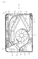
- FIG. 1 is a cross-sectional view illustrating an indoor unit 10 of an air conditioner according to an embodiment.
- the indoor unit 10 of the air conditioner includes a chassis 11, a main body, a base 12, and a front panel 14.
- a flow guide 111 for generating airflow is provided on a front surface of the chassis 11.
- the main body includes a front frame 13 coupled to a front portion of the chassis 11.
- An intake grill 131 is provided on an upper surface of the front frame 13.
- the base 12 is rotatably coupled to a back surface of the chassis 11 and fixed to an installation wall surface.
- the front panel 14 is movably coupled to a front surface of the front frame 13.
- the indoor unit 10 further includes an inner panel 15, a heat exchanger 19, a fan 20, and a discharge grill 16.
- the inner panel 15 is link-coupled to a back surface of the front panel 14 and rotatably provided to the front frame 13.
- the heat exchanger 19 is disposed between the front frame 13 and the chassis 11.
- the fan 20 is provided at a lower side of the heat exchanger 19 to suck and discharge indoor air.
- the discharge grill 16 supports a lower end of the heat exchanger 19 and includes a discharge hole.
- the indoor unit 10 further includes a discharge vane 21, a discharge louver 22, a bottom plate 23, and a holder member 24.
- the discharge vane 21 selectively shields the discharge hole.
- the discharge louver 22 is provided in the discharge hole to adjust a discharge direction of air together with the discharge vane 21.
- the bottom plate 23 shields a piping passing through a lower end of the indoor unit 10.
- the holder member 24 is rotatably coupled to the chassis 11 and supports the piping.
- the discharge vane 21 and the discharge louver 22 may be driven by a motor.
- the indoor unit 10 further includes a pre-filter 17 and a dust-collecting filter 18.
- the pre-filter 17 filters air sucked through the front surface of the front frame 13 and the intake grill 131.
- the dust-collecting filter 18 is provided between the pre-filter 17 and the heat exchanger 19.
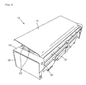
- FIG. 2 is a perspective view of an indoor unit in which a signal receiver is installed according to an embodiment.
- a signal receiver 40 according to an embodiment is installed on a bottom surface of the indoor unit 10.
- the signal receiver 40 protrudes from the bottom surface of the indoor unit 10 in order to improve reception sensitivity.
- a sensor that will be described later
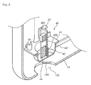
- FIGS. 3 and 4 are perspective views of a process in which a signal receiver is installed in an indoor unit according to an embodiment
- FIG. 5 is a cross-sectional view taken along line I-I' of FIG. 4 .
- the signal receiver 40 is installed on a bottom surface around an edge of a side of the front frame 13.
- edges of both sides of the front frame 13 are bent several times to define an upper surface, a front surface, and a bottom surface.
- a mounting hole 132 in which the signal receiver 40 is inserted is defined in the bottom surface of the front frame 13.
- a plurality of coupling ribs 133 is disposed apart by a predetermined distance on an inner surface of the mounting hole 132.
- a stopper 134 extends at an upper side of the bottom surface of the front frame in which the mounting hole is defined. The stopper 134 extends radially from an edge of the mounting hole 132.
- the stopper 134 is a protrusion for setting a rotation limit when the signal receiver 40 is installed.
- the signal receiver 40 includes a housing 42, a bracket 41, and a circuit board 43.
- the housing 42 receives a sensor 44 for receiving a command signal.
- the bracket 41 extends laterally from the housing 42 and is closely attached to the bottom surface of the front frame 13.
- the circuit board 43 is vertically inserted inside the housing 42.
- the sensor 44 is attached to a lower end of one surface of the circuit board 43.
- the bracket 41 and the housing 42 may be injection-molded in one body, or separately provided to couple the bracket 41 to the housing 42.
- a plurality of coupling protrusions 421 is arranged on an outer surface of the housing 42. The coupling protrusions 421 interfere with the coupling ribs 133 to allow the signal receiver 40 to be fixed to the mounting hole 132.
- a support rib for supporting the circuit board 43 protrudes from a bottom surface of the housing 42.
- the housing 42 has a length greater than a thickness of a lower surface portion of the front frame 13.
- the sensor 44 may protrude from the indoor unit 10 to the outside.
- the circuit board 43 has a mounting surface 431 on which the sensor 44 is mounted.
- the mounting surface 431 is perpendicular to the bottom surface of the housing 42 in a state where the circuit board 43 is mounted on the housing 42.
- FIG. 6 is a view of a state in which a signal receiver is inserted into a mounting hole according to an embodiment
- FIG. 7 is a view of a state in which the signal receiver is completely installed.
- the housing 42 is inserted into the mounting hole 132.
- the coupling protrusions 421 disposed apart by the predetermined distance on the outer surface of the housing 42 pass through the coupling ribs 133 protruding from the inner surface of the mounting hole 132.
- the bracket 41 is pushed into the mounting hole 132 until the bracket is closely attached to the bottom surface of the front frame 13.
- top surfaces of the coupling protrusions 421 have the same height as bottom surfaces of the coupling ribs 133.
- the signal receiver 40 is rotated in a clockwise direction or a counter-clockwise direction until the bracket 41 is hung on the stopper 134.
- the top surfaces of the coupling protrusions 421 are hung on the bottom surfaces of the coupling ribs 133 to complete the installation of the signal receiver 40.
- a separate process of the signal receiver 40 is performed in reverse order of the installation process thereof.
- the circuit board 43 is detachably coupled to the support rib 422.
- the circuit board 43 constituting the signal receiver 40 can be vertically disposed inside the housing 42, the sensor 44 can be maximally close to the bottom surface of the housing 42.
- the circuit board 43 since the circuit board 43 must be horizontally disposed, the sensor 44 was spaced from the bottom surface of the housing 42 to the inside of the indoor unit 40. Therefore, there is a limitation that the reception sensitivity is reduced.
- the sensor 44 when the sensor 44 is installed on a lower end of the circuit board 43 and vertically disposed inside the housing 42, the sensor 44 can protrude from the bottom surface of the indoor unit 10 to improve the reception sensitivity.
Landscapes
- Engineering & Computer Science (AREA)
- Chemical & Material Sciences (AREA)
- Combustion & Propulsion (AREA)
- Mechanical Engineering (AREA)
- General Engineering & Computer Science (AREA)
- Physics & Mathematics (AREA)
- Thermal Sciences (AREA)
- Air Conditioning Control Device (AREA)
- Air Filters, Heat-Exchange Apparatuses, And Housings Of Air-Conditioning Units (AREA)
Abstract
Description
- Embodiments relate to an indoor unit of an air conditioner.
- Generally, an air conditioner is a cooling/heating apparatus that cools or heats air within an inner space of a building, etc.
- The air conditioner includes an outdoor unit receiving a compressor and an indoor unit installed at an indoor space to perform heat-exchange between air and refrigerant. According to the types of air conditioners, the indoor unit and the outdoor unit may be integrated in one body.
- An indoor heat exchanger, a fan assembly, and a filter for filtering sucked air are installed in the indoor unit. The indoor unit is classified into a wall-mounted type, a floor-mounted type, and a window type according to an installation position thereof.
- The indoor unit may operate by receiving a signal of a remote controller. For this, the indoor unit includes a signal receiver for receiving the signal of the remote controller.
- Embodiments provide an indoor unit of an air conditioner capable of improving reception sensitivity of a signal transmitted from a remote controller.
- In one embodiment, an indoor unit of an air conditioner includes: a main body receiving a heat exchanger and a fan; and a signal receiver protruding from a bottom surface of the main body to receive a wireless signal, wherein the signal receiver comprises: a sensor for receiving a signal; a circuit board to which the sensor is attached; and a housing in which the circuit board is installed, and wherein the circuit board is disposed perpendicular to the housing.
- The details of one or more embodiments are set forth in the accompanying drawings and the description below. Other features will be apparent from the description and drawings, and from the claims.
-
-
FIG. 1 is a cross-sectional view illustrating an indoor unit of an air conditioner according to an embodiment. -
FIG. 2 is a perspective view of an indoor unit in which a signal receiver is installed according to an embodiment. -
FIGS. 3 and4 are perspective views of a process in which a signal receiver is installed in an indoor unit according to an embodiment. -
FIG. 5 is a cross-sectional view taken along line I-I' ofFIG. 4 . -
FIG. 6 is a view of a state in which a signal receiver is inserted into a mounting hole according to an embodiment. -
FIG. 7 is a view of a state in which the signal receiver is completely installed. - Reference will now be made in detail to the embodiments of the present disclosure, examples of which are illustrated in the accompanying drawings.
- In the following detailed description of the preferred embodiments, reference is made to the accompanying drawings that form a part hereof, and in which is shown by way of illustration specific preferred embodiments in which the invention may be practiced. These embodiments are described in sufficient detail to enable those skilled in the art to practice the invention, and it is understood that other embodiments may be utilized and that logical structural, mechanical, electrical, and chemical changes may be made without departing from the spirit or scope of the invention. To avoid detail not necessary to enable those skilled in the art to practice the invention, the description may omit certain information known to those skilled in the art. The following detailed description is, therefore, not to be taken in a limiting sense, and the scope of the present invention is defined only by the appended claims.
-
FIG. 1 is a cross-sectional view illustrating anindoor unit 10 of an air conditioner according to an embodiment. - Referring to
FIG. 1 , theindoor unit 10 of the air conditioner includes achassis 11, a main body, abase 12, and afront panel 14. Aflow guide 111 for generating airflow is provided on a front surface of thechassis 11. The main body includes afront frame 13 coupled to a front portion of thechassis 11. Anintake grill 131 is provided on an upper surface of thefront frame 13. Thebase 12 is rotatably coupled to a back surface of thechassis 11 and fixed to an installation wall surface. Thefront panel 14 is movably coupled to a front surface of thefront frame 13. - The
indoor unit 10 further includes aninner panel 15, aheat exchanger 19, afan 20, and adischarge grill 16. Theinner panel 15 is link-coupled to a back surface of thefront panel 14 and rotatably provided to thefront frame 13. Theheat exchanger 19 is disposed between thefront frame 13 and thechassis 11. Thefan 20 is provided at a lower side of theheat exchanger 19 to suck and discharge indoor air. Thedischarge grill 16 supports a lower end of theheat exchanger 19 and includes a discharge hole. - The
indoor unit 10 further includes adischarge vane 21, adischarge louver 22, abottom plate 23, and aholder member 24. The discharge vane 21 selectively shields the discharge hole. Thedischarge louver 22 is provided in the discharge hole to adjust a discharge direction of air together with thedischarge vane 21. Thebottom plate 23 shields a piping passing through a lower end of theindoor unit 10. Theholder member 24 is rotatably coupled to thechassis 11 and supports the piping. Although not shown, thedischarge vane 21 and thedischarge louver 22 may be driven by a motor. - The
indoor unit 10 further includes a pre-filter 17 and a dust-collecting filter 18. The pre-filter 17 filters air sucked through the front surface of thefront frame 13 and theintake grill 131. The dust-collectingfilter 18 is provided between the pre-filter 17 and theheat exchanger 19. -
FIG. 2 is a perspective view of an indoor unit in which a signal receiver is installed according to an embodiment. - Referring to
FIG. 2 , asignal receiver 40 according to an embodiment is installed on a bottom surface of theindoor unit 10. Thesignal receiver 40 protrudes from the bottom surface of theindoor unit 10 in order to improve reception sensitivity. Thus, since a sensor (that will be described later) constituting thesignal receiver 40 protrudes outside theindoor unit 10, the signal reception sensitivity is improved. -
FIGS. 3 and4 are perspective views of a process in which a signal receiver is installed in an indoor unit according to an embodiment, andFIG. 5 is a cross-sectional view taken along line I-I' ofFIG. 4 . - Referring to
FIGS. 3 to 5 , thesignal receiver 40 is installed on a bottom surface around an edge of a side of thefront frame 13. - In detail, edges of both sides of the
front frame 13 are bent several times to define an upper surface, a front surface, and a bottom surface. Amounting hole 132 in which thesignal receiver 40 is inserted is defined in the bottom surface of thefront frame 13. A plurality ofcoupling ribs 133 is disposed apart by a predetermined distance on an inner surface of themounting hole 132. Astopper 134 extends at an upper side of the bottom surface of the front frame in which the mounting hole is defined. Thestopper 134 extends radially from an edge of themounting hole 132. - The
stopper 134 is a protrusion for setting a rotation limit when thesignal receiver 40 is installed. - The
signal receiver 40 includes ahousing 42, abracket 41, and acircuit board 43. Thehousing 42 receives asensor 44 for receiving a command signal. Thebracket 41 extends laterally from thehousing 42 and is closely attached to the bottom surface of thefront frame 13. Thecircuit board 43 is vertically inserted inside thehousing 42. Thesensor 44 is attached to a lower end of one surface of thecircuit board 43. - In detail, the
bracket 41 and thehousing 42 may be injection-molded in one body, or separately provided to couple thebracket 41 to thehousing 42. A plurality ofcoupling protrusions 421 is arranged on an outer surface of thehousing 42. The coupling protrusions 421 interfere with thecoupling ribs 133 to allow thesignal receiver 40 to be fixed to the mountinghole 132. A support rib for supporting thecircuit board 43 protrudes from a bottom surface of thehousing 42. - In detail, the
housing 42 has a length greater than a thickness of a lower surface portion of thefront frame 13. Thus, when thesignal receiver 40 is installed, thesensor 44 may protrude from theindoor unit 10 to the outside. - The
circuit board 43 has a mountingsurface 431 on which thesensor 44 is mounted. The mountingsurface 431 is perpendicular to the bottom surface of thehousing 42 in a state where thecircuit board 43 is mounted on thehousing 42. - Hereinafter, a coupling process of the
signal receiver 40 will be described in detail with reference to the drawings. -
FIG. 6 is a view of a state in which a signal receiver is inserted into a mounting hole according to an embodiment, andFIG. 7 is a view of a state in which the signal receiver is completely installed. - Referring to
FIGS. 6 and7 , for installing thesignal receiver 40, first, thehousing 42 is inserted into the mountinghole 132. - The coupling protrusions 421 disposed apart by the predetermined distance on the outer surface of the
housing 42 pass through thecoupling ribs 133 protruding from the inner surface of the mountinghole 132. Thebracket 41 is pushed into the mountinghole 132 until the bracket is closely attached to the bottom surface of thefront frame 13. As a result, top surfaces of thecoupling protrusions 421 have the same height as bottom surfaces of thecoupling ribs 133. - In this state, the
signal receiver 40 is rotated in a clockwise direction or a counter-clockwise direction until thebracket 41 is hung on thestopper 134. As a result, the top surfaces of thecoupling protrusions 421 are hung on the bottom surfaces of thecoupling ribs 133 to complete the installation of thesignal receiver 40. A separate process of thesignal receiver 40 is performed in reverse order of the installation process thereof. Thecircuit board 43 is detachably coupled to thesupport rib 422. - Thus, in order to replace the
signal receiver 40, only thecircuit board 43 may be separated, or thehousing 42 itself may be separated from thefront frame 13. - As described above, since the
circuit board 43 constituting thesignal receiver 40 can be vertically disposed inside thehousing 42, thesensor 44 can be maximally close to the bottom surface of thehousing 42. In a related art, since thecircuit board 43 must be horizontally disposed, thesensor 44 was spaced from the bottom surface of thehousing 42 to the inside of theindoor unit 40. Therefore, there is a limitation that the reception sensitivity is reduced. - However, as described in the embodiment, when the
sensor 44 is installed on a lower end of thecircuit board 43 and vertically disposed inside thehousing 42, thesensor 44 can protrude from the bottom surface of theindoor unit 10 to improve the reception sensitivity. - While the present disclose has been particularly shown and described with reference to exemplary embodiments thereof, it will be understood by those of ordinary skill in the art that various changes in form and details may be made therein without departing from the scope of the present disclose as defined by the following claims.
Claims (8)
- An indoor unit of an air conditioner, the indoor unit comprising:a main body receiving a heat exchanger and a fan; anda signal receiver protruding from a bottom surface of the main body to receive a wireless signal,wherein the signal receiver comprises:a sensor for receiving a signal;a circuit board to which the sensor is attached; anda housing in which the circuit board is installed, andwherein the circuit board is disposed perpendicular to the housing.
- The indoor unit according to claim 1, wherein a mounting hole in which the housing is installed is defined in a bottom surface of the main body, and at least portion of the housing protrudes from the bottom surface of the main body.
- The indoor unit according to claim 2, wherein a plurality of coupling ribs is disposed on an inner surface of the mounting hole, and a plurality of coupling protrusions respectively hung on the coupling ribs is disposed on an outer surface of the housing.
- The indoor unit according to claim 3, wherein the coupling protrusions are respectively hung on the coupling ribs because the housing is rotated in a state where the housing is inserted into the mounting hole.
- The indoor unit according to claim 2, wherein a support rib for supporting the circuit board protrudes from a bottom surface of the housing, and the circuit board is separably coupled to the support rib.
- The indoor unit according to claim 2, further comprising a bracket extending in a horizontal direction of the housing,
wherein the bracket is close to an upper portion of the bottom surface of the main body in a state where the housing passes through the mounting hole. - The indoor unit according to claim 1, wherein a mounting surface on which the sensor is mounted is defined on the circuit board, and the mounting surface is perpendicular to a bottom surface of the housing in a state where the circuit board is installed inside the housing.
- The indoor unit according to claim 7, wherein the sensor is installed on a lower side portion of the mounting surface.
Applications Claiming Priority (1)
| Application Number | Priority Date | Filing Date | Title |
|---|---|---|---|
| KR1020080110790A KR101590632B1 (en) | 2008-11-10 | 2008-11-10 | Indoor unit for air conditioning apparatus |
Publications (1)
| Publication Number | Publication Date |
|---|---|
| EP2184552A1 true EP2184552A1 (en) | 2010-05-12 |
Family
ID=41651523
Family Applications (1)
| Application Number | Title | Priority Date | Filing Date |
|---|---|---|---|
| EP09250129A Withdrawn EP2184552A1 (en) | 2008-11-10 | 2009-01-19 | Indoor unit of air conditioner |
Country Status (3)
| Country | Link |
|---|---|
| EP (1) | EP2184552A1 (en) |
| KR (1) | KR101590632B1 (en) |
| CN (1) | CN101737911A (en) |
Cited By (1)
| Publication number | Priority date | Publication date | Assignee | Title |
|---|---|---|---|---|
| JP2013120035A (en) * | 2011-12-08 | 2013-06-17 | Fujitsu General Ltd | Air conditioner |
Families Citing this family (1)
| Publication number | Priority date | Publication date | Assignee | Title |
|---|---|---|---|---|
| CN110193158B (en) * | 2019-05-28 | 2020-11-13 | 诸暨易和项目投资有限公司 | Underground fire-fighting device |
Citations (8)
| Publication number | Priority date | Publication date | Assignee | Title |
|---|---|---|---|---|
| JPH11325560A (en) * | 1998-05-08 | 1999-11-26 | Funai Electric Co Ltd | Power switch device in remote control type electronic apparatus |
| US6189328B1 (en) * | 1997-11-28 | 2001-02-20 | Matsushita Electric Industrial Co., Ltd. | Separate type air conditioner and assembly method thereof |
| JP2002089876A (en) * | 2000-09-12 | 2002-03-27 | Sharp Corp | Indoor unit of air conditioner |
| JP2003090588A (en) * | 2001-09-20 | 2003-03-28 | Fujitsu General Ltd | Remote controller of air conditioner |
| JP2003232534A (en) * | 2002-02-08 | 2003-08-22 | Sanyo Electric Co Ltd | Ceiling embedded air conditioner |
| WO2006075730A1 (en) | 2005-01-17 | 2006-07-20 | Toshiba Carrier Corporation | Indoor unit of air conditioner |
| EP1795819A1 (en) * | 2004-09-30 | 2007-06-13 | Toshiba Carrier Corporation | Air conditioner |
| JP2008145062A (en) * | 2006-12-11 | 2008-06-26 | Daikin Ind Ltd | Indoor unit of air conditioner |
-
2008
- 2008-11-10 KR KR1020080110790A patent/KR101590632B1/en active IP Right Grant
-
2009
- 2009-01-19 EP EP09250129A patent/EP2184552A1/en not_active Withdrawn
- 2009-02-13 CN CN200910007209A patent/CN101737911A/en active Pending
Patent Citations (8)
| Publication number | Priority date | Publication date | Assignee | Title |
|---|---|---|---|---|
| US6189328B1 (en) * | 1997-11-28 | 2001-02-20 | Matsushita Electric Industrial Co., Ltd. | Separate type air conditioner and assembly method thereof |
| JPH11325560A (en) * | 1998-05-08 | 1999-11-26 | Funai Electric Co Ltd | Power switch device in remote control type electronic apparatus |
| JP2002089876A (en) * | 2000-09-12 | 2002-03-27 | Sharp Corp | Indoor unit of air conditioner |
| JP2003090588A (en) * | 2001-09-20 | 2003-03-28 | Fujitsu General Ltd | Remote controller of air conditioner |
| JP2003232534A (en) * | 2002-02-08 | 2003-08-22 | Sanyo Electric Co Ltd | Ceiling embedded air conditioner |
| EP1795819A1 (en) * | 2004-09-30 | 2007-06-13 | Toshiba Carrier Corporation | Air conditioner |
| WO2006075730A1 (en) | 2005-01-17 | 2006-07-20 | Toshiba Carrier Corporation | Indoor unit of air conditioner |
| JP2008145062A (en) * | 2006-12-11 | 2008-06-26 | Daikin Ind Ltd | Indoor unit of air conditioner |
Cited By (1)
| Publication number | Priority date | Publication date | Assignee | Title |
|---|---|---|---|---|
| JP2013120035A (en) * | 2011-12-08 | 2013-06-17 | Fujitsu General Ltd | Air conditioner |
Also Published As
| Publication number | Publication date |
|---|---|
| KR101590632B1 (en) | 2016-02-01 |
| KR20100051958A (en) | 2010-05-19 |
| CN101737911A (en) | 2010-06-16 |
Similar Documents
| Publication | Publication Date | Title |
|---|---|---|
| EP3124888B1 (en) | Indoor unit of air conditioner | |
| EP2184553B1 (en) | Indoor unit of air conditioner | |
| EP2299191A2 (en) | Indoor unit of air conditioner | |
| CN106196332B (en) | Outdoor unit of air conditioner | |
| EP2184551A2 (en) | Indoor unit of air conditioner | |
| EP2184550A2 (en) | Indoor unit of air conditioner | |
| EP2184552A1 (en) | Indoor unit of air conditioner | |
| KR20070066393A (en) | Housing of indoor unit for ceiling duct type air conditioner | |
| KR20100051957A (en) | Indoor unit for air conditioning apparatus | |
| AU2019326098A1 (en) | Air conditioner | |
| KR102361294B1 (en) | Indoor unit for air conditioner | |
| KR20180066546A (en) | Air conditioner | |
| WO2008078906A2 (en) | Controller assembly of air conditioner | |
| CN211854233U (en) | Window type air conditioner | |
| KR100547689B1 (en) | Fan motor fixing structure of integrated air conditioner | |
| KR100347931B1 (en) | Air cleaner setting for air conditioner | |
| KR101409014B1 (en) | Indoor unit for cassette type air conditioner | |
| KR20090022102A (en) | Air conditioner | |
| KR100701930B1 (en) | Structure of arraying a hose in stand type air-conditioner | |
| CN101334192A (en) | Chassis of indoor machine of split wall-mount air-conditioner | |
| CN109425022B (en) | Air conditioner all-in-one machine | |
| KR101105756B1 (en) | Installing Structure of Front panel for Airconditioner | |
| KR100509052B1 (en) | Front panel mounting structure of Airconditioner | |
| KR101072549B1 (en) | Indoor unit for air-conditioner | |
| CN114423996A (en) | Wall-mounted air conditioner indoor unit |
Legal Events
| Date | Code | Title | Description |
|---|---|---|---|
| PUAI | Public reference made under article 153(3) epc to a published international application that has entered the european phase |
Free format text: ORIGINAL CODE: 0009012 |
|
| AK | Designated contracting states |
Kind code of ref document: A1 Designated state(s): AT BE BG CH CY CZ DE DK EE ES FI FR GB GR HR HU IE IS IT LI LT LU LV MC MK MT NL NO PL PT RO SE SI SK TR |
|
| AX | Request for extension of the european patent |
Extension state: AL BA RS |
|
| 17P | Request for examination filed |
Effective date: 20101109 |
|
| AKX | Designation fees paid |
Designated state(s): AT BE BG CH CY CZ DE DK EE ES FI FR GB GR HR HU IE IS IT LI LT LU LV MC MK MT NL NO PL PT RO SE SI SK TR |
|
| RIC1 | Information provided on ipc code assigned before grant |
Ipc: F24F 11/02 20060101ALI20110211BHEP Ipc: F24F 1/00 20110101AFI20110211BHEP |
|
| GRAP | Despatch of communication of intention to grant a patent |
Free format text: ORIGINAL CODE: EPIDOSNIGR1 |
|
| STAA | Information on the status of an ep patent application or granted ep patent |
Free format text: STATUS: THE APPLICATION IS DEEMED TO BE WITHDRAWN |
|
| 18D | Application deemed to be withdrawn |
Effective date: 20110819 |