EP1165971B1 - Halter - Google Patents
Halter Download PDFInfo
- Publication number
- EP1165971B1 EP1165971B1 EP00911538A EP00911538A EP1165971B1 EP 1165971 B1 EP1165971 B1 EP 1165971B1 EP 00911538 A EP00911538 A EP 00911538A EP 00911538 A EP00911538 A EP 00911538A EP 1165971 B1 EP1165971 B1 EP 1165971B1
- Authority
- EP
- European Patent Office
- Prior art keywords
- locking
- holder
- locking element
- unit
- shaft
- Prior art date
- Legal status (The legal status is an assumption and is not a legal conclusion. Google has not performed a legal analysis and makes no representation as to the accuracy of the status listed.)
- Expired - Lifetime
Links
- 238000003780 insertion Methods 0.000 claims abstract description 3
- 230000037431 insertion Effects 0.000 claims abstract description 3
- 230000001939 inductive effect Effects 0.000 claims abstract 2
- 150000001875 compounds Chemical class 0.000 description 1
- 238000001802 infusion Methods 0.000 description 1
- 230000000241 respiratory effect Effects 0.000 description 1
Images

Classifications
-
- F—MECHANICAL ENGINEERING; LIGHTING; HEATING; WEAPONS; BLASTING
- F16—ENGINEERING ELEMENTS AND UNITS; GENERAL MEASURES FOR PRODUCING AND MAINTAINING EFFECTIVE FUNCTIONING OF MACHINES OR INSTALLATIONS; THERMAL INSULATION IN GENERAL
- F16B—DEVICES FOR FASTENING OR SECURING CONSTRUCTIONAL ELEMENTS OR MACHINE PARTS TOGETHER, e.g. NAILS, BOLTS, CIRCLIPS, CLAMPS, CLIPS OR WEDGES; JOINTS OR JOINTING
- F16B21/00—Means for preventing relative axial movement of a pin, spigot, shaft or the like and a member surrounding it; Stud-and-socket releasable fastenings
- F16B21/02—Releasable fastening devices locking by rotation
Definitions
- the present invention relates to a holder according to the preamble to claim 1, see e.g. US-A- 5 044 856.
- connection When different components are interconnected, such as instruments on devices, rails etc., the connection must be firm and stable. It would also be advantageous if assembly, disassembly and holder repositioning could be performed quickly and simply.
- One objective of the present invention is to achieve a holder with the desired characteristics.
- a design with simultaneous axial motion and locking rotation makes it possible to devise a locking element for axial insertion into a groove or corresponding receiving part in the unit to which the holder is to be connected.
- the locking element is then screwed in, whereupon a bevelled shoulder or shoulders force(s) the locking device to rotate and assume a locking position against contact surfaces in the receiving part. This greatly facilitates both assembly and disassembly.
- the number of components in the locking device is kept to a minimum.
- FIGS. 1 and 2 illustrate the locking principle of the holder according to the invention, and the following description therefore refers to both.
- the holder comprises a load-bearing part 2 that, in this instance, has been brought to bear against a first unit 4 for connection.
- At least one or preferably two bevelled shoulders 12 are arranged in the load-bearing part 2. The bevelled shoulders 12 are arranged in such a way that the locking element 10 is forced to rotate when the handle 8 performs an axial movement.
- the first unit 4 comprises a channel 14.
- the channel 14 is preferably longitudinal and can e.g. consist of a groove, such as a T groove.
- the first unit 4 has edges 16 at the opening of the channel 14 making the opening narrower than the channel 14.
- the widths of the opening and the locking element 10 are tailored to each other to enable the locking element 10 to be inserted through the opening.
- the locking element 10 is accordingly inserted into the channel 14 through the opening in the first unit 4.
- the handle 8 is then rotated, thereby screwing the locking shaft 6 into the handle 8.
- the locking element 10 is then pulled against the bevelled shoulders 12, forcing the locking element 10 to rotate.
- the rotation causes part of the locking element 10 to come into contact with the edges 16, and they are clamped between the load-bearing part 2 and the locking element 10, thereby connecting the holder to the first unit 4.
- the handle 8 is turned in the opposite direction to unscrew the locking shaft 6.
- the locking element 10 can then be lifted off the bevelled shoulders 12 and turned back to its original position.
- the holder can then be easily detached from the first unit 4.
- a torsion bar 18 is arranged in the load-bearing part 2 and attached to the locking shaft 6.
- the torsion bar 18 is set up so it tensions when the locking element 10 is rotated during locking.
- the holder could also contain a pressure spring that exerts axial pressure on the locking element 10 when the holder is to be detached. However, this is not shown in the figures.
- FIG. 3 shows a conjoined locking element 10 and locking shaft 6. It clearly shows the threaded part of the locking shaft 6.
- the use of a compound component means that the holder has fewer parts and is easier to fabricate and assemble.
- the depicted design for the locking element 10 also comprises a bevel 20A, 20B on both sides.
- the contact surfaces 22A, 22B, which will press against the edges of the first unit, are arranged at the bevels 20A, 20B.
- These bevels 20A, 20B enable the locking element 10 to be relatively tall, thereby increasing handle stability.
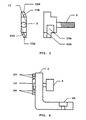
- FIG. 4 shows a version of the holder for the attachment of additional units (not shown in the FIG.)
- the load-bearing part 2 is essentially L-shaped in this instance.
- the handle 8 with the locking device (only the locking element 10 is visible) is on one leg.
- Guiding means 24 are also arranged on the load-bearing part 2. In connection to the first unit, they are also inserted into the opening to contribute stability when the entire handle is subjected to torsional loading.
- a connector part 26 for additional units is arranged on the other leg of the load-bearing part 2. They can be e.g. screwed onto the load-bearing part 2.
- the holder can be connected to a T-groove rail (or the like) carrying a carriage for a respirator. Articulated arms can then be attached to the holder to hold infusion bags or different kinds of instruments. However, the holder can be used in all areas in which detachable connection of different units is desired.
Landscapes
- Engineering & Computer Science (AREA)
- General Engineering & Computer Science (AREA)
- Mechanical Engineering (AREA)
- Clamps And Clips (AREA)
- Quick-Acting Or Multi-Walled Pipe Joints (AREA)
- Snaps, Bayonet Connections, Set Pins, And Snap Rings (AREA)
- Valve-Gear Or Valve Arrangements (AREA)
- Lasers (AREA)
- Electrical Discharge Machining, Electrochemical Machining, And Combined Machining (AREA)
- Laser Surgery Devices (AREA)
- Paper (AREA)
Claims (5)
- Ein Halter zum Befestigen an einer ersten Einheit (4) mit einer Feststellvorrichtung (6, 8, 10), bestimmt für das Einführen, in einer ersten Lage, in ein Aufnahmeteil (14) in der ersten Einheit (4) und zum Arretieren, in einer zweiten Lage, des Halters an der ersten Einheit (4), wobei die Feststellvorrichtung (6, 8, 10) eine Gewindestange (6), die zu axialer Bewegung im Halter imstande ist, einen Griff (8) mit einem Gewindeloch zur Aufnahme der Gewindestange (6) und ein starr mit der Arretierstange verbundenes Feststellelement (10) aufweist, dadurch gekennzeichnet, dass der Halter zumindest einen abgeschrägten Ansatz (12) aufweist, gegen den das Feststellelement (10) axial bewegbar ist, wobei der Griff (8), wenn er zum Arretieren gedreht wird, die Arretierstange (6) ebenso wie das Feststellelement (10) axial gegen den/die abgeschrägten Ansatz/Ansätze (12) zieht, wodurch das Feststellelement (10) gleichzeitig zur Rotation veranlasst wird, um den Halter in dem Aufnahmeteil (4) zu arretieren.
- Der Halter nach Anspruch 1, dadurch gekennzeichnet, dass zumindest eine Feder (18) in dem Halter angeordnet und mit dem Feststellelement (10) verbunden ist, um das Feststellelement (10) in seine Ursprungslage zurückzuführen, wenn der Griff (8) gedreht wird, um es zu lösen.
- Der Halter nach Anspruch 1 oder 2, dadurch gekennzeichnet, dass die Arretierstange (6) und das Feststellelement (10) einteilig ausgebildet sind.
- Der Halter nach einem der obigen Ansprüche, dadurch gekennzeichnet, dass der Halter auch ein Halterteil (26) für zumindest eine zweite Einheit aufweist.
- Ein Aufnahmeteil (4) zum Arretieren eines Halters gemäß einem der Ansprüche 1-4, dadurch gekennzeichnet, dass das Aufnahmeteil (4) mit einem weitgehend längslaufenden Kanal (14) ausgebildet ist, der tief genug ist, das Feststellelement (10) aufzunehmen, und Flanken (16) hat, gegen die das Feststellelement (10) durch die Dreh- und Axialbewegung gespannt wird.
Applications Claiming Priority (3)
| Application Number | Priority Date | Filing Date | Title |
|---|---|---|---|
| SE9901119A SE9901119L (sv) | 1999-03-26 | 1999-03-26 | Fäste och mottagardel för låsning av ett fäste |
| SE9901119 | 1999-03-26 | ||
| PCT/SE2000/000363 WO2000058634A1 (en) | 1999-03-26 | 2000-02-24 | Holder |
Publications (2)
| Publication Number | Publication Date |
|---|---|
| EP1165971A1 EP1165971A1 (de) | 2002-01-02 |
| EP1165971B1 true EP1165971B1 (de) | 2004-04-14 |
Family
ID=20415025
Family Applications (1)
| Application Number | Title | Priority Date | Filing Date |
|---|---|---|---|
| EP00911538A Expired - Lifetime EP1165971B1 (de) | 1999-03-26 | 2000-02-24 | Halter |
Country Status (8)
| Country | Link |
|---|---|
| US (1) | US6520725B1 (de) |
| EP (1) | EP1165971B1 (de) |
| JP (1) | JP4646169B2 (de) |
| AT (1) | ATE264464T1 (de) |
| AU (1) | AU3340300A (de) |
| DE (1) | DE60009887T2 (de) |
| SE (1) | SE9901119L (de) |
| WO (1) | WO2000058634A1 (de) |
Families Citing this family (3)
| Publication number | Priority date | Publication date | Assignee | Title |
|---|---|---|---|---|
| DE20202681U1 (de) * | 2002-02-21 | 2002-05-08 | Schwarz Verbindungs Sys Gmbh | Lösbare Einsatz-Verbindungsanordnung für eine Halte-Nut |
| TW200920232A (en) * | 2007-10-16 | 2009-05-01 | Inventec Corp | Locking device |
| CN103918624B (zh) * | 2013-01-15 | 2015-12-16 | 浙江泰普森休闲用品有限公司 | 搁杆叉基座和搁杆叉 |
Family Cites Families (10)
| Publication number | Priority date | Publication date | Assignee | Title |
|---|---|---|---|---|
| US3152822A (en) * | 1961-10-16 | 1964-10-13 | Camloc Fastener Corp | Push button fastener |
| JPS61142907U (de) * | 1985-02-27 | 1986-09-03 | ||
| DE3610868A1 (de) * | 1986-04-01 | 1987-10-08 | Camloc Gmbh | Drehverschluss zur verbindung plattenfoermiger bauteile |
| US4827609A (en) | 1987-06-16 | 1989-05-09 | Mars Incorporated | Method and apparatus for mounting components on a printed circuit board or similar mounting surface |
| US5044856A (en) * | 1989-06-21 | 1991-09-03 | Protoned B.V. | Fastening element secured against rotation for a structural part to be removably attached to a supporting arrangement |
| US5142834A (en) * | 1990-07-12 | 1992-09-01 | Donnelly Corporation | Vehicle trim assembly and fastener therefor |
| US5123795A (en) * | 1990-08-29 | 1992-06-23 | Donaldson Company, Inc. | Quarter turn fastener |
| EP0536923A1 (de) | 1991-10-07 | 1993-04-14 | Emhart Inc. | Hänger |
| US5370488A (en) * | 1993-11-12 | 1994-12-06 | Sykes; Christopher C. | Connector |
| US5593265A (en) * | 1995-08-16 | 1997-01-14 | Chrysler Corporation | Quick-connect stored energy torsional fastener |
-
1999
- 1999-03-26 SE SE9901119A patent/SE9901119L/ not_active IP Right Cessation
-
2000
- 2000-02-24 US US09/913,607 patent/US6520725B1/en not_active Expired - Lifetime
- 2000-02-24 AU AU33403/00A patent/AU3340300A/en not_active Abandoned
- 2000-02-24 WO PCT/SE2000/000363 patent/WO2000058634A1/en active IP Right Grant
- 2000-02-24 EP EP00911538A patent/EP1165971B1/de not_active Expired - Lifetime
- 2000-02-24 AT AT00911538T patent/ATE264464T1/de not_active IP Right Cessation
- 2000-02-24 DE DE60009887T patent/DE60009887T2/de not_active Expired - Lifetime
- 2000-02-24 JP JP2000608098A patent/JP4646169B2/ja not_active Expired - Fee Related
Also Published As
| Publication number | Publication date |
|---|---|
| DE60009887T2 (de) | 2005-03-31 |
| DE60009887D1 (en) | 2004-05-19 |
| WO2000058634A1 (en) | 2000-10-05 |
| SE9901119D0 (sv) | 1999-03-26 |
| EP1165971A1 (de) | 2002-01-02 |
| JP2002540367A (ja) | 2002-11-26 |
| SE512275C2 (sv) | 2000-02-21 |
| ATE264464T1 (de) | 2004-04-15 |
| AU3340300A (en) | 2000-10-16 |
| JP4646169B2 (ja) | 2011-03-09 |
| US6520725B1 (en) | 2003-02-18 |
| SE9901119L (sv) | 2000-02-21 |
Similar Documents
| Publication | Publication Date | Title |
|---|---|---|
| DE3206789C2 (de) | Gelenkiger Tragarm | |
| EP2008607B1 (de) | Kupplungsvorrichtung zum Festlegen medizinischer Instrumente an einer Haltevorrichtung | |
| EP2146813B1 (de) | Adapter zum betreiben einer lochsäge an einer antriebsmaschine | |
| CN2878763Y (zh) | 一种紧固装置 | |
| EP1033146A3 (de) | Katheterkupplung | |
| MX2007010968A (es) | Dispositivo de aseguramiento para manivela de velocidad para un ensamble de apoyo telescopico para remolque. | |
| CA2549667A1 (en) | Coupling device | |
| DE102012110193A1 (de) | Haltevorrichtung zum lösbaren Befestigen eines Roboters | |
| EP2214269A2 (de) | Schnittstellenvorrichtung | |
| EP1165971B1 (de) | Halter | |
| EP1799533B1 (de) | Befestigung eines adapters für fahrräder | |
| DE10127630C2 (de) | Vorrichtung zur Längeneinstellung, insbesondere einer Fernbetätigung in Kraftfahrzeugen | |
| EP1479925A3 (de) | Sicherungsbolzen, Verriegelungseinrichtung und Zugelement | |
| EP2916764B1 (de) | Instrumentenhalter zum befestigen eines medizinischen instrumentes an einem gelenkarm | |
| EP0316554A1 (de) | Steckvorrichtung für Endoskope | |
| DE20110921U1 (de) | Uterus Manipulator | |
| EP0786617A3 (de) | Verriegelungvorrichtung für eine Rohrverbindung | |
| CA2130681A1 (en) | Releasable clip | |
| EP1634802A3 (de) | Befestigungs-Adapter | |
| DE60104321T2 (de) | Schwerkräfteausgleichvorrichtung für Linearmotor angetriebenes Gleitelement | |
| DE3402585A1 (de) | Handstueck zur aufnahme auswechselbarer dentalwerkzeuge | |
| EP1275890A3 (de) | Rohrbefestigung | |
| DE20309776U1 (de) | Chirurgisches Instrument | |
| CN211343577U (zh) | 一种连接锁 | |
| DE102008044682A1 (de) | Werkzeugsystem, insbesondere für handgeführte Werkzeugmaschinen |
Legal Events
| Date | Code | Title | Description |
|---|---|---|---|
| PUAI | Public reference made under article 153(3) epc to a published international application that has entered the european phase |
Free format text: ORIGINAL CODE: 0009012 |
|
| 17P | Request for examination filed |
Effective date: 20010620 |
|
| AK | Designated contracting states |
Kind code of ref document: A1 Designated state(s): AT BE CH CY DE DK ES FI FR GB GR IE IT LI LU MC NL PT SE |
|
| GRAP | Despatch of communication of intention to grant a patent |
Free format text: ORIGINAL CODE: EPIDOSNIGR1 |
|
| GRAS | Grant fee paid |
Free format text: ORIGINAL CODE: EPIDOSNIGR3 |
|
| GRAA | (expected) grant |
Free format text: ORIGINAL CODE: 0009210 |
|
| RAP1 | Party data changed (applicant data changed or rights of an application transferred) |
Owner name: MAQUET CRITICAL CARE AB |
|
| AK | Designated contracting states |
Kind code of ref document: B1 Designated state(s): AT BE CH CY DE DK ES FI FR GB GR IE IT LI LU MC NL PT SE |
|
| PG25 | Lapsed in a contracting state [announced via postgrant information from national office to epo] |
Ref country code: AT Free format text: LAPSE BECAUSE OF FAILURE TO SUBMIT A TRANSLATION OF THE DESCRIPTION OR TO PAY THE FEE WITHIN THE PRESCRIBED TIME-LIMIT Effective date: 20040414 Ref country code: FI Free format text: LAPSE BECAUSE OF FAILURE TO SUBMIT A TRANSLATION OF THE DESCRIPTION OR TO PAY THE FEE WITHIN THE PRESCRIBED TIME-LIMIT Effective date: 20040414 Ref country code: IT Free format text: LAPSE BECAUSE OF FAILURE TO SUBMIT A TRANSLATION OF THE DESCRIPTION OR TO PAY THE FEE WITHIN THE PRESCRIBED TIME-LIMIT;WARNING: LAPSES OF ITALIAN PATENTS WITH EFFECTIVE DATE BEFORE 2007 MAY HAVE OCCURRED AT ANY TIME BEFORE 2007. THE CORRECT EFFECTIVE DATE MAY BE DIFFERENT FROM THE ONE RECORDED. Effective date: 20040414 Ref country code: LI Free format text: LAPSE BECAUSE OF FAILURE TO SUBMIT A TRANSLATION OF THE DESCRIPTION OR TO PAY THE FEE WITHIN THE PRESCRIBED TIME-LIMIT Effective date: 20040414 Ref country code: CH Free format text: LAPSE BECAUSE OF FAILURE TO SUBMIT A TRANSLATION OF THE DESCRIPTION OR TO PAY THE FEE WITHIN THE PRESCRIBED TIME-LIMIT Effective date: 20040414 Ref country code: BE Free format text: LAPSE BECAUSE OF FAILURE TO SUBMIT A TRANSLATION OF THE DESCRIPTION OR TO PAY THE FEE WITHIN THE PRESCRIBED TIME-LIMIT Effective date: 20040414 Ref country code: NL Free format text: LAPSE BECAUSE OF FAILURE TO SUBMIT A TRANSLATION OF THE DESCRIPTION OR TO PAY THE FEE WITHIN THE PRESCRIBED TIME-LIMIT Effective date: 20040414 |
|
| REG | Reference to a national code |
Ref country code: GB Ref legal event code: FG4D |
|
| REG | Reference to a national code |
Ref country code: CH Ref legal event code: EP |
|
| REF | Corresponds to: |
Ref document number: 60009887 Country of ref document: DE Date of ref document: 20040519 Kind code of ref document: P |
|
| REG | Reference to a national code |
Ref country code: IE Ref legal event code: FG4D |
|
| PG25 | Lapsed in a contracting state [announced via postgrant information from national office to epo] |
Ref country code: GR Free format text: LAPSE BECAUSE OF FAILURE TO SUBMIT A TRANSLATION OF THE DESCRIPTION OR TO PAY THE FEE WITHIN THE PRESCRIBED TIME-LIMIT Effective date: 20040714 Ref country code: DK Free format text: LAPSE BECAUSE OF FAILURE TO SUBMIT A TRANSLATION OF THE DESCRIPTION OR TO PAY THE FEE WITHIN THE PRESCRIBED TIME-LIMIT Effective date: 20040714 Ref country code: SE Free format text: LAPSE BECAUSE OF FAILURE TO SUBMIT A TRANSLATION OF THE DESCRIPTION OR TO PAY THE FEE WITHIN THE PRESCRIBED TIME-LIMIT Effective date: 20040714 |
|
| PG25 | Lapsed in a contracting state [announced via postgrant information from national office to epo] |
Ref country code: ES Free format text: LAPSE BECAUSE OF FAILURE TO SUBMIT A TRANSLATION OF THE DESCRIPTION OR TO PAY THE FEE WITHIN THE PRESCRIBED TIME-LIMIT Effective date: 20040725 |
|
| NLV1 | Nl: lapsed or annulled due to failure to fulfill the requirements of art. 29p and 29m of the patents act | ||
| REG | Reference to a national code |
Ref country code: CH Ref legal event code: PL |
|
| ET | Fr: translation filed | ||
| PLBE | No opposition filed within time limit |
Free format text: ORIGINAL CODE: 0009261 |
|
| STAA | Information on the status of an ep patent application or granted ep patent |
Free format text: STATUS: NO OPPOSITION FILED WITHIN TIME LIMIT |
|
| PG25 | Lapsed in a contracting state [announced via postgrant information from national office to epo] |
Ref country code: LU Free format text: LAPSE BECAUSE OF NON-PAYMENT OF DUE FEES Effective date: 20050224 Ref country code: GB Free format text: LAPSE BECAUSE OF NON-PAYMENT OF DUE FEES Effective date: 20050224 Ref country code: CY Free format text: LAPSE BECAUSE OF FAILURE TO SUBMIT A TRANSLATION OF THE DESCRIPTION OR TO PAY THE FEE WITHIN THE PRESCRIBED TIME-LIMIT Effective date: 20050224 Ref country code: IE Free format text: LAPSE BECAUSE OF NON-PAYMENT OF DUE FEES Effective date: 20050224 |
|
| PG25 | Lapsed in a contracting state [announced via postgrant information from national office to epo] |
Ref country code: MC Free format text: LAPSE BECAUSE OF NON-PAYMENT OF DUE FEES Effective date: 20050228 |
|
| 26N | No opposition filed |
Effective date: 20050117 |
|
| GBPC | Gb: european patent ceased through non-payment of renewal fee |
Effective date: 20050223 |
|
| REG | Reference to a national code |
Ref country code: IE Ref legal event code: MM4A |
|
| PG25 | Lapsed in a contracting state [announced via postgrant information from national office to epo] |
Ref country code: PT Free format text: LAPSE BECAUSE OF NON-PAYMENT OF DUE FEES Effective date: 20040914 |
|
| REG | Reference to a national code |
Ref country code: DE Ref legal event code: R082 Ref document number: 60009887 Country of ref document: DE Representative=s name: SCHAUMBURG & PARTNER PATENTANWAELTE GBR, DE Ref country code: DE Ref legal event code: R082 Ref document number: 60009887 Country of ref document: DE Representative=s name: SCHAUMBURG & PARTNER PATENTANWAELTE MBB, DE Ref country code: DE Ref legal event code: R082 Ref document number: 60009887 Country of ref document: DE Representative=s name: SCHAUMBURG UND PARTNER PATENTANWAELTE MBB, DE |
|
| REG | Reference to a national code |
Ref country code: FR Ref legal event code: PLFP Year of fee payment: 17 |
|
| REG | Reference to a national code |
Ref country code: FR Ref legal event code: PLFP Year of fee payment: 18 |
|
| REG | Reference to a national code |
Ref country code: FR Ref legal event code: PLFP Year of fee payment: 19 |
|
| PGFP | Annual fee paid to national office [announced via postgrant information from national office to epo] |
Ref country code: FR Payment date: 20190123 Year of fee payment: 20 Ref country code: DE Payment date: 20190212 Year of fee payment: 20 |
|
| REG | Reference to a national code |
Ref country code: DE Ref legal event code: R071 Ref document number: 60009887 Country of ref document: DE |