EP1165352B1 - Procede pour influencer un couple fourni par un moteur d'entrainement d'un vehicule - Google Patents
Procede pour influencer un couple fourni par un moteur d'entrainement d'un vehicule Download PDFInfo
- Publication number
- EP1165352B1 EP1165352B1 EP00990637A EP00990637A EP1165352B1 EP 1165352 B1 EP1165352 B1 EP 1165352B1 EP 00990637 A EP00990637 A EP 00990637A EP 00990637 A EP00990637 A EP 00990637A EP 1165352 B1 EP1165352 B1 EP 1165352B1
- Authority
- EP
- European Patent Office
- Prior art keywords
- motor vehicle
- minimum value
- determined
- drive motor
- value
- Prior art date
- Legal status (The legal status is an assumption and is not a legal conclusion. Google has not performed a legal analysis and makes no representation as to the accuracy of the status listed.)
- Expired - Lifetime
Links
- 238000000034 method Methods 0.000 title claims abstract description 74
- 238000012937 correction Methods 0.000 claims description 50
- 230000006870 function Effects 0.000 claims description 37
- 230000001419 dependent effect Effects 0.000 claims description 33
- 230000001133 acceleration Effects 0.000 claims description 28
- 230000008859 change Effects 0.000 claims description 23
- 238000002485 combustion reaction Methods 0.000 claims description 19
- 238000010586 diagram Methods 0.000 claims description 16
- 239000000446 fuel Substances 0.000 claims description 14
- 238000004590 computer program Methods 0.000 claims description 13
- 239000000203 mixture Substances 0.000 claims description 3
- 238000011161 development Methods 0.000 description 9
- 230000006399 behavior Effects 0.000 description 7
- 230000009471 action Effects 0.000 description 5
- 230000004044 response Effects 0.000 description 4
- 230000007704 transition Effects 0.000 description 4
- 238000004378 air conditioning Methods 0.000 description 3
- 230000005540 biological transmission Effects 0.000 description 3
- 230000007935 neutral effect Effects 0.000 description 3
- 230000008901 benefit Effects 0.000 description 2
- 230000000694 effects Effects 0.000 description 2
- 238000011156 evaluation Methods 0.000 description 2
- 230000006872 improvement Effects 0.000 description 2
- 238000002347 injection Methods 0.000 description 2
- 239000007924 injection Substances 0.000 description 2
- 230000003287 optical effect Effects 0.000 description 2
- 238000012545 processing Methods 0.000 description 2
- 230000002123 temporal effect Effects 0.000 description 2
- 229910052724 xenon Inorganic materials 0.000 description 2
- FHNFHKCVQCLJFQ-UHFFFAOYSA-N xenon atom Chemical compound [Xe] FHNFHKCVQCLJFQ-UHFFFAOYSA-N 0.000 description 2
- 230000004913 activation Effects 0.000 description 1
- 238000013459 approach Methods 0.000 description 1
- 230000008878 coupling Effects 0.000 description 1
- 238000010168 coupling process Methods 0.000 description 1
- 238000005859 coupling reaction Methods 0.000 description 1
- 238000001514 detection method Methods 0.000 description 1
- 238000009472 formulation Methods 0.000 description 1
- 238000010438 heat treatment Methods 0.000 description 1
- 238000012986 modification Methods 0.000 description 1
- 230000004048 modification Effects 0.000 description 1
- 230000008569 process Effects 0.000 description 1
- 238000005096 rolling process Methods 0.000 description 1
- 239000000243 solution Substances 0.000 description 1
- 230000003068 static effect Effects 0.000 description 1
- 230000036962 time dependent Effects 0.000 description 1
Images


Classifications
-
- B—PERFORMING OPERATIONS; TRANSPORTING
- B60—VEHICLES IN GENERAL
- B60K—ARRANGEMENT OR MOUNTING OF PROPULSION UNITS OR OF TRANSMISSIONS IN VEHICLES; ARRANGEMENT OR MOUNTING OF PLURAL DIVERSE PRIME-MOVERS IN VEHICLES; AUXILIARY DRIVES FOR VEHICLES; INSTRUMENTATION OR DASHBOARDS FOR VEHICLES; ARRANGEMENTS IN CONNECTION WITH COOLING, AIR INTAKE, GAS EXHAUST OR FUEL SUPPLY OF PROPULSION UNITS IN VEHICLES
- B60K28/00—Safety devices for propulsion-unit control, specially adapted for, or arranged in, vehicles, e.g. preventing fuel supply or ignition in the event of potentially dangerous conditions
- B60K28/10—Safety devices for propulsion-unit control, specially adapted for, or arranged in, vehicles, e.g. preventing fuel supply or ignition in the event of potentially dangerous conditions responsive to conditions relating to the vehicle
- B60K28/16—Safety devices for propulsion-unit control, specially adapted for, or arranged in, vehicles, e.g. preventing fuel supply or ignition in the event of potentially dangerous conditions responsive to conditions relating to the vehicle responsive to, or preventing, skidding of wheels
-
- B—PERFORMING OPERATIONS; TRANSPORTING
- B60—VEHICLES IN GENERAL
- B60T—VEHICLE BRAKE CONTROL SYSTEMS OR PARTS THEREOF; BRAKE CONTROL SYSTEMS OR PARTS THEREOF, IN GENERAL; ARRANGEMENT OF BRAKING ELEMENTS ON VEHICLES IN GENERAL; PORTABLE DEVICES FOR PREVENTING UNWANTED MOVEMENT OF VEHICLES; VEHICLE MODIFICATIONS TO FACILITATE COOLING OF BRAKES
- B60T8/00—Arrangements for adjusting wheel-braking force to meet varying vehicular or ground-surface conditions, e.g. limiting or varying distribution of braking force
- B60T8/17—Using electrical or electronic regulation means to control braking
- B60T8/175—Brake regulation specially adapted to prevent excessive wheel spin during vehicle acceleration, e.g. for traction control
-
- B—PERFORMING OPERATIONS; TRANSPORTING
- B60—VEHICLES IN GENERAL
- B60W—CONJOINT CONTROL OF VEHICLE SUB-UNITS OF DIFFERENT TYPE OR DIFFERENT FUNCTION; CONTROL SYSTEMS SPECIALLY ADAPTED FOR HYBRID VEHICLES; ROAD VEHICLE DRIVE CONTROL SYSTEMS FOR PURPOSES NOT RELATED TO THE CONTROL OF A PARTICULAR SUB-UNIT
- B60W30/00—Purposes of road vehicle drive control systems not related to the control of a particular sub-unit, e.g. of systems using conjoint control of vehicle sub-units
- B60W30/18—Propelling the vehicle
- B60W30/18009—Propelling the vehicle related to particular drive situations
- B60W30/18145—Cornering
-
- B—PERFORMING OPERATIONS; TRANSPORTING
- B60—VEHICLES IN GENERAL
- B60T—VEHICLE BRAKE CONTROL SYSTEMS OR PARTS THEREOF; BRAKE CONTROL SYSTEMS OR PARTS THEREOF, IN GENERAL; ARRANGEMENT OF BRAKING ELEMENTS ON VEHICLES IN GENERAL; PORTABLE DEVICES FOR PREVENTING UNWANTED MOVEMENT OF VEHICLES; VEHICLE MODIFICATIONS TO FACILITATE COOLING OF BRAKES
- B60T2201/00—Particular use of vehicle brake systems; Special systems using also the brakes; Special software modules within the brake system controller
- B60T2201/09—Engine drag compensation
-
- B—PERFORMING OPERATIONS; TRANSPORTING
- B60—VEHICLES IN GENERAL
- B60T—VEHICLE BRAKE CONTROL SYSTEMS OR PARTS THEREOF; BRAKE CONTROL SYSTEMS OR PARTS THEREOF, IN GENERAL; ARRANGEMENT OF BRAKING ELEMENTS ON VEHICLES IN GENERAL; PORTABLE DEVICES FOR PREVENTING UNWANTED MOVEMENT OF VEHICLES; VEHICLE MODIFICATIONS TO FACILITATE COOLING OF BRAKES
- B60T2201/00—Particular use of vehicle brake systems; Special systems using also the brakes; Special software modules within the brake system controller
- B60T2201/16—Curve braking control, e.g. turn control within ABS control algorithm
-
- B—PERFORMING OPERATIONS; TRANSPORTING
- B60—VEHICLES IN GENERAL
- B60W—CONJOINT CONTROL OF VEHICLE SUB-UNITS OF DIFFERENT TYPE OR DIFFERENT FUNCTION; CONTROL SYSTEMS SPECIALLY ADAPTED FOR HYBRID VEHICLES; ROAD VEHICLE DRIVE CONTROL SYSTEMS FOR PURPOSES NOT RELATED TO THE CONTROL OF A PARTICULAR SUB-UNIT
- B60W2710/00—Output or target parameters relating to a particular sub-units
- B60W2710/06—Combustion engines, Gas turbines
- B60W2710/0666—Engine torque
-
- Y—GENERAL TAGGING OF NEW TECHNOLOGICAL DEVELOPMENTS; GENERAL TAGGING OF CROSS-SECTIONAL TECHNOLOGIES SPANNING OVER SEVERAL SECTIONS OF THE IPC; TECHNICAL SUBJECTS COVERED BY FORMER USPC CROSS-REFERENCE ART COLLECTIONS [XRACs] AND DIGESTS
- Y02—TECHNOLOGIES OR APPLICATIONS FOR MITIGATION OR ADAPTATION AGAINST CLIMATE CHANGE
- Y02T—CLIMATE CHANGE MITIGATION TECHNOLOGIES RELATED TO TRANSPORTATION
- Y02T10/00—Road transport of goods or passengers
- Y02T10/60—Other road transportation technologies with climate change mitigation effect
Definitions
- the present invention further relates to a memory element for a control device of a vehicle dynamics control of a motor vehicle.
- the Memory element is designed in particular as a read-only memory, as a random access memory or as a flash memory.
- a computer program is stored, which is executable on a computing device, in particular on a microprocessor.
- the invention also relates to such a computer program.
- the overrun operation is determined by the position of the accelerator pedal and the speed of the internal combustion engine.
- the fuel metering in overrun mode is determined as a function of a current driving state of the motor vehicle. In the current driving state a distinction is made at least between cornering and straight ahead of the motor vehicle. In a determined cornering arises at least under certain operating conditions of the internal combustion engine, a different fuel metering in overrun than when driving straight ahead.
- cornering it is only determined whether there is a cornering or not. A determination as to whether there is a load change during cornering is not carried out. Ie. the influence of the fuel metering in overrun takes place during cornering in each case, even if there is no load change during cornering.
- From the DE 38 08 692 A1 is a method for avoiding too large a drag torque known.
- a speed-dependent residual quantity is reduced or increased in a time-dependent manner as a function of the speed change that occurs.
- the speed-dependent residual amount of other engine operating parameters such as the engine temperature, depending.
- a method for fuel metering in overrun mode or a drag torque influencing or regulation can, for example, in a traction control system, as described in the SAE paper 870 337 "ASR Traction Control - A Logical Extension of ABS", or in a yaw rate control, as they are made in the Automobiltechnische Zeitschrift (ATZ) 96, 1994, Issue 11 on pages 674 to 689 published publication "FDR - The Vehicle Dynamics Regulation of BOSCH "is known, ie used in the classic slip rules.
- an intervention quantity is determined.
- two maps are provided.
- a first value is dependent on the gradient of the slip from a reference speed of the motor vehicle formed for the intervention size.
- a second value for the intervention variable is formed as a function of the slip and the reference speed of the motor vehicle.
- the intervention quantity itself results from the two values, for example by addition.
- the intervention size of the propulsion of the motor vehicle is set.
- an intervention variable is determined as a function of a lateral acceleration and a further variable which describes the temporal behavior of the lateral acceleration.
- the determination of the intervention variable is carried out using two maps, a first map for the lateral acceleration and a second map for the further size.
- the interventions are made depending on the intervention size.
- a method for influencing a given by an internal combustion engine of a motor vehicle torque is known.
- a cornering of the motor vehicle is first determined. As soon as a cornering is present, it is checked whether a load change is given. If a load change is detected during cornering, the fuel quantity to be supplied to the internal combustion engine is increased, which leads to an increase of the torque output by the internal combustion engine. The metering of the increased amount of fuel takes place for a predefinable period of time.
- the object of the present invention is to achieve an improvement in the load-changing behavior of a motor vehicle when cornering and an improvement in the driving behavior of the motor vehicle during coasting.
- the invention proposes starting from the method of the type mentioned that the determined minimum value of the intervention size and / or the period of time for which the drive motor is subjected to the minimum value, depending on the coefficient of friction of a road on which Motor vehicle moves, and / or is corrected in response to a deceleration of the motor vehicle.
- the driven wheels of a motor vehicle can fall into brake slippage. If the drive wheels are the rear wheels of the vehicle, the rear of the vehicle may break in this situation. In order to prevent this, a minimum value is predefined for the intervention variable in this situation, which should not be undershot for reasons of the dynamic driving stability of the motor vehicle in this situation.
- a predetermined minimum value which ensures a sufficient driving dynamic stability of the vehicle in the case of a grip road or a slight deceleration, can lead to a breakout of the rear on a slippery road surface or in the event of a pronounced deceleration of the vehicle.
- the default Minimum value of the intervention variable or the period during which the drive motor is acted upon by the minimum value corrected in the inventive method depending on the coefficient of friction of the road or the deceleration of the vehicle upwards.
- the minimum value of the engagement variable can be corrected, for example, in the case of a roadway with a particularly high coefficient of friction or a particularly low deceleration of the motor vehicle, but also downwards.
- the coefficient of friction of the roadway is taken into account in the determination of the minimum value of the intervention variable.
- the torque delivered by the drive motor of the motor vehicle is influenced as a function of the coefficient of friction of the roadway. Since the coefficient of friction of the road has an important influence on the driving stability of the motor vehicle when cornering and especially during a load change during cornering, can be significantly improved with the inventive method, the load change behavior of the motor vehicle and the driving dynamics stability of the vehicle can be significantly increased.
- a deceleration of the motor vehicle is taken into account in the determination of the minimum value of the intervention variable.
- the torque delivered by the drive motor of the motor vehicle is influenced as a function of the deceleration.
- the deceleration behavior of the motor vehicle also has a decisive influence on the load change behavior during cornering and on the driving dynamics behavior of the motor vehicle.
- the deceleration of the motor vehicle can be taken into account as an alternative or in addition to the coefficient of friction of the roadway.
- the deceleration of the motor vehicle can, for example, by means of an acceleration sensor or by evaluating the Braking activity are determined.
- the coefficient of friction of the road can be determined, for example, by evaluating the rotational speeds of the wheels, in particular by comparing the rotational speed of the driven wheels with the rotational speed of the non-driven wheels. It is also conceivable to determine the coefficient of friction of the roadway by means of suitable tire sensors which can be designed as strain gauges (DMS) incorporated in the tire wall. A transition from static friction to sliding friction can be determined by a jump in the output signals of the tire sensors. Together with the lateral acceleration, which acts on the motor vehicle, and other vehicle parameters, the coefficient of friction of the roadway can then be determined.
- the coefficient of friction of the road can also be determined by an optical scanning of the road or by evaluating the rolling noise of the wheels of the motor vehicle.
- the aim of the present invention is to counteract a breaking of the motor vehicle during cornering due to a low coefficient of friction of the road or a strong deceleration of the motor vehicle by increasing the output from the drive motor of the motor vehicle torque. It is not only a matter of correcting the minimum value of the intervention variable or of the delivered engine torque.
- both a correction of the minimum value and a correction of the invention thus come about Duration during which the predetermined minimum value is applied to the drive motor.
- the determined minimum value of the engagement variable be raised if the coefficient of friction of the roadway falls below a predefinable first threshold value and / or the deceleration of the motor vehicle exceeds a predefinable second threshold value.
- the drive motor be acted upon for a longer period of time with the minimum value of the intervention variable, if the coefficient of friction of the roadway falls below a predefinable first threshold value and / or the deceleration of the motor vehicle exceeds a predefinable second threshold value.
- the correction of the predetermined minimum value of the intervention variable is effected in that the gradient with which the correction value of the intervention variable and thus the correction component of the torque applied by the drive motor approaches zero is influenced.
- the intervention variable is raised at a correspondingly large lateral acceleration to the minimum value, so that a drag torque is not too large and thus the lateral guidance of the motor vehicle is ensured.
- the first value and the second value are added to the predetermined minimum value of the intervention amount.
- the method according to this embodiment is known per se from DE 199 13 825 known. This document is expressly incorporated by reference.
- the predetermined minimum value is then corrected according to the invention by friction and delay.
- the minimum value of the intervention variable is determined as a function of two characteristic diagrams, wherein the first value is determined on the basis of a first characteristic field and the second value on the basis of a second characteristic field.
- the first value is stored as a function of the engine speed and the lateral acceleration.
- the second value is stored as a function of the wheel slip and the vehicle speed.
- a further possibility of correction of the determined minimum value of the intervention variable is that the friction value or delay-dependent corrected minimum value of the intervention variable as a function of a slope of a roadway on which the motor vehicle travels, and / or in dependence on an absolute Height at which the motor vehicle is located, is corrected and the drive motor with the slope or height-dependent corrected minimum value is applied.
- the friction value or delay-dependent corrected minimum value of the intervention variable for correction is multiplied by a slope-dependent and / or height-dependent correction factor.
- the correction factor is preferably determined on the basis of a third characteristic field. The following qualitative context applies: When going downhill, the minimum value of the intervention variable is corrected downwards, that is to say reduced, in the case of an uphill run the minimum value is corrected upwards, ie increased.
- the friction value or delay-dependent corrected minimum value of the intervention variable is corrected as a function of the temperature of the drive motor, if a transverse acceleration of the motor vehicle is present, and the drive motor is subjected to the corrected minimum value.
- the following relationship applies: the lower the temperature of the drive motor, the greater is a correction value by which the minimum value of the intervention variable is corrected. This is intended to compensate for the effects of greater friction when the drive motor is cold.
- the correction value or delay-dependent corrected minimum value of the intervention variable is corrected in dependence on the position of a gearbox of the motor vehicle, if a lateral acceleration of the motor vehicle is present, and the drive motor is acted upon with the corrected minimum value.
- the manual transmission can be electronically or mechanically switchable.
- a correction value is determined by which the minimum value of the intervention variable is corrected. The following relationship applies here: the lower the engaged gear, the greater the correction value, since the friction occurring in the drive motor is greater for small gears than for large gears.
- the minimum value of the intervention variable corrected for friction or delay be corrected as a function of the type and number of consumers contained in the motor vehicle and in operation if there is a lateral acceleration of the motor vehicle, and the drive motor is supplied with the corrected minimum value.
- a further correction value is determined as a function of the switched-on consumers of the motor vehicle, by which the minimum value of the intervention variable is corrected. The following relationship applies: The more consumers are in operation, the greater the correction value. The greater the power required by the switched-on consumers, the greater the correction value.
- the fact is taken into account that not all of the torque applied by the drive motor is transmitted to the drive wheels, but consumes a portion of the applied torque consumed by in-service consumers of the motor vehicle.
- the consumers considered in this context are consumers with a relatively high power consumption, for example an air conditioning system, a window heating or an improved lighting system based on xenon light.
- the temperature-dependent, the gear position-dependent and the consumer-dependent correction of the minimum value of the intervention variable is carried out only if there is a transverse acceleration of the motor vehicle.
- a motor temperature, getriebegnas- and / or consumer-dependent correction value is added to the minimum value of the mesh size to correct for influences of the engine temperature of the gear position and consumers.
- the position of an accelerator pedal of the motor vehicle or the torque output by the drive motor is evaluated to determine a load change.
- Load change is a transition from a pull to a push.
- the type of intervention variable influencing the delivered moment depends on various factors.
- different engagement variables can be used for different drive motors, by which the torque delivered by the drive motor is influenced.
- the quantity of fuel to be injected into a combustion chamber of a drive motor designed as a direct-injection internal combustion engine be used as the intervention variable influencing the output torque.
- the amount of fuel to be injected into the intake manifold can also be used.
- a moment for injecting fuel be used as the engagement variable influencing the output torque in a drive motor embodied as an internal combustion engine.
- a time for igniting a fuel / air mixture located in a combustion chamber of a drive motor designed as an internal combustion engine is used as the engagement variable influencing the emitting moment.
- an angle of a throttle flap of a drive motor designed as an internal combustion engine be used as the intervention variable influencing the output torque.
- control unit the determined minimum value of the intervention size and / or Duration, for which the drive motor is subjected to the minimum value, depending on the coefficient of friction of a road on which the motor vehicle is traveling, and / or corrected in response to a deceleration of the motor vehicle.
- a computer program is stored on the memory element, which is executable on a computing device, in particular on a microprocessor, and suitable for carrying out the method according to the invention.
- the invention is thus realized by a computer program stored on the memory element, so that this memory element provided with the computer program represents in the same way the invention as the method which the computer program is suitable for executing.
- an electrical storage medium can be used as the storage element, for example a read-only memory, a random access memory or a flash memory.
- the invention also relates to a computer program which is suitable for carrying out the method according to the invention when it runs on a computing device, in particular on a microprocessor. It is particularly preferred if the computer program is stored on a memory element, in particular on a flash memory.
- Fig. 1 various states of a method according to the invention for influencing a given by a drive motor of a motor vehicle torque are shown.
- the torque delivered by the drive motor can be influenced by an intervention variable.
- the minimum value of the intervention variable and thus a minimum value of an engine torque output by the drive motor is determined by a control device of the drive motor in a manner known per se from the prior art. So it is from the DE 199 13 825 to improve the driving dynamics of a motor vehicle during a load change during cornering known to increase the intervention size to a minimum value.
- the drive motor is then acted upon for a predefinable period of time with the minimum value of the intervention variable and outputs a correspondingly increased engine torque for the duration.
- the determined minimum value of the intervention variable is corrected as a function of the coefficient of friction of a roadway on which the motor vehicle travels and / or as a function of a deceleration of the motor vehicle.
- the period of time for which the drive motor is subjected to the minimum value of the intervention variable can also be corrected by friction or delay. This allows the motor vehicle in a load change while cornering in extreme driving dynamic situations (slippery road, high deceleration) in one be kept dynamic driving stable state or driving dynamics stabilized.
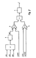
- the method according to the invention can assume three states, which are shown in FIG.
- a first state 1 the method is "inactive".
- a status variable tpmCSCSTAT has the value 0.
- the method transitions to a second state 2 when the lateral acceleration mrmAQRabs acting on the motor vehicle is greater than or equal to an associated acceleration threshold tpwCSCAY and if the engine torque mrmMOMOT is greater than or equal to a corresponding first threshold tpwCSCMOM1 is.
- the second state 2 indicates a cornering of the motor vehicle ("curve").
- the status variable tpmCSCSTAT has the value 1.
- the method returns to the first state 1 when the lateral acceleration mrmAQRabs is less than the associated acceleration threshold tpwCSCAY. Both in the first state 1 and in the second state 2 there is no change in the intervention variable in the sense of a specification of a minimum value.
- the method transitions to a third state 3 when the engine torque mrmMOMOT is smaller than or equal to the associated first threshold value tpwCSCMOM1.
- the method is "active", there is an intervention by a minimum value for the intervention size is output.
- the status variable tpmCSCSTAT has the value 2. The method exits the third state 3 and changes to the first state 1 when the engine torque mrmMOMOT is greater than or equal to a corresponding second threshold value tpwCSCMOM2.
- the procedure is from the DE 199 13 825 known, up which is expressly incorporated herein by reference.
- the predetermined minimum value of the intervention variable or the time duration, for which the drive motor is subjected to the minimum value according to the present invention as a function of corrected various driving dynamics parameters.
- FIG. 2 shows a functional diagram of a preferred embodiment of the method according to the invention.
- the determined minimum value of the intervention variable is not corrected, but the time duration t, for which the drive motor is subjected to the determined minimum value.
- a processing unit 4 In order to determine the friction coefficient MUE of the roadway, information about the activation of an anti-lock braking system ABS, traction control ASR and an engine drag torque control MSR are used. In a processing unit 4 it is determined how many times within a predeterminable time window and / or with which intensity one or more of these functions have been activated. An output MUE of the processing unit 4 is fed to a comparison unit 5, where it is compared with an associated threshold tpwMUE. If the output signal MUE is smaller than the threshold value tpwMUE, a low coefficient of friction MUE of the roadway is assumed.
- a second comparison unit 6 the delay VERZ of the motor vehicle with an associated threshold value tpwVERZ compared. If the coefficient of friction MUE of the roadway falls below the threshold value tpwMUE and / or the delay VERZ exceeds the threshold value tpwVERZ, the time duration t for which the drive motor is subjected to the minimum value of the intervention variable is extended in a delay unit 7. A corresponding functional diagram is shown in FIG.
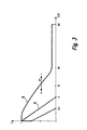
- curves of various correction values as a function of the time duration t for which the corrected minimum value of the intervention variable is applied to the drive motor are shown for different coefficients of friction MUE of a roadway.
- the duration of action t of the method according to the invention is - illustrated by a double arrow ⁇ - extended at a low coefficient of friction MUE (-) of the road (see curve 8).
- the duration of action t of the method according to the invention can be correspondingly shortened (compare curve 9).
- the duration or the frequency of the response of a low coefficient indicator MUE extends the duration of action t of the method according to the invention.
- the coefficient of friction MUE of the roadway can also be determined by evaluating the rotational speeds N of the wheels of the motor vehicle, in particular the drive wheels. Also conceivable would be an optical evaluation of the road or an acoustic evaluation of the tire noise. Finally, the friction coefficient MUE of the roadway could also be determined by means of suitable sensors incorporated in the tire walls, for example by means of strain gauges DMS.
- the determined minimum value of the intervention variable could also be raised for correction, if the friction coefficient MUE of the roadway falls below the threshold value tpwMUE and / or the delay VERZ exceeds the threshold value tpwVERZ.
- this can also be corrected as a function of further driving dynamics parameters, as shown in FIG. 4.
- a variable tpmN for the rotational speed of the drive motor and a further variable tpmAY for the lateral acceleration of the motor vehicle are fed to a map tpwCSCNAKF, on the basis of which a rotational speed and lateral acceleration-dependent minimum value tpmCSCNAKF for the intervention variable is determined.
- the minimum value tpmCSCNAKF can be corrected as a function of the absolute altitude at which the motor vehicle is located. For this purpose, an absolute value corresponding to the offset value tpmCSCSVKF is added to the minimum value tpmCSCNAKF.
- the offset value tpmCSCSVKF is final-dependent and therefore can not be applied.
- the minimum value tpmCSCNAKF can be corrected as a function of the gradient tpmSTEIG of the roadway on which the motor vehicle is traveling. For this purpose, the slope tmpSTEIG is fed to a map tpwCSCSTKL, based on which a slope-dependent correction factor tpmCSCSTKL is determined. The minimum value tpmCSCNAKF or the corrected minimum value is multiplied by the correction factor tpmCSCSTKL.
- Further correction values can be added to the minimum value tpmCSCNAKF if there is a lateral acceleration of the motor vehicle or if the speed and lateral acceleration-dependent minimum value tpmCSCNAKF is greater than 0.
- the minimum value tpmCSCNAKF is passed to a comparison unit 12, where it has the value "0". is compared.
- the output signal of the comparison unit 12 drives a switching unit 13. If the minimum value tpmCSCNAKF is less than or equal to "0", the switching unit 13 remains in the position shown in FIG. 4 and at its output is the value "0".
- the switching unit 13 switches on and the further correction values tpmCSCWTKL, tpmCSCGAKL and / or tpmCSCKIK are applied to the output of the switching unit 13.
- a variable tpmWTF for the temperature of the drive motor is fed to a further map tpwCSCWTKL, on the basis of which a temperature-dependent correction value tpmCSCWTKL is determined.
- Another map tpwCSCGAKL is supplied with a quantity tpmGANG for the engaged gear of a transmission unit of the motor vehicle.
- an aisle position-dependent correction value tpmCSCGAKL is determined, which is added to the temperature-dependent correction value tpmCSCWTKL.
- Another variable tpmFKLE contains information about whether an air conditioning compressor of the motor vehicle is in operation or not.
- the variable tpmFKLE is fed to a comparison unit 10.
- a switching unit 11 In response to an output signal of the comparison unit 10, a switching unit 11 is driven. If the air conditioning compressor is in operation, the switching unit 11 is actuated, so that at the output of the switching unit 11 is applied a consumer-dependent correction value tpmCSCKLIK. Otherwise, the switching unit 11 remains in the position shown in Fig. 4 and at the output of the switching unit 11 is "0".
- the method according to the invention becomes active if the gradient-compensated sum tpmCSCSUSK is greater than the determined value tpmESG for the setting value minus an offset tpwCSCARDO.
- the comparison takes place in a comparison unit 15. With the aid of an output signal of the comparison unit 15, a switching unit 16 is driven. As output signal, the switching unit 16 outputs either the time counter tpmCSCTIME or a value of the time counter tpmCSCTIME increased by a certain addend (+1 or +4).
- FIG. 6 shows a further functional diagram in which, in order to avoid jumps in the intervention variable, the corrected minimum value of the intervention variable is gradient-limited over a temporal ramp tpwCSCRAMP.
- a weighting factor tpmCSCTIKL is determined in a map tpwCSCTIKL as a function of the time counter tpmCSCTIME. This is usually between 0 and 3.
- the slope-compensated sum tpmCSCSUSK is multiplied by the weighting factor tpmCSCTIKL.
- the output quantity of the multiplication is a time-weighted sum tpmCSCSUTI. From the time-weighted sum tpmCSCSUTI, the gradient tpmCSCGRAD of the setting variable is calculated in a function block 19. Furthermore, a slope-limited output signal tpmCSCOUT is determined from the time-weighted sum tpmCSCSUTI by means of a characteristic diagram tpwCSCRAMP.
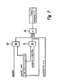
- FIG. 7 illustrates when the method according to the invention is deactivated. This is, for example, the case when a coupling dimKUP of the motor vehicle is open and no intervention by the method according to the invention is desired (AND operation 20).
- the method is also activated when the gear gangstat of the motor vehicle is in a neutral position NEUTRAL and no intervention by the inventive method is desired (AND operation 21).
- the method is deactivated when a main switch is turned off.
- the method according to the invention is also deactivated when the status variable tpmCSCSTAT # 2 is (see Fig. 1). If one of these conditions exists, the inventive method is deactivated and all outputs are reset.
Landscapes
- Engineering & Computer Science (AREA)
- Transportation (AREA)
- Mechanical Engineering (AREA)
- Combustion & Propulsion (AREA)
- Chemical & Material Sciences (AREA)
- Automation & Control Theory (AREA)
- Electric Propulsion And Braking For Vehicles (AREA)
- Control Of Vehicle Engines Or Engines For Specific Uses (AREA)
- Electrical Control Of Air Or Fuel Supplied To Internal-Combustion Engine (AREA)
- Electrical Control Of Ignition Timing (AREA)
- Control Of Throttle Valves Provided In The Intake System Or In The Exhaust System (AREA)
- Regulating Braking Force (AREA)
- Control Of Driving Devices And Active Controlling Of Vehicle (AREA)
- Combined Controls Of Internal Combustion Engines (AREA)
Abstract
Claims (23)
- Procédé pour influencer un couple fourni par un moteur d'entraînement de véhicule (mrmMOMOT), selon lequel :- on calcule un changement de charge se produisant lorsque le véhicule est dans un virage ;- si pendant un virage un changement de charge intervient, on calcule une valeur minimale (tpmCSCNAKF) d'une grandeur d'intervention influençant le couple fourni (mrmMOMOT) ; et- on charge le moteur d'entraînement avec la valeur minimale (tpmCSCNAKF) de la grandeur d'intervention pour une durée donnée (t),caractérisé en ce que
on corrige la valeur minimale calculée (tpmCSCNAKF) de la grandeur d'intervention et/ ou la durée (t), en fonction du coefficient de friction (MUE) de la chaussée sur laquelle roule le véhicule, et/ou en fonction d'une décélération (VERZ) du véhicule. - Procédé selon la revendication 2,
caractérisé en ce qu'
on augmente la valeur minimale calculée (tpmCSCNAKF) de la grandeur d'intervention si le coefficient de friction (MUE) de la chaussée est inférieur à une première valeur seuil donnée (tpwMUE) et/ou si la décélération (VERZ) du véhicule est supérieure à une deuxième valeur seuil donnée (tpwVERZ). - Procédé selon la revendication 1 ou 2,
caractérisé en ce que
on charge le moteur d'entraînement avec la valeur minimale (tpmCSCNAKF) de la grandeur d'intervention pour une durée (t) prolongée si le coefficient de friction (MUE) de la chaussée est inférieur à une première valeur seuil donnée (tpwMUE) et/ou si la décélération (VERZ) du véhicule est supérieure à une deuxième valeur seuil (tpwVERZ) donnée. - Procédé selon l'une quelconque des revendications 1 à 3,
caractérisé en ce que
on calcule la valeur minimale (tpmCSCNAKF) de la grandeur d'intervention à partir de deux valeurs,- une première valeur calculée en fonction de la vitesse de rotation (tpmN) du moteur d'entraînement et d'une accélération transversale (tpmAY) du véhicule ;- une deuxième valeur calculée en fonction d'un glissement d'au moins l'une des roues du véhicule et d'une vitesse du véhicule ; etla valeur minimale (tpmCSCNAKF) est calculée à partir de la somme de la première et de la deuxième valeur. - Procédé selon la revendication 4,
caractérisé en ce que
on calcule la valeur minimale (tpmCSCNAKF) de la grandeur d'intervention en fonction de deux champs caractéristiques, la première valeur étant calculée à l'aide d'un premier champ caractéristique (tpwCSCNAKF) et la deuxième valeur à l'aide d'un deuxième champ caractéristique. - Procédé selon l'une quelconque des revendications 1 à 5,
caractérisé en ce que
on corrige la valeur minimale calculée (tpmCSCNAKF) de la grandeur d'intervention en fonction d'une pente (tpmSTEIG) d'une chaussée sur laquelle roule le véhicule et/ou en fonction d'une hauteur absolue (tpmCSCVKF) à laquelle se trouve le véhicule, et on charge le moteur d'entraînement avec la valeur minimale corrigée (tpmCSCSUMM ; tpmCSCSUSK). - Procédé selon la revendication 6,
caractérisé en ce que
pour la correction, on multiplie la valeur minimale calculée (tpmCSCNAKF) de la grandeur d'intervention avec un facteur de correction (tpmCSCSTKL) qui est fonction de la pente et/ ou de la hauteur. - Procédé selon la revendication 7,
caractérisé en ce qu'
on calcule le facteur de correction (tpmCSCSTKL) à l'aide d'un troisième champ caractéristique (tpwCSCSTKL). - Procédé selon l'une quelconque des revendications 1 à 8,
caractérisé en ce que
on corrige la valeur minimale calculée (tpmCSCNAKF) de la grandeur d'intervention en fonction de la température (tpmWTF) du moteur d'entraînement s'il s'opère une accélération transversale du véhicule, et on charge le moteur d'entraînement avec la valeur minimale corrigée (tpmCSCSUMM ; tpmCSCSUSK). - Procédé selon l'une quelconque des revendications 1 à 9,
caractérisé en ce que
on corrige la valeur minimale calculée (tpmCSCNAKF) de la grandeur d'intervention en fonction de la position d'une boîte de vitesse (tpmGANG) du véhicule s'il s'opère une accélération transversale du véhicule, et on charge le moteur d'entraînement avec une valeur minimale corrigée (tpmCSCSUMM ; tpmCSCSUSK). - Procédé selon l'une quelconque des revendications 1 à 10,
caractérisé en ce qu'
on corrige la valeur minimale calculée (tpmCSCNAKF) de la grandeur d'intervention en fonction du type et du nombre de récepteurs (tpmFKLE) en fonctionnement compris dans le véhicule s'il s'opère une accélération transversale du véhicule, et on charge le moteur avec la valeur minimale corrigée (tpmCSCSUMM ; tpmCSCSUSK). - Procédé selon l'une quelconque des revendications 8 à 11,
caractérisé en ce qu'
on ajoute une valeur de correction (tpmCSCKLIK) qui est fonction des récepteurs et/ou de la position de la boîte de vitesse (tpmCSCGAKL) et/ ou de la température du moteur (tpmCSCWTKL) à la valeur minimale calculée (tpmCSCNAKF) de la grandeur d'intervention. - Procédé selon l'une quelconque des revendications 1 à 12,
caractérisé en ce que
pour calculer un changement de charge, on exploite la position d'une pédale d'accélérateur du véhicule ou le couple (mrmMOMOT) fourni par le moteur d'entraînement. - Procédé selon l'une quelconque des revendications 1 à 13
caractérisé en ce qu'
une quantité de carburant à injecter sert de grandeur d'intervention influençant le couple fourni (mrmMOMOT) dans le cas d'un moteur d'entraînement conçu en tant que moteur à combustion interne. - Procédé selon l'une quelconque des revendications 1 à 14,
caractérisé en ce qu'
un moment d'injection du carburant sert de grandeur d'intervention influençant le couple fourni (mrmMOMOT) dans le cas d'un moteur d'entraînement conçu en tant que moteur à combustion interne. - Procédé selon l'une quelconque des revendications 1 à 15,
caractérisé en ce qu'
un point d'allumage d'un mélange carburant/ air sert de grandeur d'intervention influençant le couple fourni (mrmMOMOT) dans le cas d'un moteur d'entraînement conçu en tant que moteur à combustion interne. - Procédé selon l'une quelconque des revendications 1 à 13 ou 16,
caractérisé en ce qu'
un angle d'un papillon des gaz du moteur à combustion interne sert de grandeur d'intervention influençant le couple fourni (mrmMOMOT) dans le cas d'un moteur d'entraînement conçu en tant que moteur à combustion interne. - Procédé selon l'une quelconque des revendications 1 à 13,
caractérisé en ce qu'
un courant ou une tension d'un moteur d'entraînement conçu sous forme de moteur électrique sert de grandeur d'intervention influençant le couple fourni (mrmMOMOT). - Appareil de commande pour un contrôle dynamique de trajectoire d'un véhicule, capable de :- calculer un changement de charge intervenant lorsque le véhicule est dans un virage ;- calculer une valeur minimale (tpmCSCNAKF) d'une grandeur d'intervention influençant le couple fourni (mrmMOMOT) par un moteur d'entraînement du véhicule si un changement de charge intervient pendant un virage ; et- charger le moteur d'entraînement avec la valeur minimale (tpmCSCNAKF) de la grandeur d'intervention pour une durée donnée (t),caractérisé en ce qu'
il corrige la valeur minimale calculée (tpmCSCNAKF) de la grandeur d'intervention et/ou la durée (t) en fonction du coefficient de friction (MUE) d'une chaussée sur laquelle roule le véhicule, et/ou en fonction d'une décélération (VERZ) du véhicule. - Appareil de commande selon la revendication 19,
caractérisé en ce qu'
il comporte des moyens de réalisation d'un procédé selon l'une quelconque des revendications 2 à 18. - Elément de mémoire, notamment mémoire morte, mémoire vive ou mémoire flash, pour un appareil de contrôle dynamique de trajectoire d'un véhicule, sur lequel on a enregistré un programme informatique pouvant être lu par un ordinateur, notamment un microprocesseur, et programmé pour réaliser un procédé selon l'une quelconque des revendications 1 à 18.
- Programme informatique,
caractérisé en ce que
le programme informatique convient à la réalisation d'un procédé selon l'une quelconque des revendications 1 à 18, lorsqu'il est lu par un ordinateur, notamment par un microprocesseur. - Programme informatique selon la revendication 22,
caractérisé en ce que
il est enregistré sur un élément de mémoire, notamment sur une mémoire flash.
Applications Claiming Priority (3)
| Application Number | Priority Date | Filing Date | Title |
|---|---|---|---|
| DE19958392 | 1999-12-03 | ||
| DE19958392 | 1999-12-03 | ||
| PCT/EP2000/012163 WO2001040041A1 (fr) | 1999-12-03 | 2000-12-04 | Procede pour influencer un couple fourni par un moteur d'entrainement d'un vehicule |
Publications (2)
| Publication Number | Publication Date |
|---|---|
| EP1165352A1 EP1165352A1 (fr) | 2002-01-02 |
| EP1165352B1 true EP1165352B1 (fr) | 2007-07-04 |
Family
ID=7931349
Family Applications (1)
| Application Number | Title | Priority Date | Filing Date |
|---|---|---|---|
| EP00990637A Expired - Lifetime EP1165352B1 (fr) | 1999-12-03 | 2000-12-04 | Procede pour influencer un couple fourni par un moteur d'entrainement d'un vehicule |
Country Status (6)
| Country | Link |
|---|---|
| US (1) | US6611747B1 (fr) |
| EP (1) | EP1165352B1 (fr) |
| JP (1) | JP2004500507A (fr) |
| KR (1) | KR20010094753A (fr) |
| DE (2) | DE10060347A1 (fr) |
| WO (1) | WO2001040041A1 (fr) |
Families Citing this family (14)
| Publication number | Priority date | Publication date | Assignee | Title |
|---|---|---|---|---|
| DE10238464B4 (de) | 2002-03-26 | 2020-07-09 | Robert Bosch Gmbh | Erkennung des Kupplungszustandes während einer Motorschleppmomentenregelung |
| DE10238224B4 (de) * | 2002-03-27 | 2014-09-11 | Robert Bosch Gmbh | Kurvenabhängige Motorschleppmomentenregelung |
| DE10221341B4 (de) * | 2002-05-08 | 2015-03-26 | Robert Bosch Gmbh | Verfahren und Vorrichtung zur Steuerung der Antriebseinheit eines Fahrzeuges |
| WO2005042321A1 (fr) * | 2003-10-28 | 2005-05-12 | Continental Teves Ag & Co.Ohg | Procede et systeme permettant d'ameliorer le comportement routier d'un vehicule |
| FR2866283B1 (fr) * | 2004-01-14 | 2006-09-22 | Bosch Gmbh Robert | Procede et dispositif de gestion d'une unite d'entrainement d'un vehicule |
| JP4640224B2 (ja) * | 2006-03-15 | 2011-03-02 | 日産自動車株式会社 | 車両走行路の湾曲傾向検出装置およびこれを用いた車両の動作応答制御装置 |
| KR101225536B1 (ko) * | 2006-09-07 | 2013-01-23 | 주식회사 만도 | 4륜 구동 차량의 차량안전 시스템 제어방법 |
| US7990263B2 (en) * | 2006-09-28 | 2011-08-02 | Beatty Street Properties, Inc. | Vector-based harbor scheduling |
| DE102006052106A1 (de) * | 2006-11-04 | 2008-05-21 | Zf Friedrichshafen Ag | Verfahren zum fahrstreckenneigungsabhängigen Steuern und/oder Regeln eines Automatgetriebes eines Fahrzeuges |
| US9475388B2 (en) | 2008-05-14 | 2016-10-25 | GM Global Technology Operations LLC | Drag torque request security diagnostic systems and methods |
| DE102008001973A1 (de) * | 2008-05-26 | 2009-12-03 | Robert Bosch Gmbh | Verfahren zum Regeln eines Schleppmomentes eines elektromotorisch angetriebenen Kraftfahrzeuges unter Berücksichtigung des auf der Fahrbahnoberfläche vorliegenden Reibwertes und Vorrichtung zum Durchführen eines solchen Verfahrens |
| JP5336447B2 (ja) * | 2010-09-02 | 2013-11-06 | 日立建機株式会社 | 電気駆動車両 |
| DE102015223504A1 (de) * | 2015-11-27 | 2017-06-01 | Robert Bosch Gmbh | Verfahren und Vorrichtung zum Betreiben eines Kraftfahrzeugs |
| KR102297408B1 (ko) | 2017-04-06 | 2021-09-03 | 현대자동차주식회사 | 차량 및 그 제어 방법 |
Family Cites Families (9)
| Publication number | Priority date | Publication date | Assignee | Title |
|---|---|---|---|---|
| DE3808692A1 (de) | 1988-03-16 | 1989-10-05 | Bosch Gmbh Robert | Verfahren zur vermeidung eines zu grossen motorschleppmoments |
| JP2621084B2 (ja) * | 1988-08-02 | 1997-06-18 | 本田技研工業株式会社 | アイドル回転数制御装置 |
| DE3942862C2 (de) * | 1989-12-23 | 2001-04-12 | Bosch Gmbh Robert | Verfahren zur Motorschleppmomentbegrenzung |
| DE19532528A1 (de) * | 1995-09-02 | 1997-03-06 | Porsche Ag | Verfahren und Vorrichtung zur Verminderung der Lastwechselreaktion eines Kraftfahrzeuges bei Kurvenfahrt |
| DE19547717B4 (de) | 1995-12-20 | 2006-07-13 | Robert Bosch Gmbh | Verfahren und Vorrichtung zur Abschwächung von Lastwechselreaktionen bei einem Kraftfahrzeug |
| DE19607185A1 (de) * | 1996-02-27 | 1997-08-28 | Bayerische Motoren Werke Ag | Verfahren zur Sicherstellung eines neutralen Fahrverhaltens bei Kurvenfahrten und gleichzeitigem Lastwechsel |
| JP3272617B2 (ja) * | 1996-11-13 | 2002-04-08 | 本田技研工業株式会社 | 車両のヨーモーメント制御装置 |
| DE19844912A1 (de) | 1998-09-30 | 2000-04-13 | Bosch Gmbh Robert | Vorrichtung und Verfahren zur Beeinflussung des Vortriebes eines Fahrzeuges |
| DE19913825A1 (de) | 1999-03-26 | 2000-09-28 | Bosch Gmbh Robert | Regelsystem für ein Fahrzeug |
-
2000
- 2000-12-04 EP EP00990637A patent/EP1165352B1/fr not_active Expired - Lifetime
- 2000-12-04 DE DE2000160347 patent/DE10060347A1/de not_active Withdrawn
- 2000-12-04 US US09/889,836 patent/US6611747B1/en not_active Expired - Fee Related
- 2000-12-04 KR KR1020017009730A patent/KR20010094753A/ko not_active Application Discontinuation
- 2000-12-04 WO PCT/EP2000/012163 patent/WO2001040041A1/fr active IP Right Grant
- 2000-12-04 DE DE50014455T patent/DE50014455D1/de not_active Expired - Lifetime
- 2000-12-04 JP JP2001541746A patent/JP2004500507A/ja not_active Withdrawn
Non-Patent Citations (1)
| Title |
|---|
| None * |
Also Published As
| Publication number | Publication date |
|---|---|
| WO2001040041A1 (fr) | 2001-06-07 |
| DE50014455D1 (de) | 2007-08-16 |
| EP1165352A1 (fr) | 2002-01-02 |
| KR20010094753A (ko) | 2001-11-01 |
| JP2004500507A (ja) | 2004-01-08 |
| DE10060347A1 (de) | 2001-08-09 |
| WO2001040041A9 (fr) | 2002-09-12 |
| US6611747B1 (en) | 2003-08-26 |
Similar Documents
| Publication | Publication Date | Title |
|---|---|---|
| DE102016013126B4 (de) | Vorrichtung zur Steuerung von Fahrzeugverhalten | |
| DE3807757C2 (fr) | ||
| EP0739465B1 (fr) | Commande pour boite de vitesses automatique d'automobile | |
| EP1165352B1 (fr) | Procede pour influencer un couple fourni par un moteur d'entrainement d'un vehicule | |
| EP2327596B1 (fr) | Limitation appuyée par la valeur de friction du couple d'un circuit de réglage d'un véhicule automobile | |
| DE102018121458B4 (de) | Vorrichtung zur steuerung von fahrzeugantriebskraft | |
| EP1123475B1 (fr) | Procede de commande d'une boite automatique d'un vehicule automobile lors d'un relachement spontane de l'accelerateur | |
| DE3831105C1 (fr) | ||
| DE102011083332A1 (de) | Verfahren und Vorrichtung zum automatischen Aktivieren bzw. Deaktivieren einer Segel-Betriebsart bei einem Kraftfahrzeug mit Verbrennungsmotor | |
| DE69122110T2 (de) | Beschleunigungsschlupfregelvorrichtung für fahrzeuge | |
| EP1475265B1 (fr) | Procédé de commande d'un véhicule | |
| DE102016013123A1 (de) | Vorrichtung zur Steuerung von Fahrzeugverhalten | |
| DE102019201432A1 (de) | Fahrzeug-Steuervorrichtung | |
| DE19913824B4 (de) | Verfahren und Vorrichtung zur Steuerung einer Antriebseinheit | |
| EP3019376B1 (fr) | Procédé et dispositif de régulation automatique d'une dynamique longitudinale d'un véhicule à moteur | |
| DE69219489T2 (de) | Traktionssteuersystem für Motorfahrzeuge | |
| DE19844542A1 (de) | Vorrichtung und Verfahren zum Begrenzen einer Rückrollgeschwindigkeit eines Kraftfahrzeuges | |
| DE69301298T2 (de) | Momentenkontrollsystem für die Antriebsräder eines Kraftfahrzeuges | |
| EP0780275B1 (fr) | Méthode et dispositif pour régulation de patinage | |
| EP1826082B1 (fr) | Système de réglage de patinage et procédé destiné au réglage de mouvements de roues d'un véhicule | |
| EP1912838B1 (fr) | Procede de commande de freins continus d'un vehicule a moteur | |
| DE3644136C1 (de) | Einrichtung zur Vortriebsregelung an Kraftfahrzeugen | |
| EP1152914B1 (fr) | Procede et unite de commande pour dispositif influencant la propulsion d'un vehicule | |
| DE4028809A1 (de) | System zur steuerung eines kraftfahrzeugs | |
| EP1192069A1 (fr) | Procede et dispositif de regulation antipatinage |
Legal Events
| Date | Code | Title | Description |
|---|---|---|---|
| PUAI | Public reference made under article 153(3) epc to a published international application that has entered the european phase |
Free format text: ORIGINAL CODE: 0009012 |
|
| AK | Designated contracting states |
Kind code of ref document: A1 Designated state(s): AT BE CH CY DE DK ES FI FR GB GR IE IT LI LU MC NL PT SE TR |
|
| 17P | Request for examination filed |
Effective date: 20011207 |
|
| RBV | Designated contracting states (corrected) |
Designated state(s): DE FR GB |
|
| GRAP | Despatch of communication of intention to grant a patent |
Free format text: ORIGINAL CODE: EPIDOSNIGR1 |
|
| RIC1 | Information provided on ipc code assigned before grant |
Ipc: B60W 30/18 20060101ALI20061219BHEP Ipc: B60W 30/02 20060101AFI20061219BHEP |
|
| GRAS | Grant fee paid |
Free format text: ORIGINAL CODE: EPIDOSNIGR3 |
|
| GRAA | (expected) grant |
Free format text: ORIGINAL CODE: 0009210 |
|
| AK | Designated contracting states |
Kind code of ref document: B1 Designated state(s): DE FR GB |
|
| REG | Reference to a national code |
Ref country code: GB Ref legal event code: FG4D Free format text: NOT ENGLISH |
|
| REF | Corresponds to: |
Ref document number: 50014455 Country of ref document: DE Date of ref document: 20070816 Kind code of ref document: P |
|
| GBV | Gb: ep patent (uk) treated as always having been void in accordance with gb section 77(7)/1977 [no translation filed] |
Effective date: 20070704 |
|
| EN | Fr: translation not filed | ||
| PLBE | No opposition filed within time limit |
Free format text: ORIGINAL CODE: 0009261 |
|
| STAA | Information on the status of an ep patent application or granted ep patent |
Free format text: STATUS: NO OPPOSITION FILED WITHIN TIME LIMIT |
|
| PG25 | Lapsed in a contracting state [announced via postgrant information from national office to epo] |
Ref country code: GB Free format text: LAPSE BECAUSE OF FAILURE TO SUBMIT A TRANSLATION OF THE DESCRIPTION OR TO PAY THE FEE WITHIN THE PRESCRIBED TIME-LIMIT Effective date: 20070704 |
|
| 26N | No opposition filed |
Effective date: 20080407 |
|
| PG25 | Lapsed in a contracting state [announced via postgrant information from national office to epo] |
Ref country code: FR Free format text: LAPSE BECAUSE OF FAILURE TO SUBMIT A TRANSLATION OF THE DESCRIPTION OR TO PAY THE FEE WITHIN THE PRESCRIBED TIME-LIMIT Effective date: 20080229 |
|
| PGFP | Annual fee paid to national office [announced via postgrant information from national office to epo] |
Ref country code: DE Payment date: 20200221 Year of fee payment: 20 |
|
| REG | Reference to a national code |
Ref country code: DE Ref legal event code: R071 Ref document number: 50014455 Country of ref document: DE |