EP1165318B1 - Support de mandrin pour appareils de decoration de boites metalliques fonctionnant a grande vitesse - Google Patents
Support de mandrin pour appareils de decoration de boites metalliques fonctionnant a grande vitesse Download PDFInfo
- Publication number
- EP1165318B1 EP1165318B1 EP00913327A EP00913327A EP1165318B1 EP 1165318 B1 EP1165318 B1 EP 1165318B1 EP 00913327 A EP00913327 A EP 00913327A EP 00913327 A EP00913327 A EP 00913327A EP 1165318 B1 EP1165318 B1 EP 1165318B1
- Authority
- EP
- European Patent Office
- Prior art keywords
- carrier
- mandrel
- axle
- decorating
- axis
- Prior art date
- Legal status (The legal status is an assumption and is not a legal conclusion. Google has not performed a legal analysis and makes no representation as to the accuracy of the status listed.)
- Expired - Lifetime
Links
Images


Classifications
-
- B—PERFORMING OPERATIONS; TRANSPORTING
- B41—PRINTING; LINING MACHINES; TYPEWRITERS; STAMPS
- B41F—PRINTING MACHINES OR PRESSES
- B41F17/00—Printing apparatus or machines of special types or for particular purposes, not otherwise provided for
-
- B—PERFORMING OPERATIONS; TRANSPORTING
- B41—PRINTING; LINING MACHINES; TYPEWRITERS; STAMPS
- B41F—PRINTING MACHINES OR PRESSES
- B41F17/00—Printing apparatus or machines of special types or for particular purposes, not otherwise provided for
- B41F17/08—Printing apparatus or machines of special types or for particular purposes, not otherwise provided for for printing on filamentary or elongated articles, or on articles with cylindrical surfaces
- B41F17/14—Printing apparatus or machines of special types or for particular purposes, not otherwise provided for for printing on filamentary or elongated articles, or on articles with cylindrical surfaces on articles of finite length
- B41F17/20—Printing apparatus or machines of special types or for particular purposes, not otherwise provided for for printing on filamentary or elongated articles, or on articles with cylindrical surfaces on articles of finite length on articles of uniform cross-section, e.g. pencils, rulers, resistors
- B41F17/22—Printing apparatus or machines of special types or for particular purposes, not otherwise provided for for printing on filamentary or elongated articles, or on articles with cylindrical surfaces on articles of finite length on articles of uniform cross-section, e.g. pencils, rulers, resistors by rolling contact
Definitions
- This invention relates generally to continuous motion high speed apparatus for applying decorations to cylindrical containers and in particular relates to improvements in mandrel carriers for apparatus of that type which is disclosed in U.S. Patents Nos. 4,821,638 , 5,799,574 , U.S. Patent No. 3,766,851 , U.S. Patent No. 4,140,053 , and U.S. Patent No. 5,111,742 ,
- U.S. Patent No. 5,799,574 discloses relatively high speed apparatus for applying decorations to the exterior of cylindrical containers while they are mounted on mandrels which are disposed along the periphery of a large continuously rotating disc-like carrier. Decorations are applied to the containers as they engage a rotating blanket of a decorator that is adjacent the periphery of the carrier. During engagement between the containers and the blanket, the containers track the blanket surface through the printing region where the containers and blanket surface are engaged. To accomplish this tracking, for each angular position of the container measured about the axis of the spindle disc as a center, a device controlled by a closed loop or box cam maintains the container in a precise radial position relative to the axis of the spindle disc.
- This type of decorating equipment includes a number of relatively heavy elements that move at high speed. Because there must be precise coordination between the various elements, inertia forces, lubrication and operating power are significant engineering design considerations, as are equipment downtime, maintenance costs and setup procedures.
- US 5,572,927 discloses an apparatus for decorating cylindrical articles including a plurality of mandrel assemblies mounted on a carrier that rotates continuously on a main axis. Subassembly tilting is inhibited through sliding engagement of a follower (roller) on the subassembly with a brace or track on the rotating carrier. Cooperation between the follower and the brace also acts to limit deflection of the cantilevered mandrel relative to the carrier.
- a follower roller
- Cooperation between the follower and the brace also acts to limit deflection of the cantilevered mandrel relative to the carrier.
- US 4,498,387 discloses a mandrel assembly for use in a machine for continuous printing of cylindrical containers, comprising a mandrel wheel and mandrel holders, which are pivotally mounted on circumferential portions of the mandrel wheel.
- each of the mandrels is part of an individual mandrel subassembly that includes a support arm which must be relatively rigid in order to properly position the cantilevered mandrel while decorations are being applied to the container carried thereby.
- the arm is relatively flat and is provided with a longitudinally extending rail that rides in a linear slide which directs the subassembly to reciprocate radially with respect to the rotational axis of the mandrel carrier.
- Sideways deflection of the subassembly arm relative to the mandrel carrier is limited by utilizing a roller type linear slide which has multiple groups of bearing elements that engage longitudinal bearing surfaces on the rail. Each bearing surface faces in a different direction and is engaged by a different group of bearing elements.
- Each bearing element is cylindrical and has a rotational axes that is transverse to the reciprocation path of the rail that is engaged by such element.
- Positional integrity of the subassemblies relative to the carrier is maintained by providing shallow channels in the carrier to receive the slides, and shallow grooves in the support arms to receive an individual rail.
- Parallel channel arms fit tightly against the housing for the slide that is entered in the channel and arms forming the groove fit tightly against side surfaces of the rail.
- the axis of the spindle is eccentric with respect to the axis of the rear mounting section of the axle having the spindle at the front thereof.
- the mounting section is provided with an external cylindrical surface that is engaged by a matching internal cylindrical surface of a mounting hole in the subassembly arm at the radially outer end thereof.
- Pivoting of the axle is accomplished by two adjusting screws, each of which is on the arm and extends inward of the internal cylindrical surface of the internal cylindrical surface to engage an individual ledge formed in the external cylindrical surface.
- the primary object of the instant invention is to provide an improved high speed continuous motion cylindrical container decorator having substantially reduced maintenance and/or power requirements.
- Another object is to provide a decorator of this type wherein substantial cost and weight reductions have been achieved for the disc-like carrier and reciprocating mandrel subassemblies carried thereby.
- Still another object is to provide a construction for this type of decorator to simplify setup procedures, extend periods of operation and reduce downtime for maintenance.
- a further object is to reduce printing pressure requirements while maintaining print quality.
- a still further object is to improve positional integrity between the mandrel carrier and moving elements of the mandrel subassemblies mounted on the carrier and reciprocating radially with respect to the rotational axis of the carrier.
- Yet another object is to provide elongated roller-type linear slides to mount the reciprocating mandrel subassemblies on the carrier.
- Fig. 1 illustrates continuous motion cylindrical container decorating apparatus of the general type described in the aforesaid U.S. Patents Nos. 3,766,851 and 5,111,742 .
- the apparatus of Fig. 1 includes infeed conveyor chute 15 which receives undecorated containers in the form of beverage cans 16, each open at one end thereof, from a can supply (not shown) and places cans 16 in arcuate cradles or pockets 17 formed by aligned depressions in the outer edges of spaced segmented rings 31, 32 ( Fig. 2 ).
- the latter are Fixedly secured to support ring 33 that is positioned in front of and secured to disc-like mandrel carrier 18 on eight angularly spaced standoffs 48. Screws 43 secure the segments of pocket rings 31, 32 to support ring 33.
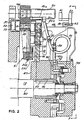
- Carrier 18 is mounted on continuously rotating horizontal drive shaft 19 whose first end (toward the left in Fig. 2 ) is rotatably supported on a fixed portion of the frame of the decorating apparatus illustrated in Fig. 1 .
- Shaft 19 is drivingly connected to carrier 18 by key 45 that engages tapered sleeve 46 which is wedged between drive shaft 19 and hub 47. The latter is welded to carrier 18 at the center thereof.
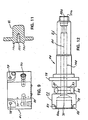
- Horizontally extending mandrels 20 are also mounted to carrier 18, with each mandrel 20 being in spaced horizontal alignment with an individual pocket 17 while passing through a short loading region extending downstream from infeed conveyor 15. In this short region, undecorated cans 16 are moved horizontally rearward by a deflector (not shown), being transferred from each cradle 17 to an individual mandrel 20. Suction applied through an axial passage 148 ( Fig. 12 ) extending to the outboard or front end 21a of spindle shaft 21 on which mandrel 20 rotates freely, draws container 16 rearward (to the left with respect to Fig. 2 ) to final seating position on mandrel 20.
- cans 16 While mounted on mandrels 20, cans 16 are decorated by being brought into engagement with continuously rotating image transfer mat or printing blanket 91 of the multicolored printing press decorating section indicated generally by reference numeral 222. Thereafter, and while mounted to mandrels 20, each decorated can 16 is coated with a protective film of varnish applied thereto by engagement with the periphery of applicator roll 23 in the overvarnish unit indicated generally by numeral 24. Cans 16 with decorations and protective coatings thereon are then transferred from spindles 20 to suction cups (not shown) mounted near the periphery of transfer wheel 27 while the latter rotates about shaft 28 as a center. Cans 16 carried by transfer wheel 27 are deposited on generally horizontal pins 29 which project from chain type output conveyor 30 that carries cans 16 through a curing oven (not shown).
- each mandrel 20 should be properly loaded with a can 16. If sensor 133 detects that a mandrel 20 is unloaded or is not properly loaded, then before this particular mandrel 20 enters the decorating zone wherein printing blanket 91 normally engages can 16 on mandrel 20, this unloaded or misloaded mandrel 20 is moved to a tripped or "no-print" position relative to printing blanket 91. As a tripped mandrel 20 moves through the decorating zone it will be spaced from the periphery of blanket 91.
- This no-print position is achieved by controlling double acting cylinder 34 to trip subframe 35 having mandrel carrier shaft 19 mounted thereon, by moving subframe 35 to the left with respect to Fig. 1 while main base 36, to which printing unit 22 is mounted, remains stationary. Further, actuation of sensor 133 causes overvarnish unit 24 to move downward with respect to mandrel carrying shaft 19 so that the tripped spindles 20 do not engage overvarnish application roll 23.
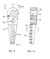
- Mandrel 20 is part of mandrel subassembly 40 that also includes support arm or base 41 ( Fig. 8 ), shaft 44 ( Fig. 12 ), rigid straight rail 51 and two cam follower rollers 57, 58.
- Spindle 21 is the front portion of shaft 44 and extends forward from arm 41 near its radially outer end, being perpendicular thereto and parallel to carrier shaft 19.
- Follower rollers 57, 58 are at the rear of arm 41, being rotatably mounted on stub shaft 61 that projects from aperture 59 which extends through arm 41 radially inward of shaft 44.
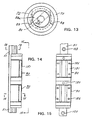
- Closed loop cam track 55 surrounds mandrel disc drive shaft 19 and receives followers 57, 58. In a manner known to the art, cooperation of cam 55 and followers 57, 58 controls the radial spacings between the respective rotational axes 80, 85 defined by shaft 19 and spindles 21, respectively.
- support arm 41 is an elongated member that is tapered lengthwise, being widest at its radially outer end where stub shaft 44 and cam follower rollers 57, 58 are mounted.
- Aperture 71 in arm 41 is disposed radially outward of aperture 59 and is provided to receive mounting section 22 ( Fig. 12 ) at the rear end of shaft 44.
- the outer cylindrical surface 72 of shaft 44 to the rear of axle shoulder 73 is closely fitted to the inner cylindrical surface of aperture 71.
- shaft 44 is pivotable relative to arm 41 about the axis 74 about which surface 72 is formed.
- Pressurized air and vacuum are selectively supplied to aperture 71 through L-shaped passage 81 whose outer end is connected through rigid stub pipes 82a, 82b to fitting 82 ( Fig. 2 ) at one end of flexible hose 83.
- the inner end of passage 81 communicates with circular undercut 86 in mounting surface 72 of shaft 44 and transverse passages 87, 87 connect undercut 86 with passage 148 that extends axially through shaft 44 so that pressurized air and vacuum can be present at the forward end of spindle 21.
- the end of hose 83 remote from fitting 82 is provided with fitting 84 that is connected through rigid stub pipe 85a to supply passage 85bwhich extends through movable face valve member 75 that is connected to hub 47 for continuous rotation therewith.
- Each airway between a passage 85b and the outer end of a passage 81 consists of flexible hose 83 and rigid stub pipes 82a, 82b, 85a.
- the vast majority of the length of hose 83 is bent to form a single loop with very short portions of hose 83 being required to connect such single loop to pipes 85a and 82a, 82b.
- the hose 83 is positioned so that side portions thereof do not rub against other side portions thereof or rub against other elements of the apparatus. Hose life is shortened very quickly in the event hose 83 rubs against another element or portions of the hose rub against each other.
- longitudinal passage 148 is enlarged and is provided with an internal thread that is engaged by retainer 188 which draws shoulder 73 against the front end of arm 41 to secure axle 44 to arm 41.
- longitudinal passage 148 is threaded internally to receive a screw (not shown) that retains mandrel 20 mounted on spindle shaft 21.
- Threaded apertures 78, 79 extend outward from aperture 71 and are positioned so that adjusting screws 76, 77 which extend through respective apertures 78, 79 are accessible for operation from outside of arm 41 to adjust the angular position of axle 44. That is, when screws 76, 77 move inward through apertures 78, 79 the inner ends of screws 76, 77 engage respective ledges 88, 89 in surface 72. To pivot axle 44, say clockwise when looking at its front or spindle end, screw 76 must be backed away from ledge 88 and then screw 77 is turned inward against ledge 89 until axle 44 reaches a desired angular position by turning clockwise about mounting axis 74.
- the latter axis is parallel to but slightly eccentric with respect to spindle axis 85 so that as axle 44 pivots the spacing between spindle axis 85 and axis 80 of mandrel carrier 18 changes.
- screw 76 is turned inward against ledge 88 to lock axle 44 against pivoting about mounting axis 74.
- screw 77 is backed away from ledge 89, then screw 76 is turned inward against ledge 88 to pivot axle 44 counterclockwise until spindle 21 reaches its required position, and then screw 77 is moved forward against ledge 79 to lock axle 44 against pivoting.
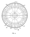
- carrier 18 is a steel disc that carries twenty-four (24) mandrel subassemblies 40 that are in a generally circular array about carrier axis 80 as a center.
- the major portion of each subassembly is arranged to reciprocate radially with respect to axis 80, being guided by the cooperation of mono rail 51 and a pair of aligned cylindrical roller-type bearing units or linear slides 90, 90 through which rail 51 extends.
- a suitable mono rail structure for the decorating apparatus of the instant invention is marketed by Schneeberger Inc., having a place of business located in Bedford, MA 01730 USA.
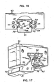
- Rail 51 ( Figs. 16 and 17 ) of such mono rail structure is an elongated member which includes rear wall 91 and short parallel sidewall sections 92, 92 extending forward from opposite ends of rear wall 91. Located at each side of rail 51 and extending forward from each wall section 92 are a pair of flat longitudinal guide surfaces 93, 93. Bearing elements 95 of two slides 90 ride on each surface 93. The pair of guide surfaces 93, 93 on the right of Fig. 16 are at right angles to each other and the rear one of this pair is at 45° with respect to right wall section 92. Similarly, the pair of guide surfaces 93, 93 on the left in Fig. 16 are mirror images of the other pair 93, 93.
- slides 90, 90 lock rail 51 from pivoting clockwise or counterclockwise about the longitudinal axis of rail 51.
- Each linear slide 90 includes four arrays 94 of bearing elements 95, one for each rail surface 93, with each bearing array being disposed to move along an individual raceway (not shown) which is formed in housing 180 of slide unit 90 so that, as seen in Fig. 17 , a portion of each array is exposed to engage a rail surface 93.
- retainer 201 ( Fig. 3 ) is removably secured to the radially inner end of arm 41 to prevent separation between rail 51 of subassembly 40 and slides 90, 90. That is, there will be interference between slides 90, 90 and retainer 201 so long as screw 202 secures retainer 201 in its operative position at the radially inner end of rail 51.
- the enlarged radially outer end of arm 41 blocks removal of slides 90, 90 at the radially outer end of rail 51.
- Arm 41 also includes shallow longitudinal channel 102 ( Fig. 11 ) defined by a pair of short parallel arms 101, 101 at the front of arm 41.
- the short sidewalls 92, 92 of rail 51 enter channel 102 and are fitted tightly between arms 101, 101 which block guide rail 51 from movement about axes that extend at right angles to rear wall 91.
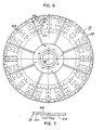
- carrier 18 is a steel disk having flat front surface 128 and rear surface 129 that is machined to form an individual shallow radial groove 125 for the pair of slides 90, 90 that guides each of the subassemblies 40.
- carrier 18 is provided with eight clearance apertures 126 that are aligned with the respective threaded apertures 136 at the front of slides 90, 90 to threadably receive fastening screws (not shown) that extend through apertures 126.
- carrier 18 is also provided with a pair of clearance apertures 127 that are aligned with respective openings 137 at the front of slides 90, 90.
- Lubricant applied through apertures 127 to openings 137 lubricates the elongated bearing elements 140 of slides 90, 90.
- Threaded mounting apertures 136 are in front wall 151 of slide 90, which wall 151 is drawn against the bottom wall 152 of groove 125 and short side walls 153, 153 of groove 125 are fitted tightly against slide 90 with screws 203.
- pressurized air and vacuum to hoses 83 is under the control of a face-valve arrangement that includes stationary valve elements 199 mounted at the front of stationary frame member 99 and rotating wear plate 198 having apertures aligned with one end of channels 85 in hub attachment 75.
- Each of the four longitudinal bearing faces 93 of rail 51 is in sliding engagement with an individual partial array of bearing elements 95 of two slides 90, 90, so that rail 51 is constrained to reciprocate radially.
- Each of the bearing elements 95 is cylindrical with a length transverse to bearing face 93, that is greater than the diameter of the elements 95.
- the cylindrical surfaces of elements 95 are parallel to each other and extend crosswise with respect to the length of bearing faces 93 which they engage.
- each of the four bearing element arrays occupies an individual raceway 191 in the housing 160 of slide 90.
- the bearing elements 95 of the partial array are disposed with their cylindrical axes in a plane that is parallel to the bearing face 93 with which the partial array is engaged.
Claims (14)
- Appareil de décoration de boîtes cylindriques à mouvement continu (16), ledit appareil comprenant une section de décoration et une section de transport qui transporte les boîtes (16) à travers une zone de décoration (222) où les décorations sont appliquées sur les boîtes (16), ladite section de transport présentant :un support (18) tournant de manière continue sur un axe de support (80), ledit support (18) possédant un côté en façade, plusieurs sous-ensembles de mandrins (40) montés sur ledit support (18) avec des espacements angulaires égaux entre ceux adjacents auxdits sous-ensembles (40), chacun desdits sous-ensembles (40) étant monté pour aller et venir le long d'une trajectoire individuelle qui est diposée radialement par rapport audit axe de support (80) comme un centre,caractérisé en ce que :chacun desdits sous-ensembles (40) présente un bras de support oblong (41) s'allongeant en longueur d'une desdites trajectoires individuelles, un essieu (44) s'allongeant vers l'avant à partir dudit bras (41) et étant généralement parallèle audit axe de support (80), et un rail (51) fixé audit bras (41) et s'allongeant en longueur de celui-ci ;ledit essieu (44) présente une section de tige destinée à supporter un mandrin rotatif (20) qui transporte les boîtes (16) à travers ladite zone de décoration, ledit essieu (44) présentant également une section de montage (22) à l'arrière de ladite section de tige, ladite section de montage (22) étant reliée audit bras (41) sur une extrémité extérieure radiale dudit bras (41) ;pour chacun desdits sous-ensembles (40), au moins une unité coulissante (90) est fixée audit côté en façade dudit support (18) et est en prise de manière opérationnelle avec ledit rail (51) pour supporter de manière coulissante ledit sous-ensemble (40) lorsqu'il va et vient radialement;chacun desdits rails (51) possède au moins une surface de roulement (93), dont chacune est en prise par un groupe différent d'éléments de roulement (95) d'au moins une desdites unités coulissantes (90).
- Appareil de décoration de boîtes cylindriques (16) tel que défini par la revendication 1 dans lequel lesdits éléments de roulement (95) s'allongent transversalement à ladite trajectoire.
- Appareil de décoration de boîtes cylindriques (16) tel que défini par la revendication 2 dans lequel chacun desdits éléments de roulement (95) est cylindrique avec une longueur relative à un rapport de diamètre qui est nettement supérieur à un.
- Appareil de décoration de boîtes cylindriques (16) tel que défini dans la revendication 1, dans lequel ladite section de montage (22) arrière possède une surface extérieure cylindrique (72) et est disposée à l'intérieur d'une cannelure (71) dudit bras (41), ladite cannelure (71) possédant une surface intérieure cylindrique qui est rapportée près de ladite surface extérieure (72), avec lesdites surfaces intérieure et extérieure (72) possédant un axe de montage (74) commun autour duquel ledit essieu (44) est pivotable pour mettre en position de fonctionnement ladite broche (21) par rapport audit axe de support (80) dans lequel ladite broche (21) est dotée d'un axe longitudinal (85) qui est parallèle audit axe de montage (74) et est excentrique par rapport à celui-ci, et d'éléments reliés avec ladite broche (21) pour le réglage de l'orientation de rotation dudit essieu (44) afin de déplacer ledit axe de broche (85) pour régler la pression d'impression sur une boîte (16) dudit mandrin respectif (20).
- Appareil de décoration de boîtes cylindriques (16) tel que défini par la revendication 4 présentant également une première et une seconde vis de réglage (76, 77) destinées à chacun desdits sous-ensembles (40), lesdites vis (76, 77) montées de manière enfilable audit bras (41) avec chacune desdites vis (76, 77) possédant une extrémité extérieure qui est enclenchable de l'extérieur dudit bras (41) et une extrémité intérieure qui s'allonge dans ladite cannelure (71) pour mettre en prise un couvre-joint (88, 89) individuel taillé dans ladite surface extérieure (72) de ladite section de montage (22) ;
lesdites extrémités intérieures desdites première et seconde vis (76, 77) respectives mettant en prise un desdits premier et second couvre-joints (88, 89) qui sont positionnés de manière à ce qu'avec ladite seconde vis (77) retirée dudit second couvre-joint (89), la rotation de ladite première vis (76) vers l'intérieur pendant qu'elle est en prise avec ledit premier couvre-joint (88) fait pivoter ledit essieu (44) dans une première direction autour dudit axe de montage (74), et avec ladite première vis (76) retirée dudit premier couvre-joint (88), la rotation de ladite seconde vis (77) vers l'intérieur pendant qu'elle est en prise avec ledit second couvre-joint (89) fait pivoter ledit essieu (44) dans une seconde direction autour dudit axe de montage (74), avec ladite seconde direction étant opposée à ladite première direction. - Appareil de décoration de boîtes cylindriques (16) tel que défini par la revendication 5 dans lequel :après la rotation vers l'intérieur de ladite première vis (76) pour faire pivoter ledit essieu (44) vers une première position angulaire, la rotation vers l'intérieur de ladite seconde vis (77) dans la prise avec ledit second couvre-joint (89) bloque ledit essieu (44) dans ladite première position angulaire ; etaprès la rotation vers l'intérieur de ladite seconde vis (77) pour faire pivoter ledit essieu (44) vers une seconde position angulaire, la rotation vers l'intérieur de ladite première vis (76) dans la prise avec ledit premier couvre-joint (88) bloque ledit essieu (44) dans ladite seconde position angulaire.
- Appareil de décoration de boîtes cylindriques (16) tel que défini par la revendication 1 dans lequel chacun desdits bras (41) est doté d'une gorge peu profonde s'allongeant de manière longitudinale (102) qui est définie par une paire de parois de gorge parallèles espacées qui sont rapportées hermétiquement contre les parties latérales opposées (92) dudit rail (51) qui est inséré dans ladite gorge.
- Appareil de décoration de boîtes cylindriques (16) tel que défini par la revendication 4 dans lequel chacun desdits bras (41) est doté d'une gorge peu profonde s'allongeant de manière longitudinale (102) qui est définie par une paire de bras parallèles espacés (101) qui sont rapportés hermétiquement contre les parois latérales opposées (92) dudit rail (51) qui est inséré dans ladite gorge (102).
- Appareil de décoration de boîtes cylindriques (16) défini par la revendication 1, comprenant par ailleurs :une voie d'air individuel destinée à chacun desdits sous-ensembles de mandrins (40) à travers laquelle du vide et de l'air pressurisé circulent de manière sélective vers ledit mandrin (20), le vide agissant pour maintenir une boîte (16) chargée sur ledit mandrin (20) et l'air pressurisé agissant pour décharger une boîte (16) dudit mandrin (20) ;ladite voie d'air s'allongeant entre ledit bras de support (41) et ledit support (18), et présentant une section flexible (83) possédant une longueur dont la grande majorité est courbée en une seule boucle.
- Appareil de décoration de boîtes cylindriques (16) tel que défini par la revendication 9 dans lequel ladite voie d'air est rigide, sauf pour ladite section flexible (83).
- Appareil de décoration de boîtes cylindriques (16) tel que défini par la revendication 9 dans lequel l'une des extrémités de ladite boucle coincïde principalement avec l'une des extrémités de ladite section flexible (83) et s'allonge à l'autre extrémité de ladite section flexible (83) au-delà de ladite boucle.
- Appareil de décoration de boîtes cylindriques (16) tel que défini par la revendication 11 dans lequel l'une desdites extrémités de ladite section flexible (83) est reliée audit support (18) et radialement vers l'intérieur de ladite autre extrémité de ladite section flexible (83).
- Appareil de décoration de boîtes cylindriques (16) tel que défini par la revendication 1, comprenant par ailleurs
chacun desdits sous-ensembles (40) présentant une cage amovible (201) pour maintenir la prise entre ledit rail (51) et au moins l'une desdites unités coulissantes (90) lorsqu'au moins l'une desdites unités coulissantes (90) est démontée dudit support (18). - Appareil de décoration de boîtes cylindriques (16) tel que défini par la revendication 13 dans lequel ladite cage (201) est montable sur ledit bras de support (41) à son extrémité intérieure radiale.
Applications Claiming Priority (3)
| Application Number | Priority Date | Filing Date | Title |
|---|---|---|---|
| US248247 | 1981-03-27 | ||
| US09/248,247 US6167805B1 (en) | 1999-02-10 | 1999-02-10 | Mandrel carrier for high speed can decorators |
| PCT/US2000/002590 WO2000047415A1 (fr) | 1999-02-10 | 2000-02-01 | Support de mandrin pour appareils de decoration de boites metalliques fonctionnant a grande vitesse |
Publications (3)
| Publication Number | Publication Date |
|---|---|
| EP1165318A1 EP1165318A1 (fr) | 2002-01-02 |
| EP1165318A4 EP1165318A4 (fr) | 2008-02-27 |
| EP1165318B1 true EP1165318B1 (fr) | 2009-12-09 |
Family
ID=22938290
Family Applications (1)
| Application Number | Title | Priority Date | Filing Date |
|---|---|---|---|
| EP00913327A Expired - Lifetime EP1165318B1 (fr) | 1999-02-10 | 2000-02-01 | Support de mandrin pour appareils de decoration de boites metalliques fonctionnant a grande vitesse |
Country Status (16)
| Country | Link |
|---|---|
| US (1) | US6167805B1 (fr) |
| EP (1) | EP1165318B1 (fr) |
| JP (1) | JP4663882B2 (fr) |
| KR (1) | KR20020042758A (fr) |
| CN (1) | CN1139486C (fr) |
| AT (1) | ATE451237T1 (fr) |
| AU (1) | AU767759C (fr) |
| BR (1) | BR0008099B1 (fr) |
| CA (1) | CA2362340C (fr) |
| CZ (1) | CZ297591B6 (fr) |
| DE (1) | DE60043500D1 (fr) |
| HK (1) | HK1045967A1 (fr) |
| MX (1) | MXPA01008111A (fr) |
| NZ (1) | NZ513260A (fr) |
| RU (1) | RU2232078C2 (fr) |
| WO (1) | WO2000047415A1 (fr) |
Cited By (1)
| Publication number | Priority date | Publication date | Assignee | Title |
|---|---|---|---|---|
| DE102016201140A1 (de) * | 2016-01-27 | 2017-07-27 | Kba-Metalprint Gmbh | Verfahren zum Betrieb einer ein Segmentrad aufweisenden Vorrichtung zum Bedrucken von Hohlkörpern |
Families Citing this family (49)
| Publication number | Priority date | Publication date | Assignee | Title |
|---|---|---|---|---|
| US20070129151A1 (en) * | 2001-08-20 | 2007-06-07 | Crowder Robert W Jr | Game Conversion Method |
| US6840166B2 (en) * | 2002-06-12 | 2005-01-11 | Machine Engineering, Inc. | Mandrel trip apparatus |
| US6651552B1 (en) * | 2002-07-22 | 2003-11-25 | Sequa Can Machinery, Inc. | Automated can decorating apparatus having mechanical mandrel trip |
| US6769357B1 (en) * | 2003-06-05 | 2004-08-03 | Sequa Can Machinery, Inc. | Digital can decorating apparatus |
| CA2651714C (fr) * | 2006-05-10 | 2014-10-21 | V.I.V. International S.P.A. | Appareils et procedes pour decorer des objets |
| BRPI0810301B1 (pt) | 2007-08-03 | 2020-09-01 | Khs Maschinen Und Anlagenbau Ag (Khs Ag) | Dispositivo e processo de estampagem sobre recipientes |
| JP5566893B2 (ja) | 2007-10-19 | 2014-08-06 | カーハーエス・ゲゼルシャフト・ミト・ベシュレンクテル・ハフツング | 容器外周表面で、瓶等の容器に印刷するための装置 |
| EP2159054A1 (fr) * | 2008-08-29 | 2010-03-03 | Polytype S.A. | Mandrin d'impression destinée à la réception d'un corps essentiellement creux et cylindrique, en particulier d'un corps de tubes |
| US8596625B2 (en) | 2010-06-09 | 2013-12-03 | Stolle Machinery Company, Llc | Self-aligning pivotable mandrel assembly |
| US8596624B2 (en) * | 2010-06-09 | 2013-12-03 | Stolle Machinery Company, Llc | Self-aligning pivotable mandrel assembly |
| US9475276B2 (en) | 2011-04-27 | 2016-10-25 | Stolle Machinery Company, Llc | Can decorator machine, ink station assembly therefor, and can decorating method employing same |
| CN102848722B (zh) * | 2011-06-29 | 2015-02-25 | 李华容 | 一种连续式喷印方法和设备 |
| US8707866B2 (en) | 2012-03-21 | 2014-04-29 | James M. Jeter | Rail guide mounting assembly for mandrel trip apparatus |
| WO2013162888A1 (fr) * | 2012-04-26 | 2013-10-31 | Stolle Machinery Company, Llc | Ensemble mandrin rotatif à alignement automatique |
| NL1040447C2 (nl) * | 2013-10-15 | 2015-04-16 | Upg Engineering | Mandrel wiel voor continuous motion druk-of lakmachine. |
| DE102014213805B3 (de) * | 2014-07-16 | 2014-12-31 | Kba-Metalprint Gmbh | Farbwerk eines Druckwerks |
| DE102014213811A1 (de) | 2014-07-16 | 2016-01-21 | Kba-Metalprint Gmbh | Druckwerk mit einem Druckformzylinder |
| DE102014213804A1 (de) | 2014-07-16 | 2016-01-21 | Kba-Metalprint Gmbh | Farbwerk eines Druckwerks |
| JP6359172B2 (ja) | 2014-07-16 | 2018-07-18 | ケイビーエイ−メタルプリント ゲゼルシャフト ミット ベシュレンクテル ハフツングKBA−MetalPrint GmbH | 中空体に印刷を行う装置 |
| WO2016008703A1 (fr) | 2014-07-16 | 2016-01-21 | Kba-Metalprint Gmbh | Unité d'impression équipée d'un cylindre porte-plaque et d'un changeur de plaques |
| WO2016008701A1 (fr) | 2014-07-16 | 2016-01-21 | Kba-Metalprint Gmbh | Mécanisme d'encrage d'un groupe d'impression |
| DE102014213807B4 (de) | 2014-07-16 | 2017-12-21 | Kba-Metalprint Gmbh | Vorrichtung zum Bedrucken von jeweils eine Mantelfläche aufweisenden Hohlkörpern |
| DE102014213812B3 (de) * | 2014-07-16 | 2014-12-18 | Kba-Metalprint Gmbh | Vorrichtung zur Anordnung eines Druckformzylinders und eines Farbwerks eines Druckwerks |
| DE102014213813B4 (de) | 2014-07-16 | 2018-01-04 | Kba-Metalprint Gmbh | Vorrichtung zum Bedrucken jeweils einer Mantelfläche von Hohlkörpern |
| DE102016201137B4 (de) * | 2016-01-27 | 2018-12-27 | Kba-Metalprint Gmbh | Vorrichtung zum Bedrucken von Hohlkörpern |
| DE102016201139B4 (de) | 2016-01-27 | 2019-01-10 | Kba-Metalprint Gmbh | Vorrichtung zum Bedrucken von Hohlkörpern |
| US10780714B2 (en) | 2016-12-16 | 2020-09-22 | Stolle Machinery Company, Llc | Mandrel for printing necked cans |
| US10155375B2 (en) | 2016-12-16 | 2018-12-18 | Stolle Machinery Company, Llc | Mandrel for printing necked cans |
| DE102017201921B4 (de) | 2017-02-08 | 2022-02-17 | Koenig & Bauer Ag | Vorrichtung zum Bedrucken von Hohlkörpern |
| DE102017202381A1 (de) | 2017-02-15 | 2018-08-16 | Kba-Metalprint Gmbh | Verfahren zum Bedrucken von Hohlkörpern |
| DE102017202384A1 (de) | 2017-02-15 | 2018-08-16 | Kba-Metalprint Gmbh | Verfahren zum Bedrucken von Hohlkörpern |
| DE102017202382A1 (de) | 2017-02-15 | 2018-08-16 | Kba-Metalprint Gmbh | Verfahren zum Betrieb einer Vorrichtung zum Bedrucken von Hohlkörpern |
| DE102017206392A1 (de) | 2017-04-13 | 2018-10-18 | Koenig & Bauer Ag | Segmentrad einer Vorrichtung zum Bedrucken von Hohlkörpern |
| US10259249B2 (en) * | 2017-07-14 | 2019-04-16 | Stolle Machinery Company, Llc | Post-treatment assembly and method for treating work pieces |
| DE102018201033B3 (de) | 2018-01-24 | 2018-10-31 | Koenig & Bauer Ag | Vorrichtung zum Bedrucken von Hohlkörpern |
| CN112041167B (zh) * | 2018-03-14 | 2022-04-19 | 斯多里机械有限责任公司 | 装饰器组件 |
| WO2019178591A1 (fr) | 2018-03-16 | 2019-09-19 | Vinventions Usa, Llc | Dispositif de montage inclinable, système d'impression et procédé d'impression sur des objets cylindriques |
| WO2020072061A1 (fr) | 2018-10-04 | 2020-04-09 | Vinventions Usa, Llc | Mandrin et dispositif de montage pour recevoir un objet cylindrique creux |
| DE102018121540A1 (de) | 2018-09-04 | 2020-03-05 | Koenig & Bauer Ag | Vorrichtung zum Bedrucken von Hohlkörpern |
| DE102018121537A1 (de) * | 2018-09-04 | 2020-03-05 | Koenig & Bauer Ag | Produktionsanlage zum Bedrucken von Hohlkörpern |
| DE102018121542B4 (de) | 2018-09-04 | 2022-03-17 | Koenig & Bauer Ag | Vorrichtung zum Bedrucken von Hohlkörpern |
| AU2019377538B2 (en) | 2018-11-09 | 2022-09-29 | Ball Corporation | A metering roller for an ink station assembly of a decorator and a method of decorating a container |
| DE102019123631A1 (de) * | 2019-09-04 | 2021-03-04 | Koenig & Bauer Ag | Farbwerk einer Druckmaschine |
| DE102019123632A1 (de) * | 2019-09-04 | 2021-03-04 | Koenig & Bauer Ag | Behälter zur Bereitstellung von Druckfarbe in einem Farbwerk einer Druckmaschine |
| DE102019123634A1 (de) * | 2019-09-04 | 2021-03-04 | Koenig & Bauer Ag | Farbrührwerk zum Umwälzen von Druckfarbe in einer in einem Farbwerk einer Druckmaschine angeordneten Farbwanne und Farbwerk einer Druckmaschine mit diesem Farbrührwerk |
| DE102019123633A1 (de) * | 2019-09-04 | 2021-03-04 | Koenig & Bauer Ag | Farbwerk einer Druckmaschine |
| DE102019125130B4 (de) | 2019-09-18 | 2022-07-14 | Koenig & Bauer Ag | Vorrichtung zum Bedrucken der jeweiligen Mantelfläche von Hohlkörpern |
| DE102019129926B4 (de) | 2019-11-06 | 2022-09-08 | Koenig & Bauer Ag | Verfahren und Vorrichtung zum Bedrucken der jeweiligen Mantelfläche von Hohlkörpern |
| JP6791422B2 (ja) * | 2020-04-23 | 2020-11-25 | 東洋製罐株式会社 | 印刷機及び印刷機の状態監視方法 |
Family Cites Families (8)
| Publication number | Priority date | Publication date | Assignee | Title |
|---|---|---|---|---|
| US3766851A (en) | 1971-11-15 | 1973-10-23 | Sun Chemical Corp | Continuous can printer and handling apparatus |
| US4018151A (en) * | 1975-12-08 | 1977-04-19 | Crown Cork & Seal Company, Inc. | Apparatus for varying a cyclic path |
| US4140053A (en) | 1977-06-16 | 1979-02-20 | Sun Chemical Corporation | Mandrel mounting and trip mechanism for continuous motion decorator |
| US4498387A (en) * | 1983-10-21 | 1985-02-12 | Adolph Coors Company | Cam assembly for skip-print mandrel wheel assembly |
| NL192329C (nl) | 1986-07-04 | 1997-06-04 | Thomassen & Drijver | Inrichting voor het bedrukken van bekers of bussen. |
| US5111742A (en) | 1990-08-13 | 1992-05-12 | Sequa Corporation | Mandrel trip subassembly for continuous motion can decorators |
| US5572927A (en) | 1995-08-31 | 1996-11-12 | Sequa Corporation | Vertical track for mandrel assembly of continuous motion can decorators |
| US5799574A (en) * | 1997-06-16 | 1998-09-01 | Sequa Corporation | Spindle disc for high speed can decorators |
-
1999
- 1999-02-10 US US09/248,247 patent/US6167805B1/en not_active Expired - Lifetime
-
2000
- 2000-02-01 KR KR1020017010150A patent/KR20020042758A/ko not_active Application Discontinuation
- 2000-02-01 RU RU2001124824/12A patent/RU2232078C2/ru active
- 2000-02-01 CA CA002362340A patent/CA2362340C/fr not_active Expired - Lifetime
- 2000-02-01 BR BRPI0008099-3A patent/BR0008099B1/pt not_active IP Right Cessation
- 2000-02-01 CN CNB008036403A patent/CN1139486C/zh not_active Expired - Lifetime
- 2000-02-01 AT AT00913327T patent/ATE451237T1/de not_active IP Right Cessation
- 2000-02-01 CZ CZ20012852A patent/CZ297591B6/cs not_active IP Right Cessation
- 2000-02-01 AU AU34794/00A patent/AU767759C/en not_active Ceased
- 2000-02-01 JP JP2000598354A patent/JP4663882B2/ja not_active Expired - Lifetime
- 2000-02-01 EP EP00913327A patent/EP1165318B1/fr not_active Expired - Lifetime
- 2000-02-01 WO PCT/US2000/002590 patent/WO2000047415A1/fr active IP Right Grant
- 2000-02-01 MX MXPA01008111A patent/MXPA01008111A/es active IP Right Grant
- 2000-02-01 DE DE60043500T patent/DE60043500D1/de not_active Expired - Lifetime
- 2000-02-01 NZ NZ513260A patent/NZ513260A/xx unknown
-
2002
- 2002-10-21 HK HK02107612A patent/HK1045967A1/xx not_active IP Right Cessation
Cited By (2)
| Publication number | Priority date | Publication date | Assignee | Title |
|---|---|---|---|---|
| DE102016201140A1 (de) * | 2016-01-27 | 2017-07-27 | Kba-Metalprint Gmbh | Verfahren zum Betrieb einer ein Segmentrad aufweisenden Vorrichtung zum Bedrucken von Hohlkörpern |
| DE102016201140B4 (de) * | 2016-01-27 | 2018-05-03 | Kba-Metalprint Gmbh | Verfahren zum Betrieb einer ein Segmentrad aufweisenden Vorrichtung zum Bedrucken von Hohlkörpern |
Also Published As
| Publication number | Publication date |
|---|---|
| CN1348412A (zh) | 2002-05-08 |
| WO2000047415A1 (fr) | 2000-08-17 |
| US6167805B1 (en) | 2001-01-02 |
| AU3479400A (en) | 2000-08-29 |
| JP2003524536A (ja) | 2003-08-19 |
| JP4663882B2 (ja) | 2011-04-06 |
| DE60043500D1 (de) | 2010-01-21 |
| BR0008099B1 (pt) | 2010-07-27 |
| CZ20012852A3 (cs) | 2002-02-13 |
| CN1139486C (zh) | 2004-02-25 |
| KR20020042758A (ko) | 2002-06-07 |
| NZ513260A (en) | 2004-02-27 |
| EP1165318A1 (fr) | 2002-01-02 |
| CA2362340C (fr) | 2009-12-08 |
| MXPA01008111A (es) | 2002-07-30 |
| AU767759C (en) | 2004-07-29 |
| WO2000047415A9 (fr) | 2001-10-18 |
| RU2232078C2 (ru) | 2004-07-10 |
| CA2362340A1 (fr) | 2000-08-17 |
| ATE451237T1 (de) | 2009-12-15 |
| AU767759B2 (en) | 2003-11-20 |
| CZ297591B6 (cs) | 2007-02-07 |
| HK1045967A1 (en) | 2002-12-20 |
| BR0008099A (pt) | 2001-11-06 |
| EP1165318A4 (fr) | 2008-02-27 |
Similar Documents
| Publication | Publication Date | Title |
|---|---|---|
| EP1165318B1 (fr) | Support de mandrin pour appareils de decoration de boites metalliques fonctionnant a grande vitesse | |
| AU727160B2 (en) | Spindle disc for high speed can decorators | |
| CA1298968C (fr) | Dispositif de transfert de recipients | |
| EP0847332B1 (fr) | Rail vertical pour ensemble mandrin d'appareils de decoration de boites en mouvement continu | |
| EP1551632B1 (fr) | Mise hors pression mecanique avec mandrin | |
| EP0471512B1 (fr) | Sous-ensemble de mandrin escamotable pour machines de décoration de boîtes à mouvement continu | |
| AU700402B2 (en) | Face valve apparatus for continuous motion can decorator | |
| MXPA98001618A (en) | Vertical track for mandrel unit of container movement cans |
Legal Events
| Date | Code | Title | Description |
|---|---|---|---|
| PUAI | Public reference made under article 153(3) epc to a published international application that has entered the european phase |
Free format text: ORIGINAL CODE: 0009012 |
|
| 17P | Request for examination filed |
Effective date: 20010808 |
|
| AK | Designated contracting states |
Kind code of ref document: A1 Designated state(s): AT BE CH CY DE DK ES FI FR GB GR IE IT LI LU MC NL PT SE |
|
| A4 | Supplementary search report drawn up and despatched |
Effective date: 20080128 |
|
| 17Q | First examination report despatched |
Effective date: 20080428 |
|
| GRAP | Despatch of communication of intention to grant a patent |
Free format text: ORIGINAL CODE: EPIDOSNIGR1 |
|
| GRAS | Grant fee paid |
Free format text: ORIGINAL CODE: EPIDOSNIGR3 |
|
| GRAA | (expected) grant |
Free format text: ORIGINAL CODE: 0009210 |
|
| RAP1 | Party data changed (applicant data changed or rights of an application transferred) |
Owner name: STOLLE MACHINERY COMPANY, LLC |
|
| AK | Designated contracting states |
Kind code of ref document: B1 Designated state(s): AT BE CH CY DE DK ES FI FR GB GR IE IT LI LU MC NL PT SE |
|
| REG | Reference to a national code |
Ref country code: GB Ref legal event code: FG4D |
|
| REG | Reference to a national code |
Ref country code: CH Ref legal event code: EP |
|
| REG | Reference to a national code |
Ref country code: IE Ref legal event code: FG4D |
|
| REF | Corresponds to: |
Ref document number: 60043500 Country of ref document: DE Date of ref document: 20100121 Kind code of ref document: P |
|
| PG25 | Lapsed in a contracting state [announced via postgrant information from national office to epo] |
Ref country code: SE Free format text: LAPSE BECAUSE OF FAILURE TO SUBMIT A TRANSLATION OF THE DESCRIPTION OR TO PAY THE FEE WITHIN THE PRESCRIBED TIME-LIMIT Effective date: 20091209 Ref country code: FI Free format text: LAPSE BECAUSE OF FAILURE TO SUBMIT A TRANSLATION OF THE DESCRIPTION OR TO PAY THE FEE WITHIN THE PRESCRIBED TIME-LIMIT Effective date: 20091209 |
|
| PG25 | Lapsed in a contracting state [announced via postgrant information from national office to epo] |
Ref country code: AT Free format text: LAPSE BECAUSE OF FAILURE TO SUBMIT A TRANSLATION OF THE DESCRIPTION OR TO PAY THE FEE WITHIN THE PRESCRIBED TIME-LIMIT Effective date: 20091209 |
|
| PG25 | Lapsed in a contracting state [announced via postgrant information from national office to epo] |
Ref country code: PT Free format text: LAPSE BECAUSE OF FAILURE TO SUBMIT A TRANSLATION OF THE DESCRIPTION OR TO PAY THE FEE WITHIN THE PRESCRIBED TIME-LIMIT Effective date: 20100409 Ref country code: ES Free format text: LAPSE BECAUSE OF FAILURE TO SUBMIT A TRANSLATION OF THE DESCRIPTION OR TO PAY THE FEE WITHIN THE PRESCRIBED TIME-LIMIT Effective date: 20100320 |
|
| PG25 | Lapsed in a contracting state [announced via postgrant information from national office to epo] |
Ref country code: BE Free format text: LAPSE BECAUSE OF FAILURE TO SUBMIT A TRANSLATION OF THE DESCRIPTION OR TO PAY THE FEE WITHIN THE PRESCRIBED TIME-LIMIT Effective date: 20091209 |
|
| REG | Reference to a national code |
Ref country code: CH Ref legal event code: PL |
|
| PLBE | No opposition filed within time limit |
Free format text: ORIGINAL CODE: 0009261 |
|
| STAA | Information on the status of an ep patent application or granted ep patent |
Free format text: STATUS: NO OPPOSITION FILED WITHIN TIME LIMIT |
|
| PG25 | Lapsed in a contracting state [announced via postgrant information from national office to epo] |
Ref country code: CH Free format text: LAPSE BECAUSE OF NON-PAYMENT OF DUE FEES Effective date: 20100228 Ref country code: MC Free format text: LAPSE BECAUSE OF NON-PAYMENT OF DUE FEES Effective date: 20100301 Ref country code: LI Free format text: LAPSE BECAUSE OF NON-PAYMENT OF DUE FEES Effective date: 20100228 Ref country code: GR Free format text: LAPSE BECAUSE OF FAILURE TO SUBMIT A TRANSLATION OF THE DESCRIPTION OR TO PAY THE FEE WITHIN THE PRESCRIBED TIME-LIMIT Effective date: 20100310 Ref country code: CY Free format text: LAPSE BECAUSE OF FAILURE TO SUBMIT A TRANSLATION OF THE DESCRIPTION OR TO PAY THE FEE WITHIN THE PRESCRIBED TIME-LIMIT Effective date: 20091209 |
|
| 26N | No opposition filed |
Effective date: 20100910 |
|
| REG | Reference to a national code |
Ref country code: FR Ref legal event code: ST Effective date: 20101029 |
|
| PG25 | Lapsed in a contracting state [announced via postgrant information from national office to epo] |
Ref country code: DK Free format text: LAPSE BECAUSE OF FAILURE TO SUBMIT A TRANSLATION OF THE DESCRIPTION OR TO PAY THE FEE WITHIN THE PRESCRIBED TIME-LIMIT Effective date: 20091209 Ref country code: FR Free format text: LAPSE BECAUSE OF NON-PAYMENT OF DUE FEES Effective date: 20100301 Ref country code: IE Free format text: LAPSE BECAUSE OF NON-PAYMENT OF DUE FEES Effective date: 20100201 |
|
| PG25 | Lapsed in a contracting state [announced via postgrant information from national office to epo] |
Ref country code: IT Free format text: LAPSE BECAUSE OF FAILURE TO SUBMIT A TRANSLATION OF THE DESCRIPTION OR TO PAY THE FEE WITHIN THE PRESCRIBED TIME-LIMIT Effective date: 20091209 |
|
| PG25 | Lapsed in a contracting state [announced via postgrant information from national office to epo] |
Ref country code: LU Free format text: LAPSE BECAUSE OF NON-PAYMENT OF DUE FEES Effective date: 20100201 |
|
| PGFP | Annual fee paid to national office [announced via postgrant information from national office to epo] |
Ref country code: DE Payment date: 20190122 Year of fee payment: 20 Ref country code: NL Payment date: 20190116 Year of fee payment: 20 Ref country code: GB Payment date: 20190130 Year of fee payment: 20 |
|
| REG | Reference to a national code |
Ref country code: DE Ref legal event code: R071 Ref document number: 60043500 Country of ref document: DE |
|
| REG | Reference to a national code |
Ref country code: NL Ref legal event code: MK Effective date: 20200131 |
|
| REG | Reference to a national code |
Ref country code: GB Ref legal event code: PE20 Expiry date: 20200131 |
|
| PG25 | Lapsed in a contracting state [announced via postgrant information from national office to epo] |
Ref country code: GB Free format text: LAPSE BECAUSE OF EXPIRATION OF PROTECTION Effective date: 20200131 |