EP1165318B1 - Mandrel carrier for high speed can decorators - Google Patents
Mandrel carrier for high speed can decorators Download PDFInfo
- Publication number
- EP1165318B1 EP1165318B1 EP00913327A EP00913327A EP1165318B1 EP 1165318 B1 EP1165318 B1 EP 1165318B1 EP 00913327 A EP00913327 A EP 00913327A EP 00913327 A EP00913327 A EP 00913327A EP 1165318 B1 EP1165318 B1 EP 1165318B1
- Authority
- EP
- European Patent Office
- Prior art keywords
- carrier
- mandrel
- axle
- decorating
- axis
- Prior art date
- Legal status (The legal status is an assumption and is not a legal conclusion. Google has not performed a legal analysis and makes no representation as to the accuracy of the status listed.)
- Expired - Lifetime
Links
Images


Classifications
-
- B—PERFORMING OPERATIONS; TRANSPORTING
- B41—PRINTING; LINING MACHINES; TYPEWRITERS; STAMPS
- B41F—PRINTING MACHINES OR PRESSES
- B41F17/00—Printing apparatus or machines of special types or for particular purposes, not otherwise provided for
-
- B—PERFORMING OPERATIONS; TRANSPORTING
- B41—PRINTING; LINING MACHINES; TYPEWRITERS; STAMPS
- B41F—PRINTING MACHINES OR PRESSES
- B41F17/00—Printing apparatus or machines of special types or for particular purposes, not otherwise provided for
- B41F17/08—Printing apparatus or machines of special types or for particular purposes, not otherwise provided for for printing on filamentary or elongated articles, or on articles with cylindrical surfaces
- B41F17/14—Printing apparatus or machines of special types or for particular purposes, not otherwise provided for for printing on filamentary or elongated articles, or on articles with cylindrical surfaces on articles of finite length
- B41F17/20—Printing apparatus or machines of special types or for particular purposes, not otherwise provided for for printing on filamentary or elongated articles, or on articles with cylindrical surfaces on articles of finite length on articles of uniform cross-section, e.g. pencils, rulers, resistors
- B41F17/22—Printing apparatus or machines of special types or for particular purposes, not otherwise provided for for printing on filamentary or elongated articles, or on articles with cylindrical surfaces on articles of finite length on articles of uniform cross-section, e.g. pencils, rulers, resistors by rolling contact
Definitions
- This invention relates generally to continuous motion high speed apparatus for applying decorations to cylindrical containers and in particular relates to improvements in mandrel carriers for apparatus of that type which is disclosed in U.S. Patents Nos. 4,821,638 , 5,799,574 , U.S. Patent No. 3,766,851 , U.S. Patent No. 4,140,053 , and U.S. Patent No. 5,111,742 ,
- U.S. Patent No. 5,799,574 discloses relatively high speed apparatus for applying decorations to the exterior of cylindrical containers while they are mounted on mandrels which are disposed along the periphery of a large continuously rotating disc-like carrier. Decorations are applied to the containers as they engage a rotating blanket of a decorator that is adjacent the periphery of the carrier. During engagement between the containers and the blanket, the containers track the blanket surface through the printing region where the containers and blanket surface are engaged. To accomplish this tracking, for each angular position of the container measured about the axis of the spindle disc as a center, a device controlled by a closed loop or box cam maintains the container in a precise radial position relative to the axis of the spindle disc.
- This type of decorating equipment includes a number of relatively heavy elements that move at high speed. Because there must be precise coordination between the various elements, inertia forces, lubrication and operating power are significant engineering design considerations, as are equipment downtime, maintenance costs and setup procedures.
- US 5,572,927 discloses an apparatus for decorating cylindrical articles including a plurality of mandrel assemblies mounted on a carrier that rotates continuously on a main axis. Subassembly tilting is inhibited through sliding engagement of a follower (roller) on the subassembly with a brace or track on the rotating carrier. Cooperation between the follower and the brace also acts to limit deflection of the cantilevered mandrel relative to the carrier.
- a follower roller
- Cooperation between the follower and the brace also acts to limit deflection of the cantilevered mandrel relative to the carrier.
- US 4,498,387 discloses a mandrel assembly for use in a machine for continuous printing of cylindrical containers, comprising a mandrel wheel and mandrel holders, which are pivotally mounted on circumferential portions of the mandrel wheel.
- each of the mandrels is part of an individual mandrel subassembly that includes a support arm which must be relatively rigid in order to properly position the cantilevered mandrel while decorations are being applied to the container carried thereby.
- the arm is relatively flat and is provided with a longitudinally extending rail that rides in a linear slide which directs the subassembly to reciprocate radially with respect to the rotational axis of the mandrel carrier.
- Sideways deflection of the subassembly arm relative to the mandrel carrier is limited by utilizing a roller type linear slide which has multiple groups of bearing elements that engage longitudinal bearing surfaces on the rail. Each bearing surface faces in a different direction and is engaged by a different group of bearing elements.
- Each bearing element is cylindrical and has a rotational axes that is transverse to the reciprocation path of the rail that is engaged by such element.
- Positional integrity of the subassemblies relative to the carrier is maintained by providing shallow channels in the carrier to receive the slides, and shallow grooves in the support arms to receive an individual rail.
- Parallel channel arms fit tightly against the housing for the slide that is entered in the channel and arms forming the groove fit tightly against side surfaces of the rail.
- the axis of the spindle is eccentric with respect to the axis of the rear mounting section of the axle having the spindle at the front thereof.
- the mounting section is provided with an external cylindrical surface that is engaged by a matching internal cylindrical surface of a mounting hole in the subassembly arm at the radially outer end thereof.
- Pivoting of the axle is accomplished by two adjusting screws, each of which is on the arm and extends inward of the internal cylindrical surface of the internal cylindrical surface to engage an individual ledge formed in the external cylindrical surface.
- the primary object of the instant invention is to provide an improved high speed continuous motion cylindrical container decorator having substantially reduced maintenance and/or power requirements.
- Another object is to provide a decorator of this type wherein substantial cost and weight reductions have been achieved for the disc-like carrier and reciprocating mandrel subassemblies carried thereby.
- Still another object is to provide a construction for this type of decorator to simplify setup procedures, extend periods of operation and reduce downtime for maintenance.
- a further object is to reduce printing pressure requirements while maintaining print quality.
- a still further object is to improve positional integrity between the mandrel carrier and moving elements of the mandrel subassemblies mounted on the carrier and reciprocating radially with respect to the rotational axis of the carrier.
- Yet another object is to provide elongated roller-type linear slides to mount the reciprocating mandrel subassemblies on the carrier.
- Fig. 1 illustrates continuous motion cylindrical container decorating apparatus of the general type described in the aforesaid U.S. Patents Nos. 3,766,851 and 5,111,742 .
- the apparatus of Fig. 1 includes infeed conveyor chute 15 which receives undecorated containers in the form of beverage cans 16, each open at one end thereof, from a can supply (not shown) and places cans 16 in arcuate cradles or pockets 17 formed by aligned depressions in the outer edges of spaced segmented rings 31, 32 ( Fig. 2 ).
- the latter are Fixedly secured to support ring 33 that is positioned in front of and secured to disc-like mandrel carrier 18 on eight angularly spaced standoffs 48. Screws 43 secure the segments of pocket rings 31, 32 to support ring 33.
- Carrier 18 is mounted on continuously rotating horizontal drive shaft 19 whose first end (toward the left in Fig. 2 ) is rotatably supported on a fixed portion of the frame of the decorating apparatus illustrated in Fig. 1 .
- Shaft 19 is drivingly connected to carrier 18 by key 45 that engages tapered sleeve 46 which is wedged between drive shaft 19 and hub 47. The latter is welded to carrier 18 at the center thereof.
- Horizontally extending mandrels 20 are also mounted to carrier 18, with each mandrel 20 being in spaced horizontal alignment with an individual pocket 17 while passing through a short loading region extending downstream from infeed conveyor 15. In this short region, undecorated cans 16 are moved horizontally rearward by a deflector (not shown), being transferred from each cradle 17 to an individual mandrel 20. Suction applied through an axial passage 148 ( Fig. 12 ) extending to the outboard or front end 21a of spindle shaft 21 on which mandrel 20 rotates freely, draws container 16 rearward (to the left with respect to Fig. 2 ) to final seating position on mandrel 20.
- cans 16 While mounted on mandrels 20, cans 16 are decorated by being brought into engagement with continuously rotating image transfer mat or printing blanket 91 of the multicolored printing press decorating section indicated generally by reference numeral 222. Thereafter, and while mounted to mandrels 20, each decorated can 16 is coated with a protective film of varnish applied thereto by engagement with the periphery of applicator roll 23 in the overvarnish unit indicated generally by numeral 24. Cans 16 with decorations and protective coatings thereon are then transferred from spindles 20 to suction cups (not shown) mounted near the periphery of transfer wheel 27 while the latter rotates about shaft 28 as a center. Cans 16 carried by transfer wheel 27 are deposited on generally horizontal pins 29 which project from chain type output conveyor 30 that carries cans 16 through a curing oven (not shown).
- each mandrel 20 should be properly loaded with a can 16. If sensor 133 detects that a mandrel 20 is unloaded or is not properly loaded, then before this particular mandrel 20 enters the decorating zone wherein printing blanket 91 normally engages can 16 on mandrel 20, this unloaded or misloaded mandrel 20 is moved to a tripped or "no-print" position relative to printing blanket 91. As a tripped mandrel 20 moves through the decorating zone it will be spaced from the periphery of blanket 91.
- This no-print position is achieved by controlling double acting cylinder 34 to trip subframe 35 having mandrel carrier shaft 19 mounted thereon, by moving subframe 35 to the left with respect to Fig. 1 while main base 36, to which printing unit 22 is mounted, remains stationary. Further, actuation of sensor 133 causes overvarnish unit 24 to move downward with respect to mandrel carrying shaft 19 so that the tripped spindles 20 do not engage overvarnish application roll 23.
- Mandrel 20 is part of mandrel subassembly 40 that also includes support arm or base 41 ( Fig. 8 ), shaft 44 ( Fig. 12 ), rigid straight rail 51 and two cam follower rollers 57, 58.
- Spindle 21 is the front portion of shaft 44 and extends forward from arm 41 near its radially outer end, being perpendicular thereto and parallel to carrier shaft 19.
- Follower rollers 57, 58 are at the rear of arm 41, being rotatably mounted on stub shaft 61 that projects from aperture 59 which extends through arm 41 radially inward of shaft 44.
- Closed loop cam track 55 surrounds mandrel disc drive shaft 19 and receives followers 57, 58. In a manner known to the art, cooperation of cam 55 and followers 57, 58 controls the radial spacings between the respective rotational axes 80, 85 defined by shaft 19 and spindles 21, respectively.
- support arm 41 is an elongated member that is tapered lengthwise, being widest at its radially outer end where stub shaft 44 and cam follower rollers 57, 58 are mounted.
- Aperture 71 in arm 41 is disposed radially outward of aperture 59 and is provided to receive mounting section 22 ( Fig. 12 ) at the rear end of shaft 44.
- the outer cylindrical surface 72 of shaft 44 to the rear of axle shoulder 73 is closely fitted to the inner cylindrical surface of aperture 71.
- shaft 44 is pivotable relative to arm 41 about the axis 74 about which surface 72 is formed.
- Pressurized air and vacuum are selectively supplied to aperture 71 through L-shaped passage 81 whose outer end is connected through rigid stub pipes 82a, 82b to fitting 82 ( Fig. 2 ) at one end of flexible hose 83.
- the inner end of passage 81 communicates with circular undercut 86 in mounting surface 72 of shaft 44 and transverse passages 87, 87 connect undercut 86 with passage 148 that extends axially through shaft 44 so that pressurized air and vacuum can be present at the forward end of spindle 21.
- the end of hose 83 remote from fitting 82 is provided with fitting 84 that is connected through rigid stub pipe 85a to supply passage 85bwhich extends through movable face valve member 75 that is connected to hub 47 for continuous rotation therewith.
- Each airway between a passage 85b and the outer end of a passage 81 consists of flexible hose 83 and rigid stub pipes 82a, 82b, 85a.
- the vast majority of the length of hose 83 is bent to form a single loop with very short portions of hose 83 being required to connect such single loop to pipes 85a and 82a, 82b.
- the hose 83 is positioned so that side portions thereof do not rub against other side portions thereof or rub against other elements of the apparatus. Hose life is shortened very quickly in the event hose 83 rubs against another element or portions of the hose rub against each other.
- longitudinal passage 148 is enlarged and is provided with an internal thread that is engaged by retainer 188 which draws shoulder 73 against the front end of arm 41 to secure axle 44 to arm 41.
- longitudinal passage 148 is threaded internally to receive a screw (not shown) that retains mandrel 20 mounted on spindle shaft 21.
- Threaded apertures 78, 79 extend outward from aperture 71 and are positioned so that adjusting screws 76, 77 which extend through respective apertures 78, 79 are accessible for operation from outside of arm 41 to adjust the angular position of axle 44. That is, when screws 76, 77 move inward through apertures 78, 79 the inner ends of screws 76, 77 engage respective ledges 88, 89 in surface 72. To pivot axle 44, say clockwise when looking at its front or spindle end, screw 76 must be backed away from ledge 88 and then screw 77 is turned inward against ledge 89 until axle 44 reaches a desired angular position by turning clockwise about mounting axis 74.
- the latter axis is parallel to but slightly eccentric with respect to spindle axis 85 so that as axle 44 pivots the spacing between spindle axis 85 and axis 80 of mandrel carrier 18 changes.
- screw 76 is turned inward against ledge 88 to lock axle 44 against pivoting about mounting axis 74.
- screw 77 is backed away from ledge 89, then screw 76 is turned inward against ledge 88 to pivot axle 44 counterclockwise until spindle 21 reaches its required position, and then screw 77 is moved forward against ledge 79 to lock axle 44 against pivoting.
- carrier 18 is a steel disc that carries twenty-four (24) mandrel subassemblies 40 that are in a generally circular array about carrier axis 80 as a center.
- the major portion of each subassembly is arranged to reciprocate radially with respect to axis 80, being guided by the cooperation of mono rail 51 and a pair of aligned cylindrical roller-type bearing units or linear slides 90, 90 through which rail 51 extends.
- a suitable mono rail structure for the decorating apparatus of the instant invention is marketed by Schneeberger Inc., having a place of business located in Bedford, MA 01730 USA.
- Rail 51 ( Figs. 16 and 17 ) of such mono rail structure is an elongated member which includes rear wall 91 and short parallel sidewall sections 92, 92 extending forward from opposite ends of rear wall 91. Located at each side of rail 51 and extending forward from each wall section 92 are a pair of flat longitudinal guide surfaces 93, 93. Bearing elements 95 of two slides 90 ride on each surface 93. The pair of guide surfaces 93, 93 on the right of Fig. 16 are at right angles to each other and the rear one of this pair is at 45° with respect to right wall section 92. Similarly, the pair of guide surfaces 93, 93 on the left in Fig. 16 are mirror images of the other pair 93, 93.
- slides 90, 90 lock rail 51 from pivoting clockwise or counterclockwise about the longitudinal axis of rail 51.
- Each linear slide 90 includes four arrays 94 of bearing elements 95, one for each rail surface 93, with each bearing array being disposed to move along an individual raceway (not shown) which is formed in housing 180 of slide unit 90 so that, as seen in Fig. 17 , a portion of each array is exposed to engage a rail surface 93.
- retainer 201 ( Fig. 3 ) is removably secured to the radially inner end of arm 41 to prevent separation between rail 51 of subassembly 40 and slides 90, 90. That is, there will be interference between slides 90, 90 and retainer 201 so long as screw 202 secures retainer 201 in its operative position at the radially inner end of rail 51.
- the enlarged radially outer end of arm 41 blocks removal of slides 90, 90 at the radially outer end of rail 51.
- Arm 41 also includes shallow longitudinal channel 102 ( Fig. 11 ) defined by a pair of short parallel arms 101, 101 at the front of arm 41.
- the short sidewalls 92, 92 of rail 51 enter channel 102 and are fitted tightly between arms 101, 101 which block guide rail 51 from movement about axes that extend at right angles to rear wall 91.
- carrier 18 is a steel disk having flat front surface 128 and rear surface 129 that is machined to form an individual shallow radial groove 125 for the pair of slides 90, 90 that guides each of the subassemblies 40.
- carrier 18 is provided with eight clearance apertures 126 that are aligned with the respective threaded apertures 136 at the front of slides 90, 90 to threadably receive fastening screws (not shown) that extend through apertures 126.
- carrier 18 is also provided with a pair of clearance apertures 127 that are aligned with respective openings 137 at the front of slides 90, 90.
- Lubricant applied through apertures 127 to openings 137 lubricates the elongated bearing elements 140 of slides 90, 90.
- Threaded mounting apertures 136 are in front wall 151 of slide 90, which wall 151 is drawn against the bottom wall 152 of groove 125 and short side walls 153, 153 of groove 125 are fitted tightly against slide 90 with screws 203.
- pressurized air and vacuum to hoses 83 is under the control of a face-valve arrangement that includes stationary valve elements 199 mounted at the front of stationary frame member 99 and rotating wear plate 198 having apertures aligned with one end of channels 85 in hub attachment 75.
- Each of the four longitudinal bearing faces 93 of rail 51 is in sliding engagement with an individual partial array of bearing elements 95 of two slides 90, 90, so that rail 51 is constrained to reciprocate radially.
- Each of the bearing elements 95 is cylindrical with a length transverse to bearing face 93, that is greater than the diameter of the elements 95.
- the cylindrical surfaces of elements 95 are parallel to each other and extend crosswise with respect to the length of bearing faces 93 which they engage.
- each of the four bearing element arrays occupies an individual raceway 191 in the housing 160 of slide 90.
- the bearing elements 95 of the partial array are disposed with their cylindrical axes in a plane that is parallel to the bearing face 93 with which the partial array is engaged.
Abstract
Description
- This invention relates generally to continuous motion high speed apparatus for applying decorations to cylindrical containers and in particular relates to improvements in mandrel carriers for apparatus of that type which is disclosed in
U.S. Patents Nos. 4,821,638 ,5,799,574 ,U.S. Patent No. 3,766,851 ,U.S. Patent No. 4,140,053 , andU.S. Patent No. 5,111,742 , -
U.S. Patent No. 5,799,574 discloses relatively high speed apparatus for applying decorations to the exterior of cylindrical containers while they are mounted on mandrels which are disposed along the periphery of a large continuously rotating disc-like carrier. Decorations are applied to the containers as they engage a rotating blanket of a decorator that is adjacent the periphery of the carrier. During engagement between the containers and the blanket, the containers track the blanket surface through the printing region where the containers and blanket surface are engaged. To accomplish this tracking, for each angular position of the container measured about the axis of the spindle disc as a center, a device controlled by a closed loop or box cam maintains the container in a precise radial position relative to the axis of the spindle disc. - This type of decorating equipment includes a number of relatively heavy elements that move at high speed. Because there must be precise coordination between the various elements, inertia forces, lubrication and operating power are significant engineering design considerations, as are equipment downtime, maintenance costs and setup procedures.
-
US 5,572,927 discloses an apparatus for decorating cylindrical articles including a plurality of mandrel assemblies mounted on a carrier that rotates continuously on a main axis. Subassembly tilting is inhibited through sliding engagement of a follower (roller) on the subassembly with a brace or track on the rotating carrier. Cooperation between the follower and the brace also acts to limit deflection of the cantilevered mandrel relative to the carrier. -
US 4,498,387 discloses a mandrel assembly for use in a machine for continuous printing of cylindrical containers, comprising a mandrel wheel and mandrel holders, which are pivotally mounted on circumferential portions of the mandrel wheel. - It is therefore an object of the present invention to provide an improved continuous motion apparatus for decorating cylindrical containers.
- This object is solved by the subject matter of claim 1. Preferred embodiments are subject matter of the dependent claims.
- In accordance with the instant invention, each of the mandrels is part of an individual mandrel subassembly that includes a support arm which must be relatively rigid in order to properly position the cantilevered mandrel while decorations are being applied to the container carried thereby. To accomplish this, in the instant invention the arm is relatively flat and is provided with a longitudinally extending rail that rides in a linear slide which directs the subassembly to reciprocate radially with respect to the rotational axis of the mandrel carrier. Sideways deflection of the subassembly arm relative to the mandrel carrier is limited by utilizing a roller type linear slide which has multiple groups of bearing elements that engage longitudinal bearing surfaces on the rail. Each bearing surface faces in a different direction and is engaged by a different group of bearing elements. Each bearing element is cylindrical and has a rotational axes that is transverse to the reciprocation path of the rail that is engaged by such element.
- Positional integrity of the subassemblies relative to the carrier is maintained by providing shallow channels in the carrier to receive the slides, and shallow grooves in the support arms to receive an individual rail. Parallel channel arms fit tightly against the housing for the slide that is entered in the channel and arms forming the groove fit tightly against side surfaces of the rail.
- To simplify setup and to increase the interval between setups, the axis of the spindle is eccentric with respect to the axis of the rear mounting section of the axle having the spindle at the front thereof. The mounting section is provided with an external cylindrical surface that is engaged by a matching internal cylindrical surface of a mounting hole in the subassembly arm at the radially outer end thereof. Thus, pivoting the axle about the mounting axis causes a change in spacing between the spindle axis and the carrier axis to control contact pressure between the cans and the printing blanket. Pivoting of the axle is accomplished by two adjusting screws, each of which is on the arm and extends inward of the internal cylindrical surface of the internal cylindrical surface to engage an individual ledge formed in the external cylindrical surface. With one screw backed away from its companion ledge, inward movement of the other screw forces the axle to pivot in a first direction, and by backing the other screw away from its companion ledge, inward movement of the one screw forces the axle to pivot in a direction opposite to the first direction.
- Accordingly, the primary object of the instant invention is to provide an improved high speed continuous motion cylindrical container decorator having substantially reduced maintenance and/or power requirements.
- Another object is to provide a decorator of this type wherein substantial cost and weight reductions have been achieved for the disc-like carrier and reciprocating mandrel subassemblies carried thereby.
- Still another object is to provide a construction for this type of decorator to simplify setup procedures, extend periods of operation and reduce downtime for maintenance.
- A further object is to reduce printing pressure requirements while maintaining print quality.
- A still further object is to improve positional integrity between the mandrel carrier and moving elements of the mandrel subassemblies mounted on the carrier and reciprocating radially with respect to the rotational axis of the carrier.
- Yet another object is to provide elongated roller-type linear slides to mount the reciprocating mandrel subassemblies on the carrier.
- These objects as well as other objects of this invention shall become readily apparent after reading the following description of the accompanying drawings in which:
-
-
Fig. 1 is a front elevation of continuous motion can decorating apparatus that includes a mandrel carrier assembly constructed in accordance with teachings of the instant invention. -
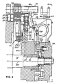
Fig. 2 is a fragmentary cross-section of the mandrel carrier assembly taken through line 2-2 ofFig. 1 looking in the direction of arrows 2-2. -
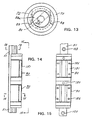
Fig. 3 is a fragmentary front elevation of the mandrel carrier assembly looking in the direction of arrows 3-3 ofFig. 2 . -
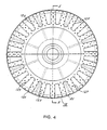
Fig. 4 is a rear elevation of the mandrel carrier and elements welded thereto. -
Fig. 5 is a gross-section taken through line 5-5 ofFig. 4 looking in the direction of arrows 5-5. -
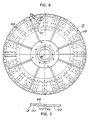
Fig. 6 is a front elevation of the assembly inFig. 5 . -
Fig. 7 is a fragmentary edge view of the mandrel carrier. -
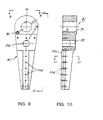
Fig. 8 is a front elevation of the support arm of a mandrel subassembly. -
Fig. 9 is an elevation looking in the direction of arrows 9-9 inFig. 8 at the radially outer end of the support arm. -
Fig. 10 is a side elevation, partially sectioned, of the support arm looking in the direction of arrows 10-10 inFig. 8 . -
Fig. 11 is a cross-section taken through line 11-11 inFig. 10 looking in the direction of arrows 11-11. -
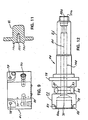
Fig. 12 is a side elevation of an axle which includes a spindle section on which a mandrel is rotatably mounted. -
Fig. 13 is an elevation looking at the rear end of the axle inFig. 12 . -
Fig. 14 is a side elevation of two elongated roller-type linear slides in operative engagement with a mono rail of a mandrel subassembly. -
Fig. 15 is a front elevation of the elements inFig. 14 looking in the direction of arrows 15-15 inFig. 14 . -
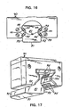
Fig. 16 is a schematic end view of a mono rail engaged with the rollers of a linear slide. -
Fig. 17 is a fragmentary perspective illustrating an end portion of the mono rail partially engaged with a linear slide. - Now referring to the Figures and more particularly to
Fig. 1 which illustrates continuous motion cylindrical container decorating apparatus of the general type described in the aforesaidU.S. Patents Nos. 3,766,851 and5,111,742 . The apparatus ofFig. 1 includes infeedconveyor chute 15 which receives undecorated containers in the form ofbeverage cans 16, each open at one end thereof, from a can supply (not shown) andplaces cans 16 in arcuate cradles or pockets 17 formed by aligned depressions in the outer edges of spaced segmented rings 31, 32 (Fig. 2 ). The latter are Fixedly secured to supportring 33 that is positioned in front of and secured to disc-like mandrel carrier 18 on eight angularly spacedstandoffs 48.Screws 43 secure the segments ofpocket rings 31, 32 to supportring 33. -
Carrier 18 is mounted on continuously rotatinghorizontal drive shaft 19 whose first end (toward the left inFig. 2 ) is rotatably supported on a fixed portion of the frame of the decorating apparatus illustrated inFig. 1 . Shaft 19 is drivingly connected tocarrier 18 by key 45 that engagestapered sleeve 46 which is wedged betweendrive shaft 19 andhub 47. The latter is welded tocarrier 18 at the center thereof. - Horizontally extending mandrels 20 (
Fig. 2 ) are also mounted tocarrier 18, with eachmandrel 20 being in spaced horizontal alignment with an individual pocket 17 while passing through a short loading region extending downstream from infeedconveyor 15. In this short region,undecorated cans 16 are moved horizontally rearward by a deflector (not shown), being transferred from each cradle 17 to anindividual mandrel 20. Suction applied through an axial passage 148 (Fig. 12 ) extending to the outboard or front end 21a ofspindle shaft 21 on whichmandrel 20 rotates freely, drawscontainer 16 rearward (to the left with respect toFig. 2 ) to final seating position onmandrel 20. - While mounted on
mandrels 20,cans 16 are decorated by being brought into engagement with continuously rotating image transfer mat orprinting blanket 91 of the multicolored printing press decorating section indicated generally byreference numeral 222. Thereafter, and while mounted tomandrels 20, each decorated can 16 is coated with a protective film of varnish applied thereto by engagement with the periphery ofapplicator roll 23 in the overvarnish unit indicated generally bynumeral 24.Cans 16 with decorations and protective coatings thereon are then transferred fromspindles 20 to suction cups (not shown) mounted near the periphery oftransfer wheel 27 while the latter rotates aboutshaft 28 as a center.Cans 16 carried bytransfer wheel 27 are deposited on generallyhorizontal pins 29 which project from chaintype output conveyor 30 that carriescans 16 through a curing oven (not shown). - By the
time mandrel 20 moves beyond the downstream end ofchute 15 and is in the proximity of sensor 133, eachmandrel 20 should be properly loaded with acan 16. If sensor 133 detects that amandrel 20 is unloaded or is not properly loaded, then before thisparticular mandrel 20 enters the decorating zone whereinprinting blanket 91 normally engages can 16 onmandrel 20, this unloaded ormisloaded mandrel 20 is moved to a tripped or "no-print" position relative toprinting blanket 91. As a trippedmandrel 20 moves through the decorating zone it will be spaced from the periphery ofblanket 91. This no-print position is achieved by controllingdouble acting cylinder 34 to tripsubframe 35 havingmandrel carrier shaft 19 mounted thereon, by movingsubframe 35 to the left with respect toFig. 1 whilemain base 36, to whichprinting unit 22 is mounted, remains stationary. Further, actuation of sensor 133 causes overvarnishunit 24 to move downward with respect tomandrel carrying shaft 19 so that the trippedspindles 20 do not engageovervarnish application roll 23. -
Mandrel 20 is part ofmandrel subassembly 40 that also includes support arm or base 41 (Fig. 8 ), shaft 44 (Fig. 12 ), rigidstraight rail 51 and twocam follower rollers Spindle 21 is the front portion ofshaft 44 and extends forward fromarm 41 near its radially outer end, being perpendicular thereto and parallel tocarrier shaft 19.Follower rollers arm 41, being rotatably mounted onstub shaft 61 that projects fromaperture 59 which extends througharm 41 radially inward ofshaft 44. Closedloop cam track 55 surrounds mandreldisc drive shaft 19 and receivesfollowers cam 55 andfollowers rotational axes shaft 19 andspindles 21, respectively. - With particular reference to
Figs. 8-11 it is seen thatsupport arm 41 is an elongated member that is tapered lengthwise, being widest at its radially outer end wherestub shaft 44 andcam follower rollers Aperture 71 inarm 41 is disposed radially outward ofaperture 59 and is provided to receive mounting section 22 (Fig. 12 ) at the rear end ofshaft 44. The outercylindrical surface 72 ofshaft 44 to the rear ofaxle shoulder 73 is closely fitted to the inner cylindrical surface ofaperture 71. As will hereinafter be explained,shaft 44 is pivotable relative toarm 41 about theaxis 74 about which surface 72 is formed. - Pressurized air and vacuum are selectively supplied to
aperture 71 through L-shapedpassage 81 whose outer end is connected throughrigid stub pipes Fig. 2 ) at one end offlexible hose 83. The inner end ofpassage 81 communicates with circular undercut 86 in mountingsurface 72 ofshaft 44 andtransverse passages passage 148 that extends axially throughshaft 44 so that pressurized air and vacuum can be present at the forward end ofspindle 21. The end ofhose 83 remote from fitting 82 is provided with fitting 84 that is connected throughrigid stub pipe 85a to supply passage 85bwhich extends through movableface valve member 75 that is connected tohub 47 for continuous rotation therewith. - Each airway between a passage 85b and the outer end of a
passage 81 consists offlexible hose 83 andrigid stub pipes Fig. 2 , the vast majority of the length ofhose 83 is bent to form a single loop with very short portions ofhose 83 being required to connect such single loop topipes hose 83 is positioned so that side portions thereof do not rub against other side portions thereof or rub against other elements of the apparatus. Hose life is shortened very quickly in theevent hose 83 rubs against another element or portions of the hose rub against each other. - At its
rear end 88a,longitudinal passage 148 is enlarged and is provided with an internal thread that is engaged byretainer 188 which drawsshoulder 73 against the front end ofarm 41 to secureaxle 44 toarm 41. At its front end 88b,longitudinal passage 148 is threaded internally to receive a screw (not shown) that retainsmandrel 20 mounted onspindle shaft 21. - Threaded
apertures aperture 71 and are positioned so that adjusting screws 76, 77 which extend throughrespective apertures arm 41 to adjust the angular position ofaxle 44. That is, when screws 76, 77 move inward throughapertures respective ledges surface 72. Topivot axle 44, say clockwise when looking at its front or spindle end, screw 76 must be backed away fromledge 88 and then screw 77 is turned inward againstledge 89 untilaxle 44 reaches a desired angular position by turning clockwise about mountingaxis 74. The latter axis is parallel to but slightly eccentric with respect tospindle axis 85 so that asaxle 44 pivots the spacing betweenspindle axis 85 andaxis 80 ofmandrel carrier 18 changes. After the desired spacing betweenaxes ledge 88 to lockaxle 44 against pivoting about mountingaxis 74. Topivot axle 44 counterclockwise, screw 77 is backed away fromledge 89, then screw 76 is turned inward againstledge 88 to pivotaxle 44 counterclockwise untilspindle 21 reaches its required position, and then screw 77 is moved forward againstledge 79 to lockaxle 44 against pivoting. - Now referring more particularly to
Figs. 5-8 ,carrier 18 is a steel disc that carries twenty-four (24)mandrel subassemblies 40 that are in a generally circular array aboutcarrier axis 80 as a center. The major portion of each subassembly is arranged to reciprocate radially with respect toaxis 80, being guided by the cooperation ofmono rail 51 and a pair of aligned cylindrical roller-type bearing units orlinear slides rail 51 extends. A suitable mono rail structure for the decorating apparatus of the instant invention is marketed by Schneeberger Inc., having a place of business located in Bedford, MA 01730 USA. - Rail 51 (
Figs. 16 and 17 ) of such mono rail structure is an elongated member which includesrear wall 91 and shortparallel sidewall sections rear wall 91. Located at each side ofrail 51 and extending forward from eachwall section 92 are a pair of flat longitudinal guide surfaces 93, 93.Bearing elements 95 of twoslides 90 ride on eachsurface 93. The pair of guide surfaces 93, 93 on the right ofFig. 16 are at right angles to each other and the rear one of this pair is at 45° with respect toright wall section 92. Similarly, the pair of guide surfaces 93, 93 on the left inFig. 16 are mirror images of theother pair lock rail 51 from pivoting clockwise or counterclockwise about the longitudinal axis ofrail 51. Eachlinear slide 90 includes fourarrays 94 of bearingelements 95, one for eachrail surface 93, with each bearing array being disposed to move along an individual raceway (not shown) which is formed inhousing 180 ofslide unit 90 so that, as seen inFig. 17 , a portion of each array is exposed to engage arail surface 93. - Unless precautions are taken to restrain bearing
elements 95, one or more of them can separate easily frombase 180 and compromise the integrity of assembly betweenrail 51 and bearingunits Fig. 3 ) is removably secured to the radially inner end ofarm 41 to prevent separation betweenrail 51 ofsubassembly 40 and slides 90, 90. That is, there will be interference betweenslides retainer 201 so long asscrew 202 securesretainer 201 in its operative position at the radially inner end ofrail 51. The enlarged radially outer end ofarm 41 blocks removal ofslides rail 51. - Positional integrity of
rail 51 relative toarm 41 is achieved by fasteningscrews 96 that extend throughindividual clearance apertures 103 inrail 51 and are received by individual threadedapertures 104 inarm 41.Arm 41 also includes shallow longitudinal channel 102 (Fig. 11 ) defined by a pair of shortparallel arms arm 41. Theshort sidewalls rail 51enter channel 102 and are fitted tightly betweenarms block guide rail 51 from movement about axes that extend at right angles torear wall 91. - Positional integrity of
subassembly 40 is controlled to a great extent by rigidly positioning slides 90, 90 oncarrier 18. More particularly, carrier 18 (Figs. 4-7 ) is a steel disk having flatfront surface 128 andrear surface 129 that is machined to form an individual shallowradial groove 125 for the pair ofslides subassemblies 40. For eachgroove 125,carrier 18 is provided with eightclearance apertures 126 that are aligned with the respective threadedapertures 136 at the front ofslides apertures 126. For eachgroove 125,carrier 18 is also provided with a pair ofclearance apertures 127 that are aligned withrespective openings 137 at the front ofslides apertures 127 toopenings 137 lubricates the elongated bearing elements 140 ofslides apertures 136 are infront wall 151 ofslide 90, whichwall 151 is drawn against thebottom wall 152 ofgroove 125 and short side walls 153, 153 ofgroove 125 are fitted tightly againstslide 90 with screws 203. - Application of pressurized air and vacuum to
hoses 83 is under the control of a face-valve arrangement that includesstationary valve elements 199 mounted at the front of stationary frame member 99 androtating wear plate 198 having apertures aligned with one end ofchannels 85 inhub attachment 75. - Each of the four longitudinal bearing faces 93 of
rail 51 is in sliding engagement with an individual partial array of bearingelements 95 of twoslides rail 51 is constrained to reciprocate radially. Each of the bearingelements 95 is cylindrical with a length transverse to bearingface 93, that is greater than the diameter of theelements 95. The cylindrical surfaces ofelements 95 are parallel to each other and extend crosswise with respect to the length of bearing faces 93 which they engage. - For each
slide 90, each of the four bearing element arrays occupies anindividual raceway 191 in the housing 160 ofslide 90. The bearingelements 95 of the partial array are disposed with their cylindrical axes in a plane that is parallel to the bearingface 93 with which the partial array is engaged.
Claims (14)
- Continuous motion apparatus for decorating cylindrical containers (16), said apparatus comprising a decorating section and a transport section that carries containers (16) through a decorating zone (222) where decorations are applied to the containers (16), said transport section including:a carrier (18) continuously rotating on a carrier axis (80), said carrier (18) having a front facing side, a plurality of mandrel subassemblies (40) mounted on said carrier (18) with equal angular spacings between adjacent ones of said subassemblies (40), each of said subassemblies (40) being mounted to reciprocate along an individual path that is disposed radially relative to said carrier axis (80) as a center,characterized in that:each of said subassemblies (40) includes an elongated support arm (41) extending lengthwise of an individual one of said paths, an axle (44) extending forward from said arm (41) and being generally parallel to said carrier axis (80), and a rail (51) secured to said arm (41) and extending lengthwise thereof;said axle (44) includes a spindle section for supporting a rotatable mandrel (20) that carries containers (16) through said decorating zone, said axle (44) also including a mounting section (22) rearward of said spindle section, said mounting section (22) being connected to said arm (41) at a radially outer end of said arm (41);for each of said subassemblies (40), at least one slide unit (90) is secured to said front facing side of said carrier (18) and is operatively engaged with said rail (51) to slidably support said subassembly (40) as it reciprocates radially;each of said rails (51) has at least one bearing surface (93) each of which is engaged by a different group of bearing elements (95) of said at least one slide unit (90).
- Apparatus for decorating cylindrical containers (16) as defined by claim 1 in which said bearing elements (95) extend crosswise of said path.
- Apparatus for decorating cylindrical containers (16) as defined by claim 2 in which each of said bearing elements (95) is cylindrical with a length to diameter ratio which is substantially greater than one.
- Apparatus for decorating cylindrical containers (16) as defined in claim 1, in which said rear mounting section (22) has a cylindrical outer surface (72) and is disposed within a recess (71) of said arm (41), said recess (71) having a cylindrical inner surface that is closely fitted to said outer surface (72), with said inner and outer surfaces (72) having a common mounting axis (74) about which said axle (44) is pivotable to operatively position said spindle (21) relative to said carrier axis (80) in that said spindle (21) is provided with a longitudinal axis (85) that is parallel to said mounting axis (74) and is eccentric with respect thereto and elements connected with said spindle (21) for adjusting the rotation orientation of said axle (44) to move said spindle axis (85) to adjust the printing pressure on a container (16) on the respective said mandrel (20).
- Apparatus for decorating cylindrical containers (16) as defined by claim 4 also including first and second adjusting screws (76, 77) for each of said subassemblies (40), said screws (76, 77) threadably mounted to said arm (41) with each of said screws (76, 77) having an outer end that is engageable from outside of said arm (41) and an inner end that extends into said recess (71) to engage an individual ledge (88, 89) cut in said outer surface (72) of said mounting section (22);
said inner ends of the respective first and second screws (76, 77) engaging a respective first and second of said ledges (88, 89) which are positioned so that with said second screw (77) withdrawn from said second ledge (89), turning of said first screw (76) inward while engaged with said first ledge (88) pivots said axle (44) in a first direction about said mounting axis (74), and with said first screw (76) withdrawn from said first ledge (88), turning of said second screw (77) inward while engaged with said second ledge (89) pivots said axle (44) in a second direction about said mounting axis (74), with said second direction being opposite to said first direction. - Apparatus for decorating cylindrical containers (16) as defined by claim 5 in which:after inward turning of said first screw (76) to pivot said axle (44) to a first angular position, inward turning of said second screw (77) into engagement with said second ledge (89) locks said axle (44) in said first angular position; andafter inward turning of said second screw (77) to pivot said axle (44) to a second angular position, inward turning of said first screw (76) into engagement with said first ledge (88) locks said axle (44) in said second angular position.
- Apparatus for decorating cylindrical containers (16) as defined by claim 1 in which each of said arms (41) is provided with a shallow longitudinally extending groove (102) that is defined by a pair of spaced parallel groove walls that are tightly fitted against opposite side portions (92) of said rail (51) that is entered into said groove.
- Apparatus for decorating cylindrical containers (16) as defined by claim 4 in which each of said arms (41) is provided with a shallow longitudinally extending groove (102) that is defined by a pair of spaced parallel arms (101) that are tightly fitted against opposite sidewalls (92) of said rail (51) that is entered into said groove (102).
- Apparatus for decorating cylinder containers (16) defined by Claim 1, further comprising:an individual airway for each of said mandrel subassemblies (40) through which vacuum and pressurized air is supplied selectively to said mandrel (20), the vacuum acting to hold a can (16) loaded on said mandrel (20) and the pressurized air acting to unload a can (16) from said mandrel (20);said airway extending between said support arm (41) and said carrier (18), and including a flexible section (83) having a length whose vast majority is curved into a single loop.
- Apparatus for decorating cylindrical containers (16) as defined by claim 9 in which said airway, except for said flexible section (83), is rigid.
- Apparatus for decorating cylindrical containers (16) as defined by claim 9 in which one end of said loop coincides essentially with one end of said flexible section (83) and at the other end of said flexible section (83) extends beyond said loop.
- Apparatus for decorating cylindrical containers (16) as defined by claim 11 in which said one end of said flexible section (83) is connected to said carrier (18) and is radially inboard of said other end of said flexible section (83).
- Apparatus for decorating cylindrical containers (16) as defined by Claim 1, further comprising
each of said subassemblies (40) including a removable retainer (201) to maintain engagement between said rail (51) and said at least one slide unit (90) when said at least one slide unit (90) is dismounted from said carrier (18). - Apparatus for decorating cylindrical containers (16) as defined by claim 13 in which said retainer (201) is mountable on said support arm (41) at its radially inner end.
Applications Claiming Priority (3)
| Application Number | Priority Date | Filing Date | Title |
|---|---|---|---|
| US248247 | 1981-03-27 | ||
| US09/248,247 US6167805B1 (en) | 1999-02-10 | 1999-02-10 | Mandrel carrier for high speed can decorators |
| PCT/US2000/002590 WO2000047415A1 (en) | 1999-02-10 | 2000-02-01 | Mandrel carrier for high speed can decorators |
Publications (3)
| Publication Number | Publication Date |
|---|---|
| EP1165318A1 EP1165318A1 (en) | 2002-01-02 |
| EP1165318A4 EP1165318A4 (en) | 2008-02-27 |
| EP1165318B1 true EP1165318B1 (en) | 2009-12-09 |
Family
ID=22938290
Family Applications (1)
| Application Number | Title | Priority Date | Filing Date |
|---|---|---|---|
| EP00913327A Expired - Lifetime EP1165318B1 (en) | 1999-02-10 | 2000-02-01 | Mandrel carrier for high speed can decorators |
Country Status (16)
| Country | Link |
|---|---|
| US (1) | US6167805B1 (en) |
| EP (1) | EP1165318B1 (en) |
| JP (1) | JP4663882B2 (en) |
| KR (1) | KR20020042758A (en) |
| CN (1) | CN1139486C (en) |
| AT (1) | ATE451237T1 (en) |
| AU (1) | AU767759C (en) |
| BR (1) | BR0008099B1 (en) |
| CA (1) | CA2362340C (en) |
| CZ (1) | CZ297591B6 (en) |
| DE (1) | DE60043500D1 (en) |
| HK (1) | HK1045967A1 (en) |
| MX (1) | MXPA01008111A (en) |
| NZ (1) | NZ513260A (en) |
| RU (1) | RU2232078C2 (en) |
| WO (1) | WO2000047415A1 (en) |
Cited By (1)
| Publication number | Priority date | Publication date | Assignee | Title |
|---|---|---|---|---|
| DE102016201140A1 (en) * | 2016-01-27 | 2017-07-27 | Kba-Metalprint Gmbh | Method for operating a device having a segment wheel for printing hollow bodies |
Families Citing this family (49)
| Publication number | Priority date | Publication date | Assignee | Title |
|---|---|---|---|---|
| US20070129151A1 (en) * | 2001-08-20 | 2007-06-07 | Crowder Robert W Jr | Game Conversion Method |
| US6840166B2 (en) * | 2002-06-12 | 2005-01-11 | Machine Engineering, Inc. | Mandrel trip apparatus |
| US6651552B1 (en) * | 2002-07-22 | 2003-11-25 | Sequa Can Machinery, Inc. | Automated can decorating apparatus having mechanical mandrel trip |
| US6769357B1 (en) | 2003-06-05 | 2004-08-03 | Sequa Can Machinery, Inc. | Digital can decorating apparatus |
| EP2026980B1 (en) * | 2006-05-10 | 2013-04-10 | V.I.V. International S.p.A. | Apparatus for decorating objects |
| WO2009018892A1 (en) | 2007-08-03 | 2009-02-12 | Khs Ag | Device for printing containers |
| EP2207684B1 (en) | 2007-10-19 | 2011-11-23 | KHS GmbH | Apparatus for printing bottles or similar containers on the outer container surface |
| EP2159054A1 (en) * | 2008-08-29 | 2010-03-03 | Polytype S.A. | Printing mandrel for fixing a basically hollow cylindrical body, in particular tubular bodies |
| US8596625B2 (en) | 2010-06-09 | 2013-12-03 | Stolle Machinery Company, Llc | Self-aligning pivotable mandrel assembly |
| US8596624B2 (en) * | 2010-06-09 | 2013-12-03 | Stolle Machinery Company, Llc | Self-aligning pivotable mandrel assembly |
| US9475276B2 (en) | 2011-04-27 | 2016-10-25 | Stolle Machinery Company, Llc | Can decorator machine, ink station assembly therefor, and can decorating method employing same |
| CN102848722B (en) * | 2011-06-29 | 2015-02-25 | 李华容 | Continuous jet printing method and device |
| US8707866B2 (en) | 2012-03-21 | 2014-04-29 | James M. Jeter | Rail guide mounting assembly for mandrel trip apparatus |
| JP2015520048A (en) * | 2012-04-26 | 2015-07-16 | ストール マシーナリ カンパニー, エルエルシーStolle Machinery Company, LLC | Self-aligning pivotable mandrel assembly |
| NL1040447C2 (en) * | 2013-10-15 | 2015-04-16 | Upg Engineering | MANDREL WHEEL FOR CONTINUOUS MOTION PRESSURE OR PAINTING MACHINE. |
| DE102014213813B4 (en) | 2014-07-16 | 2018-01-04 | Kba-Metalprint Gmbh | Device for printing in each case a lateral surface of hollow bodies |
| DE102014213804A1 (en) | 2014-07-16 | 2016-01-21 | Kba-Metalprint Gmbh | Inking unit of a printing unit |
| EP3169519B1 (en) | 2014-07-16 | 2018-04-25 | KBA-MetalPrint GmbH | Printing unit with plate cylinder and plate changing device |
| WO2016008701A1 (en) | 2014-07-16 | 2016-01-21 | Kba-Metalprint Gmbh | Inking unit of a printing unit |
| DE102014213805B3 (en) * | 2014-07-16 | 2014-12-31 | Kba-Metalprint Gmbh | Inking unit of a printing unit |
| PL3169521T3 (en) | 2014-07-16 | 2018-07-31 | Kba-Metalprint Gmbh | Device for printing hollow articles |
| DE102014213811A1 (en) | 2014-07-16 | 2016-01-21 | Kba-Metalprint Gmbh | Printing unit with a printing forme cylinder |
| DE102014213807B4 (en) | 2014-07-16 | 2017-12-21 | Kba-Metalprint Gmbh | Apparatus for printing on each of a lateral surface having hollow bodies |
| DE102014213812B3 (en) * | 2014-07-16 | 2014-12-18 | Kba-Metalprint Gmbh | Device for arranging a printing form cylinder and an inking unit of a printing unit |
| DE102016201139B4 (en) | 2016-01-27 | 2019-01-10 | Kba-Metalprint Gmbh | Device for printing hollow bodies |
| DE102016201137B4 (en) | 2016-01-27 | 2018-12-27 | Kba-Metalprint Gmbh | Device for printing hollow bodies |
| US10780714B2 (en) | 2016-12-16 | 2020-09-22 | Stolle Machinery Company, Llc | Mandrel for printing necked cans |
| US10155375B2 (en) | 2016-12-16 | 2018-12-18 | Stolle Machinery Company, Llc | Mandrel for printing necked cans |
| DE102017201921B4 (en) | 2017-02-08 | 2022-02-17 | Koenig & Bauer Ag | Device for printing hollow bodies |
| DE102017202384A1 (en) | 2017-02-15 | 2018-08-16 | Kba-Metalprint Gmbh | Method for printing hollow bodies |
| DE102017202381A1 (en) | 2017-02-15 | 2018-08-16 | Kba-Metalprint Gmbh | Method for printing hollow bodies |
| DE102017202382A1 (en) | 2017-02-15 | 2018-08-16 | Kba-Metalprint Gmbh | Method for operating a device for printing hollow bodies |
| DE102017206392A1 (en) | 2017-04-13 | 2018-10-18 | Koenig & Bauer Ag | Segmented wheel of a device for printing hollow bodies |
| US10259249B2 (en) * | 2017-07-14 | 2019-04-16 | Stolle Machinery Company, Llc | Post-treatment assembly and method for treating work pieces |
| DE102018201033B3 (en) | 2018-01-24 | 2018-10-31 | Koenig & Bauer Ag | Device for printing hollow bodies |
| CN114734724A (en) * | 2018-03-14 | 2022-07-12 | 斯多里机械有限责任公司 | Decorator assembly |
| WO2020072061A1 (en) | 2018-10-04 | 2020-04-09 | Vinventions Usa, Llc | Mandrel and mounting device for receiving a hollow cylindrical object |
| WO2019178591A1 (en) | 2018-03-16 | 2019-09-19 | Vinventions Usa, Llc | Tiltable mounting device, printing system and method for printing on cylindrical objects |
| DE102018121537A1 (en) * | 2018-09-04 | 2020-03-05 | Koenig & Bauer Ag | Production plant for printing on hollow bodies |
| DE102018121542B4 (en) | 2018-09-04 | 2022-03-17 | Koenig & Bauer Ag | Device for printing hollow bodies |
| DE102018121540A1 (en) * | 2018-09-04 | 2020-03-05 | Koenig & Bauer Ag | Device for printing on hollow bodies |
| WO2020097451A1 (en) | 2018-11-09 | 2020-05-14 | Ball Corporation | A metering roller for an ink station assembly of a decorator and a method of decorating a container with the decoration |
| DE102019123633A1 (en) * | 2019-09-04 | 2021-03-04 | Koenig & Bauer Ag | Inking unit of a printing press |
| DE102019123632A1 (en) * | 2019-09-04 | 2021-03-04 | Koenig & Bauer Ag | Container for providing printing ink in an inking unit of a printing machine |
| DE102019123634A1 (en) * | 2019-09-04 | 2021-03-04 | Koenig & Bauer Ag | Ink stirrer for circulating printing ink in an ink pan arranged in an inking unit of a printing machine and inking unit of a printing machine with this ink stirrer |
| DE102019123631A1 (en) * | 2019-09-04 | 2021-03-04 | Koenig & Bauer Ag | Inking unit of a printing press |
| DE102019125130B4 (en) | 2019-09-18 | 2022-07-14 | Koenig & Bauer Ag | Device for printing the respective outer surface of hollow bodies |
| DE102019129926B4 (en) | 2019-11-06 | 2022-09-08 | Koenig & Bauer Ag | Process and device for printing the respective lateral surface of hollow bodies |
| JP6791422B2 (en) * | 2020-04-23 | 2020-11-25 | 東洋製罐株式会社 | Printing press and printing press status monitoring method |
Family Cites Families (8)
| Publication number | Priority date | Publication date | Assignee | Title |
|---|---|---|---|---|
| US3766851A (en) | 1971-11-15 | 1973-10-23 | Sun Chemical Corp | Continuous can printer and handling apparatus |
| US4018151A (en) * | 1975-12-08 | 1977-04-19 | Crown Cork & Seal Company, Inc. | Apparatus for varying a cyclic path |
| US4140053A (en) | 1977-06-16 | 1979-02-20 | Sun Chemical Corporation | Mandrel mounting and trip mechanism for continuous motion decorator |
| US4498387A (en) * | 1983-10-21 | 1985-02-12 | Adolph Coors Company | Cam assembly for skip-print mandrel wheel assembly |
| NL192329C (en) | 1986-07-04 | 1997-06-04 | Thomassen & Drijver | Device for printing cups or cans. |
| US5111742A (en) | 1990-08-13 | 1992-05-12 | Sequa Corporation | Mandrel trip subassembly for continuous motion can decorators |
| US5572927A (en) | 1995-08-31 | 1996-11-12 | Sequa Corporation | Vertical track for mandrel assembly of continuous motion can decorators |
| US5799574A (en) | 1997-06-16 | 1998-09-01 | Sequa Corporation | Spindle disc for high speed can decorators |
-
1999
- 1999-02-10 US US09/248,247 patent/US6167805B1/en not_active Expired - Lifetime
-
2000
- 2000-02-01 DE DE60043500T patent/DE60043500D1/en not_active Expired - Lifetime
- 2000-02-01 BR BRPI0008099-3A patent/BR0008099B1/en not_active IP Right Cessation
- 2000-02-01 AU AU34794/00A patent/AU767759C/en not_active Ceased
- 2000-02-01 RU RU2001124824/12A patent/RU2232078C2/en active
- 2000-02-01 KR KR1020017010150A patent/KR20020042758A/en not_active Application Discontinuation
- 2000-02-01 CZ CZ20012852A patent/CZ297591B6/en not_active IP Right Cessation
- 2000-02-01 CN CNB008036403A patent/CN1139486C/en not_active Expired - Lifetime
- 2000-02-01 CA CA002362340A patent/CA2362340C/en not_active Expired - Lifetime
- 2000-02-01 WO PCT/US2000/002590 patent/WO2000047415A1/en active IP Right Grant
- 2000-02-01 AT AT00913327T patent/ATE451237T1/en not_active IP Right Cessation
- 2000-02-01 NZ NZ513260A patent/NZ513260A/en unknown
- 2000-02-01 EP EP00913327A patent/EP1165318B1/en not_active Expired - Lifetime
- 2000-02-01 JP JP2000598354A patent/JP4663882B2/en not_active Expired - Lifetime
- 2000-02-01 MX MXPA01008111A patent/MXPA01008111A/en active IP Right Grant
-
2002
- 2002-10-21 HK HK02107612A patent/HK1045967A1/en not_active IP Right Cessation
Cited By (2)
| Publication number | Priority date | Publication date | Assignee | Title |
|---|---|---|---|---|
| DE102016201140A1 (en) * | 2016-01-27 | 2017-07-27 | Kba-Metalprint Gmbh | Method for operating a device having a segment wheel for printing hollow bodies |
| DE102016201140B4 (en) * | 2016-01-27 | 2018-05-03 | Kba-Metalprint Gmbh | Method for operating a device having a segment wheel for printing hollow bodies |
Also Published As
| Publication number | Publication date |
|---|---|
| KR20020042758A (en) | 2002-06-07 |
| CA2362340C (en) | 2009-12-08 |
| JP2003524536A (en) | 2003-08-19 |
| EP1165318A1 (en) | 2002-01-02 |
| CZ297591B6 (en) | 2007-02-07 |
| CN1139486C (en) | 2004-02-25 |
| AU767759B2 (en) | 2003-11-20 |
| MXPA01008111A (en) | 2002-07-30 |
| US6167805B1 (en) | 2001-01-02 |
| AU3479400A (en) | 2000-08-29 |
| DE60043500D1 (en) | 2010-01-21 |
| BR0008099B1 (en) | 2010-07-27 |
| CA2362340A1 (en) | 2000-08-17 |
| CN1348412A (en) | 2002-05-08 |
| ATE451237T1 (en) | 2009-12-15 |
| RU2232078C2 (en) | 2004-07-10 |
| WO2000047415A9 (en) | 2001-10-18 |
| JP4663882B2 (en) | 2011-04-06 |
| NZ513260A (en) | 2004-02-27 |
| AU767759C (en) | 2004-07-29 |
| WO2000047415A1 (en) | 2000-08-17 |
| HK1045967A1 (en) | 2002-12-20 |
| CZ20012852A3 (en) | 2002-02-13 |
| BR0008099A (en) | 2001-11-06 |
| EP1165318A4 (en) | 2008-02-27 |
Similar Documents
| Publication | Publication Date | Title |
|---|---|---|
| EP1165318B1 (en) | Mandrel carrier for high speed can decorators | |
| AU727160B2 (en) | Spindle disc for high speed can decorators | |
| CA1298968C (en) | Container transfer system | |
| EP0847332B1 (en) | Vertical track for mandrel assembly of continuous motion can decorators | |
| EP1551632B1 (en) | Mechanical mandrel trip | |
| EP0471512B1 (en) | Mandrel trip subassembly for continuous motion can decorators | |
| AU700402B2 (en) | Face valve apparatus for continuous motion can decorator | |
| MXPA98001618A (en) | Vertical track for mandrel unit of container movement cans |
Legal Events
| Date | Code | Title | Description |
|---|---|---|---|
| PUAI | Public reference made under article 153(3) epc to a published international application that has entered the european phase |
Free format text: ORIGINAL CODE: 0009012 |
|
| 17P | Request for examination filed |
Effective date: 20010808 |
|
| AK | Designated contracting states |
Kind code of ref document: A1 Designated state(s): AT BE CH CY DE DK ES FI FR GB GR IE IT LI LU MC NL PT SE |
|
| A4 | Supplementary search report drawn up and despatched |
Effective date: 20080128 |
|
| 17Q | First examination report despatched |
Effective date: 20080428 |
|
| GRAP | Despatch of communication of intention to grant a patent |
Free format text: ORIGINAL CODE: EPIDOSNIGR1 |
|
| GRAS | Grant fee paid |
Free format text: ORIGINAL CODE: EPIDOSNIGR3 |
|
| GRAA | (expected) grant |
Free format text: ORIGINAL CODE: 0009210 |
|
| RAP1 | Party data changed (applicant data changed or rights of an application transferred) |
Owner name: STOLLE MACHINERY COMPANY, LLC |
|
| AK | Designated contracting states |
Kind code of ref document: B1 Designated state(s): AT BE CH CY DE DK ES FI FR GB GR IE IT LI LU MC NL PT SE |
|
| REG | Reference to a national code |
Ref country code: GB Ref legal event code: FG4D |
|
| REG | Reference to a national code |
Ref country code: CH Ref legal event code: EP |
|
| REG | Reference to a national code |
Ref country code: IE Ref legal event code: FG4D |
|
| REF | Corresponds to: |
Ref document number: 60043500 Country of ref document: DE Date of ref document: 20100121 Kind code of ref document: P |
|
| PG25 | Lapsed in a contracting state [announced via postgrant information from national office to epo] |
Ref country code: SE Free format text: LAPSE BECAUSE OF FAILURE TO SUBMIT A TRANSLATION OF THE DESCRIPTION OR TO PAY THE FEE WITHIN THE PRESCRIBED TIME-LIMIT Effective date: 20091209 Ref country code: FI Free format text: LAPSE BECAUSE OF FAILURE TO SUBMIT A TRANSLATION OF THE DESCRIPTION OR TO PAY THE FEE WITHIN THE PRESCRIBED TIME-LIMIT Effective date: 20091209 |
|
| PG25 | Lapsed in a contracting state [announced via postgrant information from national office to epo] |
Ref country code: AT Free format text: LAPSE BECAUSE OF FAILURE TO SUBMIT A TRANSLATION OF THE DESCRIPTION OR TO PAY THE FEE WITHIN THE PRESCRIBED TIME-LIMIT Effective date: 20091209 |
|
| PG25 | Lapsed in a contracting state [announced via postgrant information from national office to epo] |
Ref country code: PT Free format text: LAPSE BECAUSE OF FAILURE TO SUBMIT A TRANSLATION OF THE DESCRIPTION OR TO PAY THE FEE WITHIN THE PRESCRIBED TIME-LIMIT Effective date: 20100409 Ref country code: ES Free format text: LAPSE BECAUSE OF FAILURE TO SUBMIT A TRANSLATION OF THE DESCRIPTION OR TO PAY THE FEE WITHIN THE PRESCRIBED TIME-LIMIT Effective date: 20100320 |
|
| PG25 | Lapsed in a contracting state [announced via postgrant information from national office to epo] |
Ref country code: BE Free format text: LAPSE BECAUSE OF FAILURE TO SUBMIT A TRANSLATION OF THE DESCRIPTION OR TO PAY THE FEE WITHIN THE PRESCRIBED TIME-LIMIT Effective date: 20091209 |
|
| REG | Reference to a national code |
Ref country code: CH Ref legal event code: PL |
|
| PLBE | No opposition filed within time limit |
Free format text: ORIGINAL CODE: 0009261 |
|
| STAA | Information on the status of an ep patent application or granted ep patent |
Free format text: STATUS: NO OPPOSITION FILED WITHIN TIME LIMIT |
|
| PG25 | Lapsed in a contracting state [announced via postgrant information from national office to epo] |
Ref country code: CH Free format text: LAPSE BECAUSE OF NON-PAYMENT OF DUE FEES Effective date: 20100228 Ref country code: MC Free format text: LAPSE BECAUSE OF NON-PAYMENT OF DUE FEES Effective date: 20100301 Ref country code: LI Free format text: LAPSE BECAUSE OF NON-PAYMENT OF DUE FEES Effective date: 20100228 Ref country code: GR Free format text: LAPSE BECAUSE OF FAILURE TO SUBMIT A TRANSLATION OF THE DESCRIPTION OR TO PAY THE FEE WITHIN THE PRESCRIBED TIME-LIMIT Effective date: 20100310 Ref country code: CY Free format text: LAPSE BECAUSE OF FAILURE TO SUBMIT A TRANSLATION OF THE DESCRIPTION OR TO PAY THE FEE WITHIN THE PRESCRIBED TIME-LIMIT Effective date: 20091209 |
|
| 26N | No opposition filed |
Effective date: 20100910 |
|
| REG | Reference to a national code |
Ref country code: FR Ref legal event code: ST Effective date: 20101029 |
|
| PG25 | Lapsed in a contracting state [announced via postgrant information from national office to epo] |
Ref country code: DK Free format text: LAPSE BECAUSE OF FAILURE TO SUBMIT A TRANSLATION OF THE DESCRIPTION OR TO PAY THE FEE WITHIN THE PRESCRIBED TIME-LIMIT Effective date: 20091209 Ref country code: FR Free format text: LAPSE BECAUSE OF NON-PAYMENT OF DUE FEES Effective date: 20100301 Ref country code: IE Free format text: LAPSE BECAUSE OF NON-PAYMENT OF DUE FEES Effective date: 20100201 |
|
| PG25 | Lapsed in a contracting state [announced via postgrant information from national office to epo] |
Ref country code: IT Free format text: LAPSE BECAUSE OF FAILURE TO SUBMIT A TRANSLATION OF THE DESCRIPTION OR TO PAY THE FEE WITHIN THE PRESCRIBED TIME-LIMIT Effective date: 20091209 |
|
| PG25 | Lapsed in a contracting state [announced via postgrant information from national office to epo] |
Ref country code: LU Free format text: LAPSE BECAUSE OF NON-PAYMENT OF DUE FEES Effective date: 20100201 |
|
| PGFP | Annual fee paid to national office [announced via postgrant information from national office to epo] |
Ref country code: DE Payment date: 20190122 Year of fee payment: 20 Ref country code: NL Payment date: 20190116 Year of fee payment: 20 Ref country code: GB Payment date: 20190130 Year of fee payment: 20 |
|
| REG | Reference to a national code |
Ref country code: DE Ref legal event code: R071 Ref document number: 60043500 Country of ref document: DE |
|
| REG | Reference to a national code |
Ref country code: NL Ref legal event code: MK Effective date: 20200131 |
|
| REG | Reference to a national code |
Ref country code: GB Ref legal event code: PE20 Expiry date: 20200131 |
|
| PG25 | Lapsed in a contracting state [announced via postgrant information from national office to epo] |
Ref country code: GB Free format text: LAPSE BECAUSE OF EXPIRATION OF PROTECTION Effective date: 20200131 |