EP1164668A2 - Source de lumière de pompage et amplificateur Raman à fibre - Google Patents
Source de lumière de pompage et amplificateur Raman à fibre Download PDFInfo
- Publication number
- EP1164668A2 EP1164668A2 EP01114035A EP01114035A EP1164668A2 EP 1164668 A2 EP1164668 A2 EP 1164668A2 EP 01114035 A EP01114035 A EP 01114035A EP 01114035 A EP01114035 A EP 01114035A EP 1164668 A2 EP1164668 A2 EP 1164668A2
- Authority
- EP
- European Patent Office
- Prior art keywords
- pumping light
- polarization
- output
- light
- pumping
- Prior art date
- Legal status (The legal status is an assumption and is not a legal conclusion. Google has not performed a legal analysis and makes no representation as to the accuracy of the status listed.)
- Withdrawn
Links
Images


Classifications
-
- H—ELECTRICITY
- H01—ELECTRIC ELEMENTS
- H01S—DEVICES USING THE PROCESS OF LIGHT AMPLIFICATION BY STIMULATED EMISSION OF RADIATION [LASER] TO AMPLIFY OR GENERATE LIGHT; DEVICES USING STIMULATED EMISSION OF ELECTROMAGNETIC RADIATION IN WAVE RANGES OTHER THAN OPTICAL
- H01S3/00—Lasers, i.e. devices using stimulated emission of electromagnetic radiation in the infrared, visible or ultraviolet wave range
- H01S3/09—Processes or apparatus for excitation, e.g. pumping
- H01S3/091—Processes or apparatus for excitation, e.g. pumping using optical pumping
- H01S3/094—Processes or apparatus for excitation, e.g. pumping using optical pumping by coherent light
- H01S3/0941—Processes or apparatus for excitation, e.g. pumping using optical pumping by coherent light of a laser diode
- H01S3/09415—Processes or apparatus for excitation, e.g. pumping using optical pumping by coherent light of a laser diode the pumping beam being parallel to the lasing mode of the pumped medium, e.g. end-pumping
-
- H—ELECTRICITY
- H01—ELECTRIC ELEMENTS
- H01S—DEVICES USING THE PROCESS OF LIGHT AMPLIFICATION BY STIMULATED EMISSION OF RADIATION [LASER] TO AMPLIFY OR GENERATE LIGHT; DEVICES USING STIMULATED EMISSION OF ELECTROMAGNETIC RADIATION IN WAVE RANGES OTHER THAN OPTICAL
- H01S3/00—Lasers, i.e. devices using stimulated emission of electromagnetic radiation in the infrared, visible or ultraviolet wave range
- H01S3/09—Processes or apparatus for excitation, e.g. pumping
- H01S3/091—Processes or apparatus for excitation, e.g. pumping using optical pumping
- H01S3/094—Processes or apparatus for excitation, e.g. pumping using optical pumping by coherent light
- H01S3/09408—Pump redundancy
-
- H—ELECTRICITY
- H01—ELECTRIC ELEMENTS
- H01S—DEVICES USING THE PROCESS OF LIGHT AMPLIFICATION BY STIMULATED EMISSION OF RADIATION [LASER] TO AMPLIFY OR GENERATE LIGHT; DEVICES USING STIMULATED EMISSION OF ELECTROMAGNETIC RADIATION IN WAVE RANGES OTHER THAN OPTICAL
- H01S3/00—Lasers, i.e. devices using stimulated emission of electromagnetic radiation in the infrared, visible or ultraviolet wave range
- H01S3/30—Lasers, i.e. devices using stimulated emission of electromagnetic radiation in the infrared, visible or ultraviolet wave range using scattering effects, e.g. stimulated Brillouin or Raman effects
- H01S3/302—Lasers, i.e. devices using stimulated emission of electromagnetic radiation in the infrared, visible or ultraviolet wave range using scattering effects, e.g. stimulated Brillouin or Raman effects in an optical fibre
Definitions
- This invention relates to a pumping light generator and fiber Raman amplifier, and more specifically to an apparatus to generate a pumping light for optical amplification and a fiber Raman amplifier to use the pumping light generator.
- fiber Raman amplifiers have received much attention as important optical amplification technology to solve a lack of amplification bands in future ultra large capacity optical transmission systems because it is capable of using any wavelength band as an amplification band by choosing an appropriate pumping light wavelength.
- gain becomes the maximum when the state of polarization of the pumping light agrees with that of the signal light and the gain becomes zero when the state of polarization of the pumping light is orthogonal to that of the signal light. Therefore, in order to obtain a constant gain regardless of the state of polarization of the signal light, it is necessary to depolarize the pumping light.
- Two laser diodes (pumping light sources) 10 and 12 output pumping lights of constant polarization, having no or small interrelation each other.
- a polarizing beam splitter 14 combines the output lights from the laser diodes 10 and 12 at almost equal optical power and in orthogonal state of polarization.
- a method to depolarize the light with a birefringence medium or Lyot depolarizer is also widely known (See Japanese Laid-Open Patent Publication No. 59-155806 (US Pat. 4,572,608), Japanese Laid-Open Patent Publication No. 57-190922, William K Burns, "Degree of Polarization in the Lyot Depolarizer", Journal of Lightwave Technology, Vol. LT-1, No. 3, pp. 475-479, September 1983, and Kiyofumi Mochizukim, "Degree of polarization in jointed fibers: the Lyot depolarizer", Applied Optics, Vol. 23, No. 19, pp. 3284-3288, 1 October 1984).
- FIG. 5 shows a schematic block diagram of such a pumping light generator.
- a laser diode (a pumping light source) 20a outputs a completely polarized light (or a highly polarized light) having a wavelength of 1428 nm
- a laser diode (a pumping light source) 20b outputs a completely polarized light (or a highly polarized light) having a wavelength of 1455 nm
- the lights output from the laser diodes 20a and 20b are depolarized by passing through high birefringent optical fibers (or polarization holding fibers) 22a and 22b respectively and combined by a combiner 24.
- the light output from the combiner 24 contains the lights of the wavelengths 1428 nm and 1455 nm and are being depolarized or weakly-polarized.
- the depolarized pumping light sources of high-output are realized because it is possible to combine two pumping lights of the same wavelength band at low-loss.
- the output light becomes a completely polarized light causing a fiber Raman amplifier to have severe polarization dependency.
- Another object of the present invention is to provide a pumping light generator in which output power is easily increased.
- a further object of the present invention is to provide a pumping light generator which can be realized with fewer elements and outputs a pumping light of high intensity in a depolarized or weakly-polarized state.
- Still a further object of the present invention is to provide a pumping light generator in which output light is kept in a depolarized or weakly-polarized state even if one of pumping light sources has failure.
- a pumping light generator is composed of two pumping light sources, a combiner to combine the pumping light outputs from the two pumping light sources in orthogonal state of polarization, and a degree-of-polarization reducer to reduce the degree of polarization of the light from the polarizing combiner.
- a single degree-of-polarization reducer can reduce each degree of polarization of the two pumping lights combined in orthogonal state of polarization simultaneously. Accordingly, if one of the pumping light sources has a failure, the degree of polarization of the pumping light output from the generator does not increase and thus it is possible to maintain high reliability.
- the pumping light generator according to the invention is composed of a plurality of pumping light sources, a combiner to combine lights output from the plurality of pumping light sources, and a degree-of-polarization reducer to reduce the degree of polarization of the light output from the combiner.
- This configuration makes it possible that a single degree-of-polarization reducer can reduce the degree of polarizations of the plurality of pumping lights collectively. Accordingly, a simple, compact, and economical pumping light generator can be realized.
- the degree-of-polarization reducer contains a depolarizing element to depolarize the light output from the combiner.
- the degree-of-polarization reducer consists of, for example, a birefringent medium.
- the birefringent medium is disposed so that it outputs each input pumping light from each polarization axis of the birefringent medium at practically equal optical power to the others.
- the birefringent medium has polarization dispersion longer than a coherent length of the output light from each pumping light source.
- the birefringent medium contains for example rutile crystal or YVO 4 .
- the degree-of-polarization reducer is composed of the first and the second birefringent mediums in which each polarization dispersion is longer than a coherence length of the output light from each pumping light source, one polarization dispersion differs more than twice as much as the other one, and the second birefringent medium is arranged behind the first birefringent medium so that the light passed through one polarization axis of the first birefringent medium is output from two polarization axes of the second birefringent medium at almost equivalent optical power.
- a fiber Raman amplifier according to the invention is composed of the above-mentioned pumping light generator, an optical fiber to transmit a signal light, and an optical coupler to couple an output light from the pumping light generator with the optical fiber.
- FIG. 1 shows a schematic block diagram of the first embodiment according to the invention.
- Reference numerals 30a and 30b denote laser diodes (pumping light sources) to generate the laser light having a high degree of polarization, more specifically, Fabry-Perot laser diodes (FP-LD) made of InGaAsP which oscillate at 1480 nm band.
- the outputs from the laser diodes 30a and 30b enter a polarizing beam splitter 32 in orthogonal state of polarization with each other and are combined together there.
- the outputs from the laser diodes 30a and 30b are combined at low-loss because of this polarization combination. Oscillation wavelength bands of the laser diodes 30a and 30b can be practically the same or different.
- the light combined by the polarizing beam splitter 32 enters a depolarizing element 34 and is depolarized there.
- the laser diodes 30a and 30b, the polarizing beam splitter 32 and the depolarizing element 34 form a pumping light generator 36 of this embodiment.
- the depolarizing element 34 is composed of, for example, birefringent crystal such as rutile crystal, and it is disposed so that its birefringent axis meets each polarization axis of the polarizing beam splitter 32 at an angle of 45°. With this configuration, optical powers output from the respective polarization axes are almost unified and accordingly the output light from the rutile crystal becomes depolarized light. If transmission loss of the rutile crystal differs in each birefringent axis, the disposition angle for the polarization bean splitter 32 should be adjusted so that the optical powers output from the respective birefringent axes become equivalent.
- the laser diodes 30a and 30b are generally multi-mode oscillating, and their light source spectrum widths are approximately as wide as 10 nm. This means that the coherence time is about 1 ps. When the rutile crystal is longer than 1 mm, the polarization dispersion can be obtained approximately more than 1 ps and thus it is practically possible to realize depolarization.
- the light from the pumping light generator 36 namely the output light from the depolarizing element 34 enters an optical coupler 38.
- the optical coupler 38 introduces the pumping light output from the pumping light generator 36 into an optical fiber transmission line 40 in the opposite direction from the propagation direction of the signal light, for example.
- the pumping light from the pumping light generator 36 causes Raman amplification and the signal light is amplified.
- the output lights from the two laser light sources are depolarized simultaneously by one depolarizing element after polarization combination, even if one of the laser light sources has a failure, the degree of polarization of the output light from the generator 36 will not increase. Accordingly, a pumping light generator with robustness against failure is realized.
- the output powers from the laser diodes 30a and 30b can be used effectively because it is possible to utilize the polarization combination.
- FIG. 2 shows a schematic block diagram of the second embodiment according to invention.
- Reference numerals 50a and 50b denote laser diodes (pumping light sources) to generate a laser light having a high degree of polarization.
- the laser diodes 50a and 50b are, more specifically, composed of laser diodes made of InGaAsP which oscillation wavelength is stabilized to 1460 nm and 1480 nm by such as an outside fiber grating respectively.
- Output lights from the laser diodes 50a and 50b enter a polarization maintaining type combiner 52.
- the combiner 52 combines the output lights from the laser diodes 50a and 50b in maintaining both state of polarizations of the output lights and applies the combined light to a depolarizing element 54.
- the output light from the combiner 52 namely the input light of the depolarizing element 54 is being polarized in two directions according to the original output lights of the laser diodes 50a and 50b, and the depolarizing element 54 depolarizes those component lights together.
- the laser diodes 50a and 50b, the combiner 52 and the depolarizing element 54 form a pumping light generator 56 of this embodiment.
- the depolarizing element 54 is composed of, similarly to the depolarizing element 34, birefringent crystal such as rutile crystal, for example. Since laser oscillating spectrum widths of the laser diodes 50a and 50b are as narrow as approximately 1 nm, the coherence time is about 10 ps. Accordingly, when the rutile crystal used for the depolarizing element 54 is about 10 mm long, the polarization dispersion is about 10 ps and thus it is practically possible to realize depolarization.
- birefringent crystal such as rutile crystal
- the output light from the pumping light generator 56 enters a optical coupler 58.
- the optical coupler 58 introduces the pumping light output from the pumping light generator 56 into an optical fiber transmission line 60 in the opposite direction from a propagation direction of the signal light, for example.
- the pumping light from the pumping light generator 56 causes Raman amplification, and the signal light is amplified.
- the polarization maintaining type combiner 52 combines output lights from the plurality of pumping light sources, the single depolarizing element 52 depolarizes the combined lights collectively, and therefore a pumping light generator of simple and small configuration is realized with low cost.
- the polarization maintaining type combiner 52 is used.
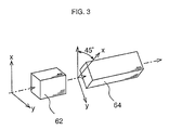
- a combiner which cannot maintain polarization is also applicable. If such a combiner is utilized, the depolarizing element 54 should be prepared as follows. That is, as shown in FIG. 3, birefringent mediums 62, 64 are connected in serial which polarization dispersions are longer than the coherence lengths of the output lights from the laser diodes 50a, 50b and in which one polarization dispersion differs more than twice as much as the other one.
- the two birefringent mediums 62 and 64 should be disposed so that the light passed through one polarization axis of the first located birefringent medium 62 is output from two polarization axes of the latter birefringent medium 64 at almost identical optical powers.
- transmission loss of the rutile crystal is uniform at every birefringent axis
- 10 mm rutile crystal and 20 mm rutile crystal should be disposed so that each birefringent axis is inclined at 45°.
- Birefringent mediums to be used as the depolarizing elements 34 and 54 are high birefringent optical fiber such as a PANDA fiber (a trademark) and YVO 4 besides the rutile crystal.
- the light source it is possible to use the light source to combine output lights from a plurality of pumping light sources at the same wavelength band in the orthogonal state of polarization and output them instead of the laser diode 50a.
- the laser diode 50b is also in the same situation.
- the depolarizing elements 34 and 54 are explained as depolarizing the input light, it is also possible that they only reduce the degree of polarization of the input light. The more the degree of polarization is reduced, the more the optical amplification characteristics is stabilized.
- the invention since a plurality of pumping lights are combined first and depolarized or weakly-polarized all at once, depolarized state of the pumping lights can be maintained even if one of the pumping light sources has failure.
- an optical amplifier e.g. a fiber Raman amplifier, which is highly reliable, economical and highly efficient is realized.
Landscapes
- Physics & Mathematics (AREA)
- Electromagnetism (AREA)
- Engineering & Computer Science (AREA)
- Plasma & Fusion (AREA)
- Optics & Photonics (AREA)
- Optical Modulation, Optical Deflection, Nonlinear Optics, Optical Demodulation, Optical Logic Elements (AREA)
- Lasers (AREA)
Applications Claiming Priority (2)
| Application Number | Priority Date | Filing Date | Title |
|---|---|---|---|
| JP2000182164 | 2000-06-16 | ||
| JP2000182164A JP2001356377A (ja) | 2000-06-16 | 2000-06-16 | ポンプ光発生装置及びファイバラマン増幅器 |
Publications (2)
| Publication Number | Publication Date |
|---|---|
| EP1164668A2 true EP1164668A2 (fr) | 2001-12-19 |
| EP1164668A3 EP1164668A3 (fr) | 2003-01-15 |
Family
ID=18682976
Family Applications (1)
| Application Number | Title | Priority Date | Filing Date |
|---|---|---|---|
| EP01114035A Withdrawn EP1164668A3 (fr) | 2000-06-16 | 2001-06-08 | Source de lumière de pompage et amplificateur Raman à fibre |
Country Status (3)
| Country | Link |
|---|---|
| US (1) | US6728437B2 (fr) |
| EP (1) | EP1164668A3 (fr) |
| JP (1) | JP2001356377A (fr) |
Cited By (5)
| Publication number | Priority date | Publication date | Assignee | Title |
|---|---|---|---|---|
| EP1229673A2 (fr) * | 2001-01-31 | 2002-08-07 | The Furukawa Electric Co., Ltd. | Amplificateur optique Raman avec source de pompage appropriée |
| EP1341324A1 (fr) * | 2002-02-21 | 2003-09-03 | Alcatel | Système de transmission à fibre optique utilisant l'amplification Raman |
| WO2004008206A1 (fr) * | 2002-07-12 | 2004-01-22 | Itf Technologies Optiques Inc.-Itf Optical Technologies Inc. | Depolariseur de conception lineaire tout-fibre |
| EP1437808A1 (fr) * | 2002-01-30 | 2004-07-14 | Mitsubishi Denki Kabushiki Kaisha | Dispositif de source lumineuse non polarisante et amplificateur raman |
| WO2012095641A1 (fr) * | 2011-01-11 | 2012-07-19 | Oclaro Technology Limited | Ensemble servant à multiplexer une lumière ayant différents états de polarisation et différentes longueurs d'onde |
Families Citing this family (20)
| Publication number | Priority date | Publication date | Assignee | Title |
|---|---|---|---|---|
| KR100325687B1 (ko) | 1999-12-21 | 2002-02-25 | 윤덕용 | 주입된 비간섭성 광에 파장 잠김된 페브리-페롯 레이저다이오드를 이용한 파장분할 다중방식 광통신용 광원 |
| CN1204662C (zh) | 2000-12-15 | 2005-06-01 | 古河电气工业株式会社 | 半导体激光器模块及其制造方法和光放大器 |
| DE60234795D1 (de) * | 2001-06-29 | 2010-02-04 | Sumitomo Electric Industries | Pumplichtquelleneinheit, Ramanverstärker und optisches Übertragungssystem |
| US6924926B2 (en) * | 2001-08-03 | 2005-08-02 | Xtera Communications, Inc. | Laser diode pump sources |
| US20030076579A1 (en) * | 2001-10-18 | 2003-04-24 | Dmitri Foursa | System and method for depolarizing optical amplifier pump surces |
| KR100955129B1 (ko) * | 2003-05-30 | 2010-04-28 | 정보통신연구진흥원 | 비간섭성 광대역 광원을 이용한 파장분할다중방식 수동형 광 네트워크 구현 방법 |
| KR100533914B1 (ko) * | 2003-10-08 | 2005-12-06 | 한국전자통신연구원 | 라만 증폭기 및 라만 펌핑 방법 |
| DE102006040858B8 (de) * | 2005-08-31 | 2018-03-08 | Zoller & Fröhlich GmbH | Sende-/Empfangsvorrichtung und Laserscanner |
| KR100698766B1 (ko) | 2005-09-07 | 2007-03-23 | 한국과학기술원 | 파장분할 다중방식 수동형 광 가입자 망 시스템에 사용되는장애 위치 감시 장치 및 이를 구비한 파장분할 다중방식수동형 광 가입자 망 시스템 |
| KR100785436B1 (ko) | 2005-09-20 | 2007-12-13 | 한국과학기술원 | 방송 서비스와 통신 서비스를 융합한 파장분할 다중방식수동형 광 가입자망 |
| CN100374953C (zh) * | 2005-10-11 | 2008-03-12 | 天津大学 | 分立式色散补偿型宽带光纤喇曼放大器 |
| CN100451802C (zh) * | 2005-10-11 | 2009-01-14 | 天津大学 | 宽带光纤喇曼放大器高效仿真方法 |
| US8571410B2 (en) | 2006-10-11 | 2013-10-29 | Novera Optics, Inc. | Mutual wavelength locking in WDM-PONS |
| JP2008306081A (ja) * | 2007-06-11 | 2008-12-18 | Miharu Communications Co Ltd | Mmpldを使用した光増幅方法と光増幅器 |
| JP2009260372A (ja) * | 2009-07-27 | 2009-11-05 | Miharu Communications Co Ltd | Mmpldを使用した光増幅方法と光増幅器 |
| GB2500220B (en) * | 2012-03-14 | 2018-03-14 | Ii Vi Laser Entpr Gmbh | A method and apparatus for depolarizing light |
| CN102621637B (zh) * | 2012-04-11 | 2014-02-26 | 珠海保税区光联通讯技术有限公司 | 晶体保偏光耦合器及其制造方法 |
| CN103368046B (zh) * | 2013-07-16 | 2015-09-16 | 中国电子科技集团公司第三十四研究所 | 线偏振激光输出高功率光纤放大器及输出控制方法 |
| CN103368047B (zh) * | 2013-07-16 | 2015-09-16 | 中国电子科技集团公司第三十四研究所 | 高功率线偏振激光输出光纤放大器及输出控制方法 |
| US9385504B2 (en) * | 2014-04-25 | 2016-07-05 | Ii-Vi Incorporated | Method and apparatus for depolarizing light |
Citations (3)
| Publication number | Priority date | Publication date | Assignee | Title |
|---|---|---|---|---|
| EP0734105A2 (fr) * | 1995-03-20 | 1996-09-25 | Fujitsu Limited | Amplificateur à fibre optique et module à fibre pour la compensation de la dispersion pour amplificateur à fibre optique |
| US5692082A (en) * | 1995-03-17 | 1997-11-25 | Fujitsu Limited | Laser diode module and depolarizer |
| EP1229673A2 (fr) * | 2001-01-31 | 2002-08-07 | The Furukawa Electric Co., Ltd. | Amplificateur optique Raman avec source de pompage appropriée |
Family Cites Families (15)
| Publication number | Priority date | Publication date | Assignee | Title |
|---|---|---|---|---|
| JPS57185410A (en) * | 1981-05-11 | 1982-11-15 | Kokusai Denshin Denwa Co Ltd <Kdd> | Optical coupler |
| JPS57190922A (en) | 1981-05-20 | 1982-11-24 | Nippon Telegr & Teleph Corp <Ntt> | Polarization eliminating circuit |
| JPS59155806A (ja) | 1983-02-24 | 1984-09-05 | Kokusai Denshin Denwa Co Ltd <Kdd> | 無偏光素子 |
| US4784450A (en) * | 1984-10-15 | 1988-11-15 | Hughes Aircraft Company | Apparatus for generating and amplifying new wavelengths of optical radiation |
| GB2179140B (en) * | 1985-08-14 | 1989-08-16 | Stc Plc | Sagnac effect device |
| GB2191357B (en) * | 1986-06-07 | 1990-04-25 | Stc Plc | Optical switching |
| JPH0727149B2 (ja) | 1986-11-04 | 1995-03-29 | 沖電気工業株式会社 | 光結合器 |
| JP2980751B2 (ja) * | 1991-10-09 | 1999-11-22 | キヤノン株式会社 | 光素子間光結合装置 |
| EP0768766B1 (fr) * | 1991-11-08 | 2001-07-04 | Mitsubishi Denki Kabushiki Kaisha | Système de répéteur avec amplificateurs à fibres optiques |
| JP3284507B2 (ja) * | 1993-06-28 | 2002-05-20 | 富士通株式会社 | 光通信システム用の光送信装置及び光増幅装置 |
| US5600738A (en) * | 1994-12-30 | 1997-02-04 | Lucent Technologies Inc. | Polarization dispersion compensation for optical devices |
| US5740288A (en) * | 1995-02-22 | 1998-04-14 | E-Tek Dynamics, Inc. | Variable polarization beam splitter, combiner and mixer |
| US6560015B1 (en) * | 1999-09-23 | 2003-05-06 | Avanex Corporation | High-isolation dense wavelength division multiplexer utilizing birefringent plates and a non-linear interferometer |
| JP2002107579A (ja) * | 2000-07-26 | 2002-04-10 | Furukawa Electric Co Ltd:The | 光合分波モジュール |
| US6522796B1 (en) * | 2000-10-24 | 2003-02-18 | Jds Uniphase Corporation | Depolarizing polarization mode combiner |
-
2000
- 2000-06-16 JP JP2000182164A patent/JP2001356377A/ja not_active Withdrawn
-
2001
- 2001-06-08 EP EP01114035A patent/EP1164668A3/fr not_active Withdrawn
- 2001-06-15 US US09/882,352 patent/US6728437B2/en not_active Expired - Fee Related
Patent Citations (3)
| Publication number | Priority date | Publication date | Assignee | Title |
|---|---|---|---|---|
| US5692082A (en) * | 1995-03-17 | 1997-11-25 | Fujitsu Limited | Laser diode module and depolarizer |
| EP0734105A2 (fr) * | 1995-03-20 | 1996-09-25 | Fujitsu Limited | Amplificateur à fibre optique et module à fibre pour la compensation de la dispersion pour amplificateur à fibre optique |
| EP1229673A2 (fr) * | 2001-01-31 | 2002-08-07 | The Furukawa Electric Co., Ltd. | Amplificateur optique Raman avec source de pompage appropriée |
Non-Patent Citations (1)
| Title |
|---|
| EMORI Y ET AL: "Cost-effective depolarized diode pump unit designed for C-band flat-gain Raman amplifiers to control EDFA gain profile" OPTICAL FIBER COMMUNICATION CONFERENCE. TECHNICAL DIGEST POSTCONFERENCE EDITION. TRENDS IN OPTICS AND PHOTONICS VOL.37 (IEEE CAT. NO. 00CH37079), OPTICAL FIBER COMMUNICATION CONFERENCE. TECHNICAL DIGEST POSTCONFERENCE EDITION. TRENDS IN OPTICS AND PH, pages 106-108 vol.4, XP002187327 2000, Washington, DC, USA, Opt. Soc. America, USA ISBN: 1-55752-630-3 * |
Cited By (11)
| Publication number | Priority date | Publication date | Assignee | Title |
|---|---|---|---|---|
| EP1229673A2 (fr) * | 2001-01-31 | 2002-08-07 | The Furukawa Electric Co., Ltd. | Amplificateur optique Raman avec source de pompage appropriée |
| EP1229673A3 (fr) * | 2001-01-31 | 2004-05-19 | The Furukawa Electric Co., Ltd. | Amplificateur optique Raman avec source de pompage appropriée |
| EP1562315A1 (fr) * | 2001-01-31 | 2005-08-10 | The Furukawa Electric Co., Ltd. | Amplificateur optique Raman avec source de pompage appropriée |
| EP1437808A1 (fr) * | 2002-01-30 | 2004-07-14 | Mitsubishi Denki Kabushiki Kaisha | Dispositif de source lumineuse non polarisante et amplificateur raman |
| EP1437808A4 (fr) * | 2002-01-30 | 2005-10-05 | Mitsubishi Electric Corp | Dispositif de source lumineuse non polarisante et amplificateur raman |
| US7218441B2 (en) | 2002-01-30 | 2007-05-15 | Mitsubishi Denki Kabushiki Kaisha | Non-polarization light source device and raman amplifier |
| EP1341324A1 (fr) * | 2002-02-21 | 2003-09-03 | Alcatel | Système de transmission à fibre optique utilisant l'amplification Raman |
| US6833947B2 (en) | 2002-02-21 | 2004-12-21 | Alcatel | Optical fiber transmission system |
| WO2004008206A1 (fr) * | 2002-07-12 | 2004-01-22 | Itf Technologies Optiques Inc.-Itf Optical Technologies Inc. | Depolariseur de conception lineaire tout-fibre |
| US6847744B2 (en) | 2002-07-12 | 2005-01-25 | Itf Technologies Optiques Inc. | All-fiber linear design depolarizer |
| WO2012095641A1 (fr) * | 2011-01-11 | 2012-07-19 | Oclaro Technology Limited | Ensemble servant à multiplexer une lumière ayant différents états de polarisation et différentes longueurs d'onde |
Also Published As
| Publication number | Publication date |
|---|---|
| JP2001356377A (ja) | 2001-12-26 |
| US6728437B2 (en) | 2004-04-27 |
| EP1164668A3 (fr) | 2003-01-15 |
| US20010053264A1 (en) | 2001-12-20 |
Similar Documents
| Publication | Publication Date | Title |
|---|---|---|
| US6728437B2 (en) | Pumping light generator and fiber Raman amplifier | |
| US6525872B1 (en) | Fiber grating-stabilized, semiconductor pump source | |
| US6549329B2 (en) | Multiple wavelength optical sources | |
| US6522796B1 (en) | Depolarizing polarization mode combiner | |
| US6049415A (en) | Polarization maintaining fiber lasers and amplifiers | |
| US6760151B1 (en) | Depolarized semiconductor laser sources | |
| JP2000098433A5 (fr) | ||
| EP1081813A2 (fr) | Amplificateur optique avec lumière de pompage dépolarisée | |
| US20020080833A1 (en) | Semiconductive laser module, laser unit, and Raman amplifier | |
| US6606337B1 (en) | Multiple band Raman amplifier pump source | |
| US6831778B2 (en) | Hybrid component and method for combining two pumping lights and depolarizing them simultaneously and optical amplifier therefor | |
| US20060109875A1 (en) | Depolarized laser diode module and depolarized laser diode light source | |
| JP2002229082A (ja) | ラマン光増幅用励起光源装置およびそれを用いたラマン光増幅システム | |
| US20020118715A1 (en) | Semiconductor laser module and Raman amplifier using the module | |
| US7218441B2 (en) | Non-polarization light source device and raman amplifier | |
| CN108139648A (zh) | 光放大器、光放大系统、波长变换器以及光通信系统 | |
| US6452720B1 (en) | Light source apparatus, optical amplifier and optical communication system | |
| JP3327148B2 (ja) | 光増幅器及びレーザ光発生装置 | |
| EP1241499A1 (fr) | Laser avec dépolariseur | |
| JP2001230480A (ja) | ラマン増幅利用の励起光源および光ファイバ通信システム | |
| EP1313182B1 (fr) | Syteme et méthode de depolarisation pour des sources à pompage optiques | |
| JPH11186639A (ja) | ポンプ光発生装置 | |
| JP4809554B2 (ja) | 半導体レーザモジュール及びこれを用いたラマン増幅器 | |
| JP2004014537A (ja) | 半導体レーザ装置、半導体レーザモジュールおよびこれを用いた光ファイバ増幅器 | |
| JP2004119653A (ja) | 広帯域ase光源 |
Legal Events
| Date | Code | Title | Description |
|---|---|---|---|
| PUAI | Public reference made under article 153(3) epc to a published international application that has entered the european phase |
Free format text: ORIGINAL CODE: 0009012 |
|
| AK | Designated contracting states |
Kind code of ref document: A2 Designated state(s): AT BE CH CY DE DK ES FI FR GB GR IE IT LI LU MC NL PT SE TR |
|
| AX | Request for extension of the european patent |
Free format text: AL;LT;LV;MK;RO;SI |
|
| PUAL | Search report despatched |
Free format text: ORIGINAL CODE: 0009013 |
|
| AK | Designated contracting states |
Kind code of ref document: A3 Designated state(s): AT BE CH CY DE DK ES FI FR GB GR IE IT LI LU MC NL PT SE TR |
|
| AX | Request for extension of the european patent |
Free format text: AL;LT;LV;MK;RO;SI |
|
| 17P | Request for examination filed |
Effective date: 20030625 |
|
| AKX | Designation fees paid |
Designated state(s): AT BE |
|
| RBV | Designated contracting states (corrected) |
Designated state(s): FR GB |
|
| REG | Reference to a national code |
Ref country code: DE Ref legal event code: 8566 |
|
| STAA | Information on the status of an ep patent application or granted ep patent |
Free format text: STATUS: THE APPLICATION HAS BEEN WITHDRAWN |
|
| 18W | Application withdrawn |
Effective date: 20050413 |