EP1164227A1 - Verankerungsvorrichtung für Betonbauteile - Google Patents
Verankerungsvorrichtung für Betonbauteile Download PDFInfo
- Publication number
- EP1164227A1 EP1164227A1 EP00111946A EP00111946A EP1164227A1 EP 1164227 A1 EP1164227 A1 EP 1164227A1 EP 00111946 A EP00111946 A EP 00111946A EP 00111946 A EP00111946 A EP 00111946A EP 1164227 A1 EP1164227 A1 EP 1164227A1
- Authority
- EP
- European Patent Office
- Prior art keywords
- section
- component
- shells
- engagement
- lateral wings
- Prior art date
- Legal status (The legal status is an assumption and is not a legal conclusion. Google has not performed a legal analysis and makes no representation as to the accuracy of the status listed.)
- Withdrawn
Links
- 238000004873 anchoring Methods 0.000 title claims abstract description 53
- 230000008878 coupling Effects 0.000 claims abstract description 60
- 238000010168 coupling process Methods 0.000 claims abstract description 60
- 238000005859 coupling reaction Methods 0.000 claims abstract description 60
- 229910052751 metal Inorganic materials 0.000 claims description 2
- 239000002184 metal Substances 0.000 claims description 2
- 238000004519 manufacturing process Methods 0.000 description 3
- 239000000463 material Substances 0.000 description 3
- 238000005452 bending Methods 0.000 description 2
- 238000000034 method Methods 0.000 description 2
- 229910000831 Steel Inorganic materials 0.000 description 1
- 229910052782 aluminium Inorganic materials 0.000 description 1
- XAGFODPZIPBFFR-UHFFFAOYSA-N aluminium Chemical compound [Al] XAGFODPZIPBFFR-UHFFFAOYSA-N 0.000 description 1
- 238000001125 extrusion Methods 0.000 description 1
- 230000000670 limiting effect Effects 0.000 description 1
- 238000012986 modification Methods 0.000 description 1
- 230000004048 modification Effects 0.000 description 1
- 230000003647 oxidation Effects 0.000 description 1
- 238000007254 oxidation reaction Methods 0.000 description 1
- 238000004806 packaging method and process Methods 0.000 description 1
- 230000001681 protective effect Effects 0.000 description 1
- 239000010959 steel Substances 0.000 description 1
- 239000000126 substance Substances 0.000 description 1
- 229920002994 synthetic fiber Polymers 0.000 description 1
- 239000011800 void material Substances 0.000 description 1
- 238000003466 welding Methods 0.000 description 1
Images


Classifications
-
- E—FIXED CONSTRUCTIONS
- E04—BUILDING
- E04F—FINISHING WORK ON BUILDINGS, e.g. STAIRS, FLOORS
- E04F13/00—Coverings or linings, e.g. for walls or ceilings
- E04F13/07—Coverings or linings, e.g. for walls or ceilings composed of covering or lining elements; Sub-structures therefor; Fastening means therefor
- E04F13/08—Coverings or linings, e.g. for walls or ceilings composed of covering or lining elements; Sub-structures therefor; Fastening means therefor composed of a plurality of similar covering or lining elements
- E04F13/0801—Separate fastening elements
- E04F13/0832—Separate fastening elements without load-supporting elongated furring elements between wall and covering elements
- E04F13/0853—Separate fastening elements without load-supporting elongated furring elements between wall and covering elements adjustable perpendicular to the wall
- E04F13/0855—Separate fastening elements without load-supporting elongated furring elements between wall and covering elements adjustable perpendicular to the wall adjustable in several directions, one of which is perpendicular to the wall
-
- E—FIXED CONSTRUCTIONS
- E04—BUILDING
- E04B—GENERAL BUILDING CONSTRUCTIONS; WALLS, e.g. PARTITIONS; ROOFS; FLOORS; CEILINGS; INSULATION OR OTHER PROTECTION OF BUILDINGS
- E04B1/00—Constructions in general; Structures which are not restricted either to walls, e.g. partitions, or floors or ceilings or roofs
- E04B1/38—Connections for building structures in general
- E04B1/41—Connecting devices specially adapted for embedding in concrete or masonry
-
- E—FIXED CONSTRUCTIONS
- E04—BUILDING
- E04F—FINISHING WORK ON BUILDINGS, e.g. STAIRS, FLOORS
- E04F13/00—Coverings or linings, e.g. for walls or ceilings
- E04F13/07—Coverings or linings, e.g. for walls or ceilings composed of covering or lining elements; Sub-structures therefor; Fastening means therefor
- E04F13/08—Coverings or linings, e.g. for walls or ceilings composed of covering or lining elements; Sub-structures therefor; Fastening means therefor composed of a plurality of similar covering or lining elements
- E04F13/0801—Separate fastening elements
- E04F13/0803—Separate fastening elements with load-supporting elongated furring elements between wall and covering elements
Definitions
- the present invention relates to a highly versatile anchoring device for components made of concrete or the like.
- the building method that uses prefabricated components entails the need to perform the on-site assembly of the components produced in the factory.
- This assembly can be of the wet type, performed for example by pouring additional concrete or by welding or chemical or mechanical anchoring, or of the dry type, performed by bolting.
- anchoring devices which use a basic component constituted by a section, commonly known as anchoring section, which is embedded in the concrete component during its production and is used to provide connection with other components by bolting.
- C-shaped hollow sections which are designed to be embedded substantially completely in the concrete component so that the open side of the C-shape is substantially co-planar to one face of the component, and sections which are again C-shaped and designed to be embedded substantially completely in the concrete so that the wing that connects the two arms of the C-shape is substantially co-planar with respect to a face of the component.
- the sections have a substantially C-shaped transverse cross-section with undercuts at the open side of the C-shape and are embedded substantially completely within the concrete component, so that the open side of the C-shape is arranged flush with one face of the component.
- the open side of the C-shape forms an open channel with undercuts and the shaped head of a bolt is arranged inside the channel and is engaged, following a partial rotation of the bolt about its own axis, with the undercuts formed at the edges of the channel. The bolt is then used to connect the component in which the section is embedded to another component.
- the head of the bolt can be arranged in any point of the extension of the channel, according to requirements, and therefore these anchoring devices allow "continuity of engagement" in the interconnection of the two components.
- the sections again have a substantially C-shaped transverse cross-section with two parallel wings joined by a connecting wing which is arranged at one face of the component.
- the two parallel wings are used to provide the stirrup arrangements for anchoring the section inside the component, and at least one slot is formed in the connecting wing and is elongated parallel to the longitudinal extension of the section; a bolt can engage the slot in order to connect the component to another component.
- these anchoring sections are meant to be embedded substantially completely inside the concrete component, they form, inside the component, a cavity which occupies space within the component and weakens it. Because of this, these sections are seldom usable in components which have a reduced thickness, in which the void formed by the anchoring section excessively compromises the resisting section of the component.
- the aim of the present invention is to solve the above-mentioned problems, by providing an anchoring device for components made of concrete or the like which does not penalize the resisting section of the component and allows "continuity of engagement" in the interconnection of two components.
- an object of the present invention is to provide an anchoring device which does not necessarily require the use of bolts and nuts of a particular type.
- Another object of the present invention is to provide an anchoring device which allows the greatest freedom in choosing the stirrup arrangement for anchoring within the component.
- Another object of the present invention is to provide an anchoring device which is very safe in the interconnection of two components.
- Another object of the present invention is to provide an anchoring device which does not require particular refinements in order to be embedded within a concrete component.
- Another object of the present invention is to provide an anchoring device which allows to adjust the connection between two components in two mutually perpendicular directions.
- an anchoring device for components made of concrete or the like, characterized in that it comprises an elongated section which is associable with a concrete component so as to protrude from said component with one of longitudinal sides thereof and with at least one portion of lateral faces thereof, which extend from said longitudinal side; engagement regions being provided on said portion of the lateral faces of the section and forming a plurality of possible engagement positions, mutually spaced along a longitudinal extension of the section, for a coupling element which is detachably associable with said portion of the section that protrudes from the component; said coupling element having at least one engagement region which forms a plurality of possible engagement positions, mutually spaced parallel to the longitudinal extension of the section, for an element for connecting said coupling element to another component or another element to be rigidly coupled to said component; the extension of said at least one engagement region for the connecting element in a direction which is parallel to the longitudinal extension of said section being at least equal to the maximum distance between two contiguous positions of possible engagement
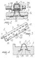
- the anchoring device generally designated by the reference numeral 1, comprises an elongated section 2 which is associable with a concrete component 3 so as to protrude from the component 3 with at least one of its longitudinal sides and with at least one portion of its lateral faces, which extend from said longitudinal side.
- Engagement regions 4 are formed in this portion of the lateral faces of the section 2 and form a plurality of possible engagement positions which are mutually spaced along the longitudinal extension of the section 2 for a coupling element 5 which is detachably associable with the portion of the section 2 that protrudes from the component 3.
- the coupling element 5 has at least one engagement region which forms a plurality of possible engagement positions, mutually spaced parallel to the longitudinal extension of the section 2, for a connecting element 6 which is adapted to connect the coupling element 5 to another component or other element to be rigidly coupled to the component 3.
- the extension, in a direction which is parallel to the longitudinal extension of the section 2, of the engagement region for the connecting element 6 provided on the coupling element 5 is at least equal to the maximum distance between two contiguous positions for possible engagement provided for the coupling element 5 along the section 2.
- the section 2 can be produced by bending steel plate or can be made of aluminum and produced for example by extrusion, or can be made of synthetic material or of another material according to requirements.
- the section 2 has two lateral wings 7 and 8 which face each other and form the two lateral faces of the section on which the engagement regions 4 for the coupling element 5 are provided.
- the two lateral wings 7 and 8 are preferably mutually joined, at one of their sides, by a flat portion 9 which constitutes the longitudinal side of the section 2 that protrudes from the component 3 and from which the two lateral wings 7 and 8 protrude.
- the lateral wings 7 and 8 preferably protrude along two inclined planes which converge toward the flat face 9.
- the section 2 has an open transverse cross-section in which the open region is meant to be associated with the component 3 or embedded therein, as will become apparent hereinafter.
- edges 10 and 11 that are directed away from the flat face 9 are folded outward.
- the edges 10 and 11 are preferably substantially co-planar.
- section 2 can be directly associated with a face of a component by means of its edges 10 and 11 by using screw anchors or other conventional connection means, it is preferably meant to be partially embedded within the body of the component 3, proximate to one of its faces, so as to protrude from said face of the component 3 with a portion of its lateral wings 7 and 8 that lies proximate to the flat face 9.
- the engagement regions 4 for the coupling element 5 are formed in said portion of the lateral wings 7 and 8 that is meant to protrude from the face of the component 3.
- Anchoring holes are formed in the portion of the section 2 that is instead meant to be embedded within the body of the component 3; such holes can be used to rigidly couple the anchoring stirrups to the section 2.
- the anchoring stirrup arrangements can be simply constituted by straight transverse rods 16 which are inserted through the holes 12.
- the anchoring stirrup arrangements can also be constituted by appropriately shaped strips 17 which are inserted through the holes 14.
- stirrup arrangements can be constituted by spirals 18 inserted through the holes 13.
- stirrup arrangements can also be constituted by stirrups 19 which are welded to the edges 10 and 11 of the lateral wings 7 and 8 of the section 2.
- the holes 15 formed in the edges 10 and 11 can be used to rigidly couple the section 2 to the component 3 by means of screw anchors.
- stirrup arrangements can be replaced or complemented by blanked and folded portions 20 so as to form lugs for anchoring in the component 3, at the portion of the section 2 that is meant to be embedded within the component 3.
- the engagement regions 4, formed in the portion of the lateral wings 7 and 8 of the section 2 that protrudes from the component 3, comprise a plurality of coupling holes 22 which are preferably rectangular and are uniformly mutually spaced along the longitudinal extension of the section 2.
- the holes 22 formed in the lateral wing 7 are aligned with the corresponding holes 22 formed in the other lateral wing 8 of the section 2.
- the coupling element 5 comprises two half-shells 23 and 24 which can be mutually coupled so as to straddle the longitudinal side of the section constituted by the flat face 9, so as to protrude transversely with one of their portions from the flat face 9.
- the half-shells 23 and 24 are provided with engagement means which can be coupled to the engagement regions 4 formed in the portion of the two lateral faces of the section 2 that protrudes from the component 3.
- the two half-shells 23 and 24 preferably have a box-like structure which is obtained by blanking and bending metal plate.
- the half-shells 23 and 24 comprise a first half-shell 23 which has, along one of its sides, at least one tab which can be inserted at least inside the coupling holes 22 provided in the lateral face 7, and a second half-shell 24 which has, along one of its sides, at least one tab which can be inserted at least inside the coupling holes 22 provided in the other lateral face 8.
- the first half-shell 23 is provided with two feet 23a and 23b which can be coupled to two contiguous coupling holes 22 of the lateral wing 7, and said feet 23a and 23b have a length which is preferably such as to also engage within the coupling holes 22 formed in the other lateral face 8.
- the other half-shell 24 has two feet 24a and 24b which can be inserted in two contiguous coupling holes 22 of the other lateral wing 8, and their length is such as to also engage the coupling holes 22 formed in the lateral wing 7.
- the coupling element 5 when the coupling element 5 is engaged with the section 2, its feet 23a, 23b and 24a, 24b occupy four coupling holes 22 which are mutually aligned in pairs and are formed in the two lateral wings 7 and 8. Each one of the coupling holes 22 is occupied by a tab 23a or 23b of the first half-shell 23 and by a tab 24a or 24b of the second half-shell 24 which are arranged side by side.
- the first half-shell 23 is shaped so as to at least partially enter, with its portion that protrudes from the flat face 9 of the section 2, into the corresponding portion of the second half-shell 24.
- the coupling element 5 is shaped so as to complementarily couple to the outer side of the portion of the section 2 that straddles the flat face 9 between the coupling holes 22 formed in the two lateral wings 7 and 8.
- the coupling element 5 has engaged the section 2, it has a portion which protrudes transversely from the extension of the section 2 on the side of the flat face 9.
- the engagement region for the connecting element 6 is formed on this portion of the coupling element 5, i.e., of the half-shells 23 and 24.
- the engagement region is constituted by a slot 30 which passes through the portion of the half-shells 23 and 24 that protrudes from the flat face 9 of the section 2; said slot 30 is elongated in a direction which is parallel to the longitudinal extension of the section 2.
- the extension of the region of the slot 30 that can be occupied by the connecting element 6 is greater than the center distance between the coupling holes 22 formed along the longitudinal extension of the section 2.
- the connecting element 6 can be constituted by a screw 32 provided with a threaded stem which is associable, by means of two nuts 33a and 33b, with the slot 30 formed in the half-shells 23 and 24 of the coupling element 5.
- the screw 32 can have, in a per se known manner, an appropriately shaped head 34 which can engage anchoring sections 39 of a known type which are embedded in the components 40 to be connected to the component 3, as shown in Figures 1 and 9.
- the connecting element 6 can be constituted by a threaded stem 32a which is folded at 90° and can engage, at its opposite ends, two coupling elements 5 of two anchoring devices according to the invention, in order to mutually connect two components 3 and 40 inside which a section 2 has been embedded as already described.
- the connecting element can also be constituted by a hook, or by an element having another shape according to requirements, which is provided with a threaded portion which can engage, by means of the bolts 33a and 33b, the coupling element 5 in order to rigidly couple to the component 3 other elements, such as for example channels, cables, pipes or other accessory elements for buildings, instead of another component.
- the use of the anchoring device according to the invention is as follows.
- the prefabricated components 3 for which connection to other components or other elements of the building is required are formed beforehand by partially embedding a section 2 of preset length proximate to one of the faces of the component 3, so that the section 2 protrudes, with a portion of its lateral wings 7 and 8, proximate to the flat face 9, from one face of the component 3, optionally even at recessed regions formed in the face of the component so as to still allow the portion of the section that is provided with the coupling holes 22 to protrude from a region of the component 3 without necessarily protruding from the overall dimensions of the component 3, as shown in particular in Figure 11.
- section 2 can be applied to a face of the component 3, for example by means of expanding screw anchors or other fixing systems.
- the two half-shells 23 and 24 of the coupling element 5 are assembled to the portion of the section 2 that protrudes from the component by inserting the feet 23a and 23b, 24a and 24b in two contiguous coupling holes 22, or rather inside four coupling holes 22 which are mutually aligned in pairs, by way of a mutual approach of the two half-shells 23 and 24 in a direction which lies transversely to the longitudinal extension of the section 2.
- the position of the threaded stem of the connecting element 6 inside the slot 30 can be changed according to requirements.
- the connecting element 6 is rigidly coupled to another component 40, as shown in Figures 9 to 11, or to other elements to be connected to the component 3.
- section 2 does not have the blanked and folded portions 20, owing to its particular configuration it can also be stacked with other identical sections, thus achieving the advantage of occupying a small space during packaging and shipping.
- the anchoring device according to the invention fully achieves the intended aim and objects, since it does not reduce the resisting section of the component inside which it is embedded or with which it is associated, although allowing "continuity of engagement" in the connection between two components or between a component and other elements.
- Another advantage of the anchoring device according to the invention is that it does not necessarily require the use of sponges or other elements to protect the cavity of the section during the production of the component.
- Another advantage of the anchoring device according to the invention is that it leaves great freedom of choice as regards the anchoring stirrup arrangements inside the component and the greatest freedom of choice as regards the bolts and nuts for anchoring.
- the materials used, as well as the dimensions, may be any according to requirements and to the state of the art.
Landscapes
- Engineering & Computer Science (AREA)
- Architecture (AREA)
- Civil Engineering (AREA)
- Structural Engineering (AREA)
- Physics & Mathematics (AREA)
- Electromagnetism (AREA)
- Joining Of Building Structures In Genera (AREA)
Priority Applications (2)
| Application Number | Priority Date | Filing Date | Title |
|---|---|---|---|
| EP00111946A EP1164227A1 (de) | 2000-06-15 | 2000-06-15 | Verankerungsvorrichtung für Betonbauteile |
| US09/594,818 US6502362B1 (en) | 2000-06-15 | 2000-06-16 | Anchoring device for components made of concrete |
Applications Claiming Priority (2)
| Application Number | Priority Date | Filing Date | Title |
|---|---|---|---|
| EP00111946A EP1164227A1 (de) | 2000-06-15 | 2000-06-15 | Verankerungsvorrichtung für Betonbauteile |
| US09/594,818 US6502362B1 (en) | 2000-06-15 | 2000-06-16 | Anchoring device for components made of concrete |
Publications (1)
| Publication Number | Publication Date |
|---|---|
| EP1164227A1 true EP1164227A1 (de) | 2001-12-19 |
Family
ID=26071019
Family Applications (1)
| Application Number | Title | Priority Date | Filing Date |
|---|---|---|---|
| EP00111946A Withdrawn EP1164227A1 (de) | 2000-06-15 | 2000-06-15 | Verankerungsvorrichtung für Betonbauteile |
Country Status (2)
| Country | Link |
|---|---|
| US (1) | US6502362B1 (de) |
| EP (1) | EP1164227A1 (de) |
Cited By (6)
| Publication number | Priority date | Publication date | Assignee | Title |
|---|---|---|---|---|
| WO2004035952A1 (en) * | 2002-10-16 | 2004-04-29 | Timberfix Limited | Construction system |
| WO2004053255A1 (es) * | 2002-12-11 | 2004-06-24 | Adell Argiles Josep Maria | Sistema de apoyo para muros de albañilería |
| DE102005057015A1 (de) * | 2005-11-30 | 2007-06-06 | Hering Bau Gmbh & Co. Kg | Fassadenelement und dessen Verwendung |
| EP1764448A3 (de) * | 2005-09-16 | 2008-08-06 | Laing O'Rourke Plc | Verbindungsvorrichtungen zum Einbetonieren |
| USD910207S1 (en) | 2013-10-22 | 2021-02-09 | Certainteed Corporation | Manufactured siding panel with frame |
| US11047134B2 (en) * | 2012-10-24 | 2021-06-29 | Certainteed Llc | Manufactured building panel |
Families Citing this family (36)
| Publication number | Priority date | Publication date | Assignee | Title |
|---|---|---|---|---|
| US6658810B2 (en) * | 2002-03-27 | 2003-12-09 | Deloach, Sr. W. Michael | Tilt-up concrete wall panel form and method of fabricating same |
| US7171788B2 (en) * | 2002-04-05 | 2007-02-06 | Joseph Bronner | Masonry connectors and twist-on hook and method |
| US6837013B2 (en) * | 2002-10-08 | 2005-01-04 | Joel Foderberg | Lightweight precast concrete wall panel system |
| US20040231270A1 (en) * | 2003-05-22 | 2004-11-25 | Collins P. Michael | Masonry tie for cavity wall construction |
| US20050279043A1 (en) * | 2004-06-18 | 2005-12-22 | Joseph Bronner | Wall anchor system and method |
| US7509777B2 (en) * | 2004-06-28 | 2009-03-31 | Spancrete Machinery Corporation | Base connection for connecting a concrete wall panel to a foundation |
| US20060236627A1 (en) * | 2005-04-01 | 2006-10-26 | Messenger Harold G | Combination lift and anchor connector for fabricated wall and floor panels |
| DE102005030332A1 (de) * | 2005-06-29 | 2007-01-04 | Peri Gmbh | Angelenkter Kletterschuh einer Kletterschalung |
| KR100978960B1 (ko) * | 2007-10-29 | 2010-08-30 | 현대엔지니어링 주식회사 | 2차부재 고정용 강판절곡 매입기구 |
| ES2338192B1 (es) * | 2007-12-13 | 2011-03-28 | Eclad Limited | Sistema de anclaje de fachadas ventiladas. |
| CA2667858A1 (en) * | 2008-08-13 | 2010-02-13 | Joseph Bronner | Side mounted drill bolt and threaded anchor system for veneer wall tie connection |
| KR100910362B1 (ko) | 2009-04-22 | 2009-08-04 | 주식회사 태하엔지니어링건축사사무소 | Pc판넬을 이용한 공간쌓기 공법 |
| US8966834B2 (en) * | 2009-07-17 | 2015-03-03 | Robert Sladojevic | Concrete lifting anchors |
| CA2803405A1 (en) * | 2009-07-17 | 2011-01-20 | Casne Verige Pty Ltd | Concrete lifting anchors |
| US8544228B2 (en) * | 2009-10-27 | 2013-10-01 | Joseph Bronner | Winged anchor and spiked spacer for veneer wall tie connection system and method |
| US8555587B2 (en) * | 2010-05-11 | 2013-10-15 | Mitek Holdings, Inc. | Restoration anchoring system |
| AU2010273164B2 (en) * | 2010-06-30 | 2016-10-20 | Pre-Form Systems Doo | Concrete lifting anchors |
| US8973334B2 (en) | 2010-12-06 | 2015-03-10 | Scott Croasdale | System and methods for thermal isolation of components used |
| WO2012119239A1 (en) | 2011-03-09 | 2012-09-13 | Quadrosera Corporation | Clips for thin brick wall system |
| US8596010B2 (en) * | 2011-05-20 | 2013-12-03 | Mitek Holdings, Inc. | Anchor with angular adjustment |
| US8555596B2 (en) | 2011-05-31 | 2013-10-15 | Mitek Holdings, Inc. | Dual seal tubular anchor for cavity walls |
| US8516763B2 (en) * | 2011-06-02 | 2013-08-27 | Mitek Holdings, Inc. | Thermally isolating tubule for wall anchor |
| US8800241B2 (en) | 2012-03-21 | 2014-08-12 | Mitek Holdings, Inc. | Backup wall reinforcement with T-type anchor |
| US8661766B2 (en) | 2012-06-22 | 2014-03-04 | Mitek Holdings, Inc. | Anchor with angular adjustment |
| USD706127S1 (en) | 2012-07-26 | 2014-06-03 | Mitek Holdings, Inc. | Wing nut anchor having discontinuous threads |
| USD702544S1 (en) | 2012-07-26 | 2014-04-15 | Mitek Holdings, Inc. | Thermal wing nut anchor having continuous threads |
| US8789339B2 (en) * | 2012-12-20 | 2014-07-29 | Tecnodima S.R.L. | Method for making façades of buildings |
| CA2820970C (en) * | 2013-03-14 | 2020-09-15 | Douglas James Knight | Improved modular system for continuously insulating exterior walls of a structure and securing exterior cladding to the structure |
| FR3019201B1 (fr) * | 2014-03-28 | 2016-05-06 | Louis Boschian | Dispositif de fixation d'elements d'habillage sur une lambourde |
| KR101543683B1 (ko) * | 2015-05-26 | 2015-08-11 | 주식회사 동건 | 단열재모듈 및 이를 이용한 단열벽구조 및 이를 이용한 단열벽 시공방법 |
| US10407892B2 (en) | 2015-09-17 | 2019-09-10 | Columbia Insurance Company | High-strength partition top anchor and anchoring system utilizing the same |
| USD846973S1 (en) | 2015-09-17 | 2019-04-30 | Columbia Insurance Company | High-strength partition top anchor |
| US20170159285A1 (en) | 2015-12-04 | 2017-06-08 | Columbia Insurance Company | Thermal wall anchor |
| US10729257B1 (en) | 2016-06-06 | 2020-08-04 | Jamie S. Leach | Infant nursing pillow |
| US11725413B2 (en) * | 2020-07-17 | 2023-08-15 | Granite Industries, Inc. | Elevated flooring system for clearspan tent |
| US11959270B1 (en) * | 2021-04-16 | 2024-04-16 | Morse Distribution, Inc. | Stud rail systems and methods for use in reinforced concrete structures |
Citations (4)
| Publication number | Priority date | Publication date | Assignee | Title |
|---|---|---|---|---|
| US4060951A (en) * | 1976-09-15 | 1977-12-06 | Sandor Gere | Stressless suspension and anchoring process of stone veneer |
| DE2916003A1 (de) * | 1979-04-20 | 1980-10-23 | Fricker Frimeda Metall Draht | Befestigungsvorrichtung, insbesondere fuer die verbindung von zwei bauteilen von bauwerken |
| GB2047375A (en) * | 1979-04-12 | 1980-11-26 | Campbell P | Fixing device for securing cladding panels to walls |
| DE19725882A1 (de) * | 1997-06-18 | 1998-12-24 | Modersohn Gmbh & Co Kg Wilh | Ankerschiene |
Family Cites Families (5)
| Publication number | Priority date | Publication date | Assignee | Title |
|---|---|---|---|---|
| US5207043A (en) * | 1988-11-07 | 1993-05-04 | Mcgee Brian P | Masonry connector |
| US4955172A (en) * | 1989-09-14 | 1990-09-11 | Pierson Neil W | Veneer anchor |
| US5454200A (en) * | 1993-11-04 | 1995-10-03 | Hohmann; Ronald P. | Veneer anchoring system |
| US5392581A (en) * | 1993-11-08 | 1995-02-28 | Fero Holdings Ltd. | Masonry connector |
| CA2136700C (en) * | 1994-11-25 | 2005-06-28 | William Scott Burns | Adjustable wall tie |
-
2000
- 2000-06-15 EP EP00111946A patent/EP1164227A1/de not_active Withdrawn
- 2000-06-16 US US09/594,818 patent/US6502362B1/en not_active Expired - Fee Related
Patent Citations (4)
| Publication number | Priority date | Publication date | Assignee | Title |
|---|---|---|---|---|
| US4060951A (en) * | 1976-09-15 | 1977-12-06 | Sandor Gere | Stressless suspension and anchoring process of stone veneer |
| GB2047375A (en) * | 1979-04-12 | 1980-11-26 | Campbell P | Fixing device for securing cladding panels to walls |
| DE2916003A1 (de) * | 1979-04-20 | 1980-10-23 | Fricker Frimeda Metall Draht | Befestigungsvorrichtung, insbesondere fuer die verbindung von zwei bauteilen von bauwerken |
| DE19725882A1 (de) * | 1997-06-18 | 1998-12-24 | Modersohn Gmbh & Co Kg Wilh | Ankerschiene |
Cited By (10)
| Publication number | Priority date | Publication date | Assignee | Title |
|---|---|---|---|---|
| WO2004035952A1 (en) * | 2002-10-16 | 2004-04-29 | Timberfix Limited | Construction system |
| WO2004053255A1 (es) * | 2002-12-11 | 2004-06-24 | Adell Argiles Josep Maria | Sistema de apoyo para muros de albañilería |
| ES2221785A1 (es) * | 2002-12-11 | 2005-01-01 | Josep Maria Adell Argiles | Sistema de apoyo para muros de albañileria. |
| EP1764448A3 (de) * | 2005-09-16 | 2008-08-06 | Laing O'Rourke Plc | Verbindungsvorrichtungen zum Einbetonieren |
| DE102005057015A1 (de) * | 2005-11-30 | 2007-06-06 | Hering Bau Gmbh & Co. Kg | Fassadenelement und dessen Verwendung |
| DE102005057015A8 (de) * | 2005-11-30 | 2007-09-20 | Hering Bau Gmbh & Co. Kg | Fassadenelement und dessen Verwendung |
| EP1793062A3 (de) * | 2005-11-30 | 2008-06-25 | Hering Bau GmbH & Co. KG | Fassadenelement und dessen verwendung |
| US11047134B2 (en) * | 2012-10-24 | 2021-06-29 | Certainteed Llc | Manufactured building panel |
| US11828071B2 (en) | 2012-10-24 | 2023-11-28 | Certainteed Llc | Manufactured building panel assembly |
| USD910207S1 (en) | 2013-10-22 | 2021-02-09 | Certainteed Corporation | Manufactured siding panel with frame |
Also Published As
| Publication number | Publication date |
|---|---|
| US6502362B1 (en) | 2003-01-07 |
Similar Documents
| Publication | Publication Date | Title |
|---|---|---|
| US6502362B1 (en) | Anchoring device for components made of concrete | |
| KR100763634B1 (ko) | 전단보강용 와이어로프를 이용한 구조물 전단 및 내진보강 | |
| KR200445056Y1 (ko) | 파이프 이격기능이 구비된 파이프 체결 어셈블리 | |
| KR100897341B1 (ko) | 판형 회전방지구가 적용된 부스 덕트 연결용 조인트 키트 | |
| KR200444873Y1 (ko) | 벽체시공용 거푸집 지지구 | |
| KR100633014B1 (ko) | 흙막이 구조물의 앵커 지지체 및 이를 구비한 띠장 | |
| JP5620148B2 (ja) | 連結具 | |
| KR200345121Y1 (ko) | 건축공사용 파이프 비계의 미끄럼 방지 체결구조 | |
| JPH08184096A (ja) | グレーチングの連結構造 | |
| JPH067169Y2 (ja) | 構築用止水板支持金具 | |
| KR200239503Y1 (ko) | 조립식 암거 | |
| KR200242782Y1 (ko) | 철근 연결구 | |
| KR200236765Y1 (ko) | 조립식암거 | |
| KR200189738Y1 (ko) | 창문틀의 코너 체결구조 | |
| KR19980020421U (ko) | 철근 연결 장치 | |
| CN220353090U (zh) | 预埋件及预应力混凝土空心楼板 | |
| ITMI982764A1 (it) | Dispositivo di ancoraggio per manufatti in calcestruzzo o simili, adelevata versatilita' di impiego. | |
| KR20180113776A (ko) | 조인트 클립이 결합된 프로파일 어셈블리 및 프로파일 어셈블리 결합용 조인트 클립 | |
| KR200246496Y1 (ko) | 콘크리트 작업용 철근연결구 | |
| JPH0115737Y2 (de) | ||
| KR200203052Y1 (ko) | 닥트용 행거 장치 | |
| JP2817034B2 (ja) | デッキプレート用ケーブル支持具 | |
| KR200222080Y1 (ko) | 지중전력구의 방재트로후 받침 행거 | |
| KR200223959Y1 (ko) | 매입형 전기배선박스의 고정구 | |
| KR200304660Y1 (ko) | 커튼 월 고정장치의 장착구조 |
Legal Events
| Date | Code | Title | Description |
|---|---|---|---|
| PUAI | Public reference made under article 153(3) epc to a published international application that has entered the european phase |
Free format text: ORIGINAL CODE: 0009012 |
|
| AK | Designated contracting states |
Kind code of ref document: A1 Designated state(s): AT BE CH CY DE DK ES FI FR GB GR IE IT LI LU MC NL PT SE Kind code of ref document: A1 Designated state(s): AT BE CH CY DE DK ES FI FR GB GR IE LI LU MC NL PT SE |
|
| AX | Request for extension of the european patent |
Free format text: AL;LT;LV;MK;RO;SI |
|
| 17P | Request for examination filed |
Effective date: 20020523 |
|
| AKX | Designation fees paid |
Free format text: AT BE CH CY DE DK ES FI FR GB GR IE LI LU MC NL PT SE |
|
| 17Q | First examination report despatched |
Effective date: 20080714 |
|
| STAA | Information on the status of an ep patent application or granted ep patent |
Free format text: STATUS: THE APPLICATION IS DEEMED TO BE WITHDRAWN |
|
| 18D | Application deemed to be withdrawn |
Effective date: 20081125 |