EP1163985A1 - Handflansch einer Roboterhand mit einem Anbauteil zur Aufnahme eines Hilfgeräts - Google Patents
Handflansch einer Roboterhand mit einem Anbauteil zur Aufnahme eines Hilfgeräts Download PDFInfo
- Publication number
- EP1163985A1 EP1163985A1 EP01112425A EP01112425A EP1163985A1 EP 1163985 A1 EP1163985 A1 EP 1163985A1 EP 01112425 A EP01112425 A EP 01112425A EP 01112425 A EP01112425 A EP 01112425A EP 1163985 A1 EP1163985 A1 EP 1163985A1
- Authority
- EP
- European Patent Office
- Prior art keywords
- hand flange
- attachment
- hand
- flange according
- fastening ring
- Prior art date
- Legal status (The legal status is an assumption and is not a legal conclusion. Google has not performed a legal analysis and makes no representation as to the accuracy of the status listed.)
- Granted
Links
Images

Classifications
-
- B—PERFORMING OPERATIONS; TRANSPORTING
- B25—HAND TOOLS; PORTABLE POWER-DRIVEN TOOLS; MANIPULATORS
- B25J—MANIPULATORS; CHAMBERS PROVIDED WITH MANIPULATION DEVICES
- B25J19/00—Accessories fitted to manipulators, e.g. for monitoring, for viewing; Safety devices combined with or specially adapted for use in connection with manipulators
- B25J19/02—Sensing devices
-
- B—PERFORMING OPERATIONS; TRANSPORTING
- B25—HAND TOOLS; PORTABLE POWER-DRIVEN TOOLS; MANIPULATORS
- B25J—MANIPULATORS; CHAMBERS PROVIDED WITH MANIPULATION DEVICES
- B25J15/00—Gripping heads and other end effectors
- B25J15/04—Gripping heads and other end effectors with provision for the remote detachment or exchange of the head or parts thereof
-
- B—PERFORMING OPERATIONS; TRANSPORTING
- B25—HAND TOOLS; PORTABLE POWER-DRIVEN TOOLS; MANIPULATORS
- B25J—MANIPULATORS; CHAMBERS PROVIDED WITH MANIPULATION DEVICES
- B25J19/00—Accessories fitted to manipulators, e.g. for monitoring, for viewing; Safety devices combined with or specially adapted for use in connection with manipulators
Definitions
- the invention relates to a hand flange of a robot hand.
- Measuring body which is from a separate sensor, with which positions on a workpiece are measured, under appear within a certain limited angular range should, so that the measuring body is reproducible and known Way must be adjustable.
- the invention is therefore based on the object of a hand flange to train a type of robot in such a way that under Avoiding the aforementioned disadvantages of auxiliary devices reproducible and relative to known positions can be determined by himself.
- the stated object is achieved with a hand flange a robot hand released by an attachment for Recording an auxiliary device, such as a measuring body, one Sensor, an additional or auxiliary tool.
- an auxiliary device such as a measuring body, one Sensor, an additional or auxiliary tool.
- the assembly and disassembly of the auxiliary device in a certain Position but also in different but predetermined Positions can be reproduced in a time-saving manner by using from the start on a predetermined, in particular axially fixed Position an attachment that carries the auxiliary device, fixed is.
- auxiliary device is detachably attached to the hand flange.
- the attachment as Fastening ring is formed.
- Another preferred Embodiment of the invention provides that it has a circumferential groove has, in which the attachment is held.
- the advantage of the invention is mainly the elimination of the measurement effort, since the connecting devices on Ring calibrated connection dimensions in relation to the hand flange exhibit. If a device is attached, its point of action or line - with an optical sensor like one CCD camera these are the optical axis and the image plane - An already known position compared to the mounting device (Screwing surface, screw holes, profile foot etc.), a measurement is unnecessary. This is of particular weight with frequent exchanges.
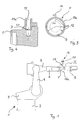
- the robot 1 designed according to the invention has the usual ones essential mechanical parts on: base 2, carousel 3, swing arm 4, robot arm 5, hand 6 with hand flange 7, to which a tool 8 in the form of a welding gun is attached is.
- the inventive hand flange 7 has one Circumferential groove 9 in which an attachment 11 with a mounting ring 11a is arranged.
- the mounting ring 11 is inevitably divisible or open for assembly / disassembly.
- the mounting ring 11a is through holes 12 at the bottom of the Groove 9 of the hand flange 7 fixed to this.
- the mounting ring 11a is designed here as a hinged clamp (Fig. 2).
- the mounting ring 11a has a bore 13 for receiving a plug part 14 of an auxiliary device 15, such as a measuring body a sensor or an additional or alternative tool to the actual tool 8.
- an auxiliary device 15 such as a measuring body a sensor or an additional or alternative tool to the actual tool 8.
- the mounting ring 11a is basically rotatable.
- the fixation takes place in a certain angular position by staking out using a pin, such as the plug-in part 14, which is inserted radially through a bore 13 in the ring and in a (determining the angular position) bore 12 in Hand flange 7 immersed.
- the stakeout can be both done manually as well as by resilient mounting of the pen 14 in the ring 11a, the pin 14 upon rotation of the Rings 11a automatically into the next hole in the hand flange 7 dives.
- the ring is fastened by screws not instead.
Landscapes
- Engineering & Computer Science (AREA)
- Robotics (AREA)
- Mechanical Engineering (AREA)
- Manipulator (AREA)
Abstract
Description
- Fig. 1
- einen Roboter mit einem erfindungsgemäß ausgebildeten Handflansch in Seitenansicht;
- Fig. 2
- eine perspektivische Gesamtdarstellung eines Anbauteils mit einem Hilfsgerät in Form eines Meßkörpers
- Fig. 3
- eine vergrößerte Darstellung des Bereichs II der Fig. 1;
- Fig. 4
- Fig. 3 einen Schnitt entsprechend A-A der Fig. 2.
- 1
- Roboter
- 2
- Sockel
- 3
- Karussell
- 4
- Schwinge
- 5
- Roboterarm
- 6
- Hand
- 7
- Handflansch
- 8
- Werkzeug
- 9
- Umfangsnut
- 11
- Befestigungsring
- 12
- Bohrungen
- 13
- Bohrung
- 14
- Steckteil
- 15
- Hilfsgerät
Claims (10)
- Handflansch einer Roboterhand, gekennzeichnet durch ein Anbauteil zur Aufnahme eines Hilfsgeräts (18), wie eines Messkörpers, eines Sensors, eines Zusatz- oder Hilfswerkzeugs.
- Handflansch nach Anspruch 1, dadurch gekennzeichnet, dass das Hilfsgerät (18) lösbar am Handflansch (7) befestigt ist.
- Handflansch nach Anspruch 1 oder 2, dadurch gekennzeichnet, dass das Anbauteil (11) einen Befestigungsring (17a) aufweist.
- Handflansch nach einem der vorangehenden Ansprüche, dadurch gekennzeichnet, dass er eine Umfangsnut (9) aufweist, in der das Anbauteil (11) gehalten ist.
- Handflansch nach Anspruch 4, gekennzeichnet durch einen inneren Ringvorsprung (11b) am Befestigungsring (11a) der mit der Umfangsnut (9) eine Nut-Faden-Verbindung bildet.
- Handflansch nach einem der Ansprüche 3 bis 5, dadurch gekennzeichnet, dass der Befestigungsring (11a) teilbar bzw. zu öffnen ist.
- Handflansch nach Anspruch 6, dadurch gekennzeichnet, dass der Befestigungsring als Klappschelle ausgebildet ist.
- Handflansch nach einem der Ansprüche 1 bis 7, dadurch gekennzeichnet, dass an seinem Umfang eine Vielzahl von Bohrungen (12) zur drehfesten Verlagerung des Anbauteils (11) vorgesehen sind.
- Handflansch nach Anspruch 6, dadurch gekennzeichnet, dass die Fixierung des Anbauteils (11) in eine bestimmte Winkelstellung durch Hindurchstecken eines Stiftes (14) in eine der Bohrungen (12) erfolgt.
- Handflansch nach Anspruch 7, dadurch gekennzeichnet, dass der Stift (14) am Anbauteil (11) unter radial nach innen wirkender Federkraft elastisch gelagert ist.
Applications Claiming Priority (2)
| Application Number | Priority Date | Filing Date | Title |
|---|---|---|---|
| DE20009543U | 2000-05-27 | ||
| DE20009543U DE20009543U1 (de) | 2000-05-27 | 2000-05-27 | Handflansch einer Roboterhand |
Publications (2)
| Publication Number | Publication Date |
|---|---|
| EP1163985A1 true EP1163985A1 (de) | 2001-12-19 |
| EP1163985B1 EP1163985B1 (de) | 2008-07-30 |
Family
ID=7942109
Family Applications (1)
| Application Number | Title | Priority Date | Filing Date |
|---|---|---|---|
| EP01112425A Expired - Lifetime EP1163985B1 (de) | 2000-05-27 | 2001-05-22 | Handflansch einer Roboterhand mit einem Anbauteil zur Aufnahme eines Hilfgeräts |
Country Status (3)
| Country | Link |
|---|---|
| US (1) | US20010045808A1 (de) |
| EP (1) | EP1163985B1 (de) |
| DE (2) | DE20009543U1 (de) |
Cited By (1)
| Publication number | Priority date | Publication date | Assignee | Title |
|---|---|---|---|---|
| FR2881072A1 (fr) * | 2005-01-26 | 2006-07-28 | Cimlec Ind Sa | Dispositif de guidage d'un faisceau d'alimentation d'organe terminal effecteur |
Families Citing this family (46)
| Publication number | Priority date | Publication date | Assignee | Title |
|---|---|---|---|---|
| US7001138B2 (en) * | 2002-03-01 | 2006-02-21 | Johnson & Johnson Vision Care, Inc. | Split collar for mechanical arm connection |
| JP2005138223A (ja) * | 2003-11-06 | 2005-06-02 | Fanuc Ltd | ロボット用位置データ修正装置 |
| US9937577B2 (en) | 2006-12-20 | 2018-04-10 | Lincoln Global, Inc. | System for a welding sequencer |
| US9104195B2 (en) | 2006-12-20 | 2015-08-11 | Lincoln Global, Inc. | Welding job sequencer |
| US10994358B2 (en) | 2006-12-20 | 2021-05-04 | Lincoln Global, Inc. | System and method for creating or modifying a welding sequence based on non-real world weld data |
| US9483959B2 (en) | 2008-08-21 | 2016-11-01 | Lincoln Global, Inc. | Welding simulator |
| US8834168B2 (en) | 2008-08-21 | 2014-09-16 | Lincoln Global, Inc. | System and method providing combined virtual reality arc welding and three-dimensional (3D) viewing |
| US9196169B2 (en) | 2008-08-21 | 2015-11-24 | Lincoln Global, Inc. | Importing and analyzing external data using a virtual reality welding system |
| US8911237B2 (en) | 2008-08-21 | 2014-12-16 | Lincoln Global, Inc. | Virtual reality pipe welding simulator and setup |
| US8851896B2 (en) | 2008-08-21 | 2014-10-07 | Lincoln Global, Inc. | Virtual reality GTAW and pipe welding simulator and setup |
| US8747116B2 (en) | 2008-08-21 | 2014-06-10 | Lincoln Global, Inc. | System and method providing arc welding training in a real-time simulated virtual reality environment using real-time weld puddle feedback |
| US9330575B2 (en) | 2008-08-21 | 2016-05-03 | Lincoln Global, Inc. | Tablet-based welding simulator |
| US8915740B2 (en) | 2008-08-21 | 2014-12-23 | Lincoln Global, Inc. | Virtual reality pipe welding simulator |
| US9280913B2 (en) | 2009-07-10 | 2016-03-08 | Lincoln Global, Inc. | Systems and methods providing enhanced education and training in a virtual reality environment |
| US9318026B2 (en) | 2008-08-21 | 2016-04-19 | Lincoln Global, Inc. | Systems and methods providing an enhanced user experience in a real-time simulated virtual reality welding environment |
| US8884177B2 (en) | 2009-11-13 | 2014-11-11 | Lincoln Global, Inc. | Systems, methods, and apparatuses for monitoring weld quality |
| US8657605B2 (en) * | 2009-07-10 | 2014-02-25 | Lincoln Global, Inc. | Virtual testing and inspection of a virtual weldment |
| US8274013B2 (en) | 2009-03-09 | 2012-09-25 | Lincoln Global, Inc. | System for tracking and analyzing welding activity |
| US9221117B2 (en) | 2009-07-08 | 2015-12-29 | Lincoln Global, Inc. | System for characterizing manual welding operations |
| US9773429B2 (en) | 2009-07-08 | 2017-09-26 | Lincoln Global, Inc. | System and method for manual welder training |
| US9011154B2 (en) | 2009-07-10 | 2015-04-21 | Lincoln Global, Inc. | Virtual welding system |
| US10748447B2 (en) | 2013-05-24 | 2020-08-18 | Lincoln Global, Inc. | Systems and methods providing a computerized eyewear device to aid in welding |
| US8569655B2 (en) | 2009-10-13 | 2013-10-29 | Lincoln Global, Inc. | Welding helmet with integral user interface |
| US8569646B2 (en) | 2009-11-13 | 2013-10-29 | Lincoln Global, Inc. | Systems, methods, and apparatuses for monitoring weld quality |
| US9468988B2 (en) | 2009-11-13 | 2016-10-18 | Lincoln Global, Inc. | Systems, methods, and apparatuses for monitoring weld quality |
| CA2821671C (en) | 2010-12-13 | 2018-01-09 | Edison Welding Institute, Inc. | Welding training system |
| US20160093233A1 (en) | 2012-07-06 | 2016-03-31 | Lincoln Global, Inc. | System for characterizing manual welding operations on pipe and other curved structures |
| US9767712B2 (en) | 2012-07-10 | 2017-09-19 | Lincoln Global, Inc. | Virtual reality pipe welding simulator and setup |
| US10930174B2 (en) | 2013-05-24 | 2021-02-23 | Lincoln Global, Inc. | Systems and methods providing a computerized eyewear device to aid in welding |
| US20150072323A1 (en) | 2013-09-11 | 2015-03-12 | Lincoln Global, Inc. | Learning management system for a real-time simulated virtual reality welding training environment |
| US10083627B2 (en) | 2013-11-05 | 2018-09-25 | Lincoln Global, Inc. | Virtual reality and real welding training system and method |
| US9836987B2 (en) | 2014-02-14 | 2017-12-05 | Lincoln Global, Inc. | Virtual reality pipe welding simulator and setup |
| CN103950041A (zh) * | 2014-05-12 | 2014-07-30 | 李培培 | 一种骨头型旋转臂 |
| WO2015185972A1 (en) | 2014-06-02 | 2015-12-10 | Lincoln Global, Inc. | System and method for manual welder training |
| DE102015012960B4 (de) * | 2015-08-14 | 2021-09-16 | Franka Emika Gmbh | Robotersystem und Gehäuseteil für ein solches Robotersystem |
| DE102015012962B4 (de) | 2015-10-08 | 2024-08-22 | Franka Emika Gmbh | Robotersystem |
| EP3319066A1 (de) | 2016-11-04 | 2018-05-09 | Lincoln Global, Inc. | Magnetische frequenzwahl für elektromagnetische positionsverfolgung |
| US10913125B2 (en) | 2016-11-07 | 2021-02-09 | Lincoln Global, Inc. | Welding system providing visual and audio cues to a welding helmet with a display |
| US10878591B2 (en) | 2016-11-07 | 2020-12-29 | Lincoln Global, Inc. | Welding trainer utilizing a head up display to display simulated and real-world objects |
| US10997872B2 (en) | 2017-06-01 | 2021-05-04 | Lincoln Global, Inc. | Spring-loaded tip assembly to support simulated shielded metal arc welding |
| JP6730247B2 (ja) * | 2017-11-28 | 2020-07-29 | ファナック株式会社 | ロボット操作装置 |
| US11475792B2 (en) | 2018-04-19 | 2022-10-18 | Lincoln Global, Inc. | Welding simulator with dual-user configuration |
| US11557223B2 (en) | 2018-04-19 | 2023-01-17 | Lincoln Global, Inc. | Modular and reconfigurable chassis for simulated welding training |
| JP6836564B2 (ja) | 2018-10-05 | 2021-03-03 | ファナック株式会社 | センサブラケットおよびロボットシステム |
| IT202000026131A1 (it) * | 2020-11-03 | 2022-05-03 | Tod System S R L S | Robot per applicazioni industriali e magazzini di logistica |
| CN117295908A (zh) | 2021-06-17 | 2023-12-26 | Abb瑞士股份有限公司 | 卫生组件和卫生机器人 |
Citations (4)
| Publication number | Priority date | Publication date | Assignee | Title |
|---|---|---|---|---|
| US5572103A (en) * | 1993-09-14 | 1996-11-05 | Fanuc, Ltd. | Robot teaching program correction method |
| JPH09150383A (ja) * | 1995-11-29 | 1997-06-10 | Meidensha Corp | ロボット制御装置 |
| US5768768A (en) * | 1994-05-03 | 1998-06-23 | Best; Norman D. | Apparatus for processing small parts utilizing a robot and an array of tools mounted on the outer robot arm |
| DE29902947U1 (de) * | 1999-02-19 | 1999-07-08 | Kuka Roboter GmbH, 86165 Augsburg | Roboterteil |
-
2000
- 2000-05-27 DE DE20009543U patent/DE20009543U1/de not_active Expired - Lifetime
-
2001
- 2001-05-22 EP EP01112425A patent/EP1163985B1/de not_active Expired - Lifetime
- 2001-05-22 DE DE50114164T patent/DE50114164D1/de not_active Expired - Lifetime
- 2001-05-23 US US09/863,646 patent/US20010045808A1/en not_active Abandoned
Patent Citations (4)
| Publication number | Priority date | Publication date | Assignee | Title |
|---|---|---|---|---|
| US5572103A (en) * | 1993-09-14 | 1996-11-05 | Fanuc, Ltd. | Robot teaching program correction method |
| US5768768A (en) * | 1994-05-03 | 1998-06-23 | Best; Norman D. | Apparatus for processing small parts utilizing a robot and an array of tools mounted on the outer robot arm |
| JPH09150383A (ja) * | 1995-11-29 | 1997-06-10 | Meidensha Corp | ロボット制御装置 |
| DE29902947U1 (de) * | 1999-02-19 | 1999-07-08 | Kuka Roboter GmbH, 86165 Augsburg | Roboterteil |
Non-Patent Citations (1)
| Title |
|---|
| PATENT ABSTRACTS OF JAPAN vol. 1997, no. 10 31 October 1997 (1997-10-31) * |
Cited By (1)
| Publication number | Priority date | Publication date | Assignee | Title |
|---|---|---|---|---|
| FR2881072A1 (fr) * | 2005-01-26 | 2006-07-28 | Cimlec Ind Sa | Dispositif de guidage d'un faisceau d'alimentation d'organe terminal effecteur |
Also Published As
| Publication number | Publication date |
|---|---|
| DE20009543U1 (de) | 2001-08-02 |
| US20010045808A1 (en) | 2001-11-29 |
| EP1163985B1 (de) | 2008-07-30 |
| DE50114164D1 (de) | 2008-09-11 |
Similar Documents
| Publication | Publication Date | Title |
|---|---|---|
| EP1163985B1 (de) | Handflansch einer Roboterhand mit einem Anbauteil zur Aufnahme eines Hilfgeräts | |
| DE3514315C2 (de) | Anordnung zur lösbaren festen Verbindung eines Stangenkopfteils eines Kupplungskörpers einer Fluidleitung mit einem festwandigen Element | |
| DE102004051032B4 (de) | Manometer | |
| EP2496386B1 (de) | Schraubvorrichtung | |
| DE3026352C2 (de) | ||
| DE3530776C2 (de) | ||
| DE3841439A1 (de) | Vorrichtung zum gleichzeitigen vermessen hintereinanderliegender zylinderbohrungen | |
| EP1291698B1 (de) | Vorrichtung zum Positionieren von Bauelementen innerhalb endoskopischer Systeme | |
| DE2630498A1 (de) | Einstellbarer halter | |
| DE102010030518B4 (de) | System zur Ausrichtung eines Achsträgeranschlusselements | |
| EP0649519B1 (de) | Einrichtung zur messung der weichenstellkraft | |
| DE202008005466U1 (de) | Sensoranordnung zur Erfassung von wenigstens zwei Winkelpositionen einer um eine Rotationsachse rotierenden Anordnung | |
| DE4334360A1 (de) | Bearbeitungstisch für Kiefermodelle | |
| EP3126731B1 (de) | Vorrichtung und verfahren zum befestigen eines optischen gerätes | |
| DE19643955B4 (de) | Vorrichtung zum Drehen einer einen Laserstrahl aussendenden Emittereinrichtung zwecks Aufspannens einer Ebene oder Kegelfläche | |
| DE3111861A1 (de) | Vorrichtung zum befestigen von mit einem sockel versehenen gebissmodellen am modelltraeger eines artikulators | |
| DE4018364C2 (de) | Meßuhr | |
| DE29622317U1 (de) | Betätigungswerkzeug zum Anziehen von Schraubverbindungsteilen mit einer Winkelmeßeinrichtung | |
| DD205984A1 (de) | Einspanneinrichtung fuer messeinsatztraeger und messeinsaetze an tastkoepfen | |
| DE19531510C2 (de) | Vermarkungsmittel | |
| DE1798419B1 (de) | Aufnahmekopf fuer Mess- und Anreisswerkzeuge | |
| AT223385B (de) | Geodätisches Gerät | |
| DE2912704A1 (de) | Dickenmessgeraet fuer ueberzuege von metallwaren | |
| DE2734319A1 (de) | Vermessungskreiselkompass | |
| DE437712C (de) | Winkelmessgeraet |
Legal Events
| Date | Code | Title | Description |
|---|---|---|---|
| PUAI | Public reference made under article 153(3) epc to a published international application that has entered the european phase |
Free format text: ORIGINAL CODE: 0009012 |
|
| 17P | Request for examination filed |
Effective date: 20011004 |
|
| AK | Designated contracting states |
Kind code of ref document: A1 Designated state(s): AT BE CH CY DE DK ES FI FR GB GR IE IT LI LU MC NL PT SE TR Kind code of ref document: A1 Designated state(s): DE FR GB IT SE |
|
| AX | Request for extension of the european patent |
Free format text: AL;LT;LV;MK;RO;SI |
|
| AKX | Designation fees paid |
Free format text: DE FR GB IT SE |
|
| 17Q | First examination report despatched |
Effective date: 20040723 |
|
| GRAP | Despatch of communication of intention to grant a patent |
Free format text: ORIGINAL CODE: EPIDOSNIGR1 |
|
| GRAS | Grant fee paid |
Free format text: ORIGINAL CODE: EPIDOSNIGR3 |
|
| GRAA | (expected) grant |
Free format text: ORIGINAL CODE: 0009210 |
|
| RAP1 | Party data changed (applicant data changed or rights of an application transferred) |
Owner name: KUKA ROBOTER GMBH |
|
| AK | Designated contracting states |
Kind code of ref document: B1 Designated state(s): DE FR GB IT SE |
|
| REG | Reference to a national code |
Ref country code: GB Ref legal event code: FG4D Free format text: NOT ENGLISH |
|
| REF | Corresponds to: |
Ref document number: 50114164 Country of ref document: DE Date of ref document: 20080911 Kind code of ref document: P |
|
| REG | Reference to a national code |
Ref country code: SE Ref legal event code: TRGR |
|
| PLBE | No opposition filed within time limit |
Free format text: ORIGINAL CODE: 0009261 |
|
| STAA | Information on the status of an ep patent application or granted ep patent |
Free format text: STATUS: NO OPPOSITION FILED WITHIN TIME LIMIT |
|
| 26N | No opposition filed |
Effective date: 20090506 |
|
| PG25 | Lapsed in a contracting state [announced via postgrant information from national office to epo] |
Ref country code: IT Free format text: LAPSE BECAUSE OF FAILURE TO SUBMIT A TRANSLATION OF THE DESCRIPTION OR TO PAY THE FEE WITHIN THE PRESCRIBED TIME-LIMIT Effective date: 20080730 |
|
| GBPC | Gb: european patent ceased through non-payment of renewal fee |
Effective date: 20090522 |
|
| REG | Reference to a national code |
Ref country code: FR Ref legal event code: ST Effective date: 20100129 |
|
| PG25 | Lapsed in a contracting state [announced via postgrant information from national office to epo] |
Ref country code: FR Free format text: LAPSE BECAUSE OF NON-PAYMENT OF DUE FEES Effective date: 20090602 |
|
| PG25 | Lapsed in a contracting state [announced via postgrant information from national office to epo] |
Ref country code: GB Free format text: LAPSE BECAUSE OF NON-PAYMENT OF DUE FEES Effective date: 20090522 |
|
| REG | Reference to a national code |
Ref country code: DE Ref legal event code: R082 Ref document number: 50114164 Country of ref document: DE |
|
| PGFP | Annual fee paid to national office [announced via postgrant information from national office to epo] |
Ref country code: DE Payment date: 20170516 Year of fee payment: 17 |
|
| PGFP | Annual fee paid to national office [announced via postgrant information from national office to epo] |
Ref country code: SE Payment date: 20170511 Year of fee payment: 17 |
|
| REG | Reference to a national code |
Ref country code: DE Ref legal event code: R119 Ref document number: 50114164 Country of ref document: DE |
|
| REG | Reference to a national code |
Ref country code: SE Ref legal event code: EUG |
|
| PG25 | Lapsed in a contracting state [announced via postgrant information from national office to epo] |
Ref country code: SE Free format text: LAPSE BECAUSE OF NON-PAYMENT OF DUE FEES Effective date: 20180523 |
|
| PG25 | Lapsed in a contracting state [announced via postgrant information from national office to epo] |
Ref country code: DE Free format text: LAPSE BECAUSE OF NON-PAYMENT OF DUE FEES Effective date: 20181201 |