EP1163858A2 - Disposable outer garment for surgical operation - Google Patents
Disposable outer garment for surgical operation Download PDFInfo
- Publication number
- EP1163858A2 EP1163858A2 EP01305109A EP01305109A EP1163858A2 EP 1163858 A2 EP1163858 A2 EP 1163858A2 EP 01305109 A EP01305109 A EP 01305109A EP 01305109 A EP01305109 A EP 01305109A EP 1163858 A2 EP1163858 A2 EP 1163858A2
- Authority
- EP
- European Patent Office
- Prior art keywords
- trunk
- outer garment
- rear trunk
- region
- halves
- Prior art date
- Legal status (The legal status is an assumption and is not a legal conclusion. Google has not performed a legal analysis and makes no representation as to the accuracy of the status listed.)
- Withdrawn
Links
Images


Classifications
-
- A—HUMAN NECESSITIES
- A41—WEARING APPAREL
- A41D—OUTERWEAR; PROTECTIVE GARMENTS; ACCESSORIES
- A41D13/00—Professional, industrial or sporting protective garments, e.g. surgeons' gowns or garments protecting against blows or punches
- A41D13/002—Professional, industrial or sporting protective garments, e.g. surgeons' gowns or garments protecting against blows or punches with controlled internal environment
-
- A—HUMAN NECESSITIES
- A41—WEARING APPAREL
- A41D—OUTERWEAR; PROTECTIVE GARMENTS; ACCESSORIES
- A41D13/00—Professional, industrial or sporting protective garments, e.g. surgeons' gowns or garments protecting against blows or punches
- A41D13/12—Surgeons' or patients' gowns or dresses
- A41D13/1209—Surgeons' gowns or dresses
-
- A—HUMAN NECESSITIES
- A41—WEARING APPAREL
- A41D—OUTERWEAR; PROTECTIVE GARMENTS; ACCESSORIES
- A41D2300/00—Details of garments
- A41D2300/30—Closures
- A41D2300/33—Closures using straps or ties
-
- A—HUMAN NECESSITIES
- A41—WEARING APPAREL
- A41D—OUTERWEAR; PROTECTIVE GARMENTS; ACCESSORIES
- A41D2400/00—Functions or special features of garments
- A41D2400/52—Disposable
Definitions
- This invention relates to a disposable outer garment for a surgical operation adapted to be worn by a medical person such as a surgeon or a nurse.
- Japanese Patent Application Publication No. 1994-207301A describes a disposable outer garment for a surgical operation of rear side closed type comprising a basic trunk portion of which a rear trunk region is divided into right and left halves, both sleeves attached to the both side edges of the upper end of the basic trunk portion and first and second tying cords for fastening the basic trunk portion to the wearer's body from its outside.
- the outer garment disclosed therein have the right and left halves of the rear trunk regions overlapped each other to close the rear side of the outer garment, the first and second tying cords tied together to fasten the outer garment around the wearer's trunk and a pair of fastener members engaged with each other to close a collar.
- a plurality of halogen lamps constituting an illuminator provided above the wearer and serving to illuminate the surgical operation emit light rays together with heat.
- a temperature inside the outer garment at its upper part may reach 35 ⁇ 45°C due to the heat emitted from the illuminator and body heat of the wearer. Consequently, the wearer may be forced to perform an operation in an offensively hot environment.
- the heat inside the outer garment may be emanated out from inside the outer garment.
- a disposable outer garment for a surgical operation composed of a basic trunk portion having a front trunk region covering breast and belly of a wearer and a rear trunk region covering the back of the wearer, and both sleeves attached to the both side edges of the upper end of the basic trunk portion, a neck opening in the upper end and a hem opening in the lower end of the outer garment, wherein the rear trunk region comprises a first rear trunk half contiguous to one side edge of the front trunk region and a second rear trunk half contiguous to the other side edge of the front trunk region.
- the improvement according to this invention is in that the first and second rear trunk halves are formed in zones respectively placed aside toward the front trunk region at an upper part thereof with openings each having a given area.
- a plurality of the openings in the zones are spaced apart from one another by a given dimension longitudinally and/or transversely of the first and second rear trunk halves.
- a total opening area of respective the zones is in a range of 5 ⁇ 200 cm 2 .
- Fig. 1 is a perspective view showing a disposable outer garment 1 for a surgical operation as viewed from a front trunk region 4 and Fig. 2 is a rear view showing the outer garment 1 as viewed from a rear trunk region 5.
- Fig. 1 shows first and second rear trunk halves 5A, 5B opened laterally outward and one 3B of sleeves collapsed onto a front trunk region 4.
- Fig. 2 shows tying cords 8A, 8B, 9A, 9B for waist portion tied together and fastener members 12, 13 engaged with each other after the outer garment has been put on the wearer's body.
- the outer garment 1 is adapted to be worn by a surgeon or a nurse during a surgical operation.
- the outer garment 1 comprises a basic trunk portion 2 and sleeves 3A and 3B bonded to an upper end of the basic trunk portion 2 at both side edges thereof.
- the basic trunk portion 2 comprises, in turn, the front trunk region 4 covering breast and belly of the wearer and the rear trunk region 5 provided separately of the front trunk region 4 and covering the back of the wearer.
- the rear trunk region 5 comprises a first rear trunk half 5A contiguous to one side edge 4a of the front trunk region 4 and a second rear trunk half 5B contiguous to the other side edge 4b of the front trunk region 4.
- the first and second rear trunk halves 5A, 5B are respectively formed with openings 6A, 6B each being shaped in a longitudinally larger rectangle of a given area.
- the first and second rear trunk halves 5A, 5B are provided with the tying cords 8A, 8B, 9A, 9B for waist portion to fasten the rear trunk halves 5A, 5B together.
- Each of the sleeves 3A, 3B defines a cylindrical form tapered from a sleeve bonding region 3a, 3b to a cuff 3e.
- a ribbed member 7 is attached to the cuff 3e of the sleeve 3A, 3B and elastically stretchable in the circumferential direction of the sleeve 3A, 3B.
- the outer garment 1 is formed between the sleeves 3A, 3B along the upper end of the basic trunk portion 2 with a neck opening 10 and along the lower end of the basic trunk portion 2 with a hem opening 11, as shown in Fig. 2.
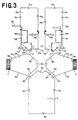
- Fig. 3 is an exploded plan view showing the outer garment 1 of Fig. 1 and Fig. 4 is an assembled view showing the outer garment 1 of which the front trunk region 4, the rear trunk halves 5A, 5B and the sleeves 3A, 3B are bonded together.
- the front trunk region 4 has the both side edges 4a, 4b longitudinally extending in parallel to each other, and upper and lower ends 4c, 4d transversely extending in parallel to each other.
- a neckline 4e is formed substantially in the middle of the upper end 4c of the front trunk region 4, and armholes 4f are formed on the both sides of the neckline 4e.
- the neckline 4e describes a circular arc so that it is convexly curved in the direction of the lower end 4d of the front trunk region 4.
- the armholes 4f extend downward from the both sides of the neckline 4e toward the both side edges 4a, 4b of the front trunk region 4 obliquely with respect to the lower end 4d.
- the first and second rear trunk halve 5B are identical to each other in shape as well as in size and each of them has a free side edge 5a and a fixed side edge 5b longitudinally extending in parallel to each other and upper and lower ends 5c, 5d transversely extending in parallel to each other.
- the upper end 5c of the first rear trunk half 5A is formed with a neckline 5e extending from the free side edge 5a toward the middle of the upper end 5c and with an armhole 5f extending from the neckline 5e toward the fixed side edge 5b.
- the neckline 5e describes a circular arc so that it is convexly curved toward a lower end 5d of the first rear trunk half 5A.
- the armhole 5f extends downward from the neckline 5e toward the fixed side edge 5b obliquely with respect to the lower end 5d.
- a hook member 12 as a component of a mechanical fastener is attached to an edge of the neckline 5e.
- the upper end 5c of the second rear trunk half 5B is formed with a neckline 5e extending from the free side edge 5a toward the middle of the upper end 5c and with an armhole 5f extending from the neckline 5e toward the fixed side edge 5b.
- the neckline 5e describes a circular arc so that it is convexly curved toward the lower end 5d of the first rear trunk half 5A.
- the armhole 5f extends downward from the neckline 5e toward the fixed side edge 5b obliquely with respect to the lower end 5d.
- a loop member 13 as a component of the mechanical fastener is attached to an edge of the neckline 5e.
- first and second rear trunk halves 5A, 5B are respectively formed in zones S1, S2 placed aside toward the front trunk region 4 with the openings 6A, 6B by cutting these zones S1, S2 out from the respective rear trunk halves 5A, 5B.
- the tying cords 8A, 8B for waist portion of the first rear trunk half 5A have their one ends attached to outer surface of the first rear trunk half 5A in the vicinity of the free side edge 5a and to inner surface of the first rear trunk half 5A in the vicinity of the fixed side edge 5b at a level corresponding to the waist line of the first rear trunk half 5A.
- the tying cords 9A, 9B for waist portion of the second rear trunk half 5B have their one ends attached to the outer surface of the second rear half 5B in the vicinity of the free side edge 5a and the fixed side edge 5B.
- the sleeves 3A, 3B have first sleeve bonding regions 3a which extend in parallel to the armholes 4f of the front trunk region 4 and second sleeve bonding regions 3b which extend in parallel to the armholes 5f of the first and second rear trunk halves 5A, 5B.
- the first sleeve bonding regions 3a rectilinearly and obliquely extends downward from respective centers of the shoulder covering areas 3c to the trunk facing areas 3d.
- the second sleeve bonding regions 3b also rectilinearly and obliquely extend downward from the respective centers of the shoulder covering areas 3c to the trunk facing areas 3d.
- the respective armholes 4f of the front trunk region 4 are put in coincidence with the respective first sleeve bonding regions 3a of the sleeves 3A, 3B while the respective armholes 5f of the first and second rear trunk halves 5A, 5B are put in coincidence with the respective second sleeve bonding regions 3b of the sleeves 3A, 3B. From this state, the sleeves 3A, 3B are bonded to the front region 4, on one hand, and to the first and second rear trunk halves 5A, 5B, on the other hand.
- the neckline 4e of the front trunk region 4 is spaced apart from the necklines 5e of the first and second rear trunk halves 5A, 5B by a desired dimension. Between the respective necklines 4e, 5e of the front trunk region 4 and the rear trunk halves 5A, 5B, the shoulder covering areas 3c of the sleeves 3A, 3B not bonded to the armholes 4f, 5f of the trunk regions 4, 5A, 5B extend.
- the front trunk region 4 and the first and second rear trunk halves 5A, 5B are folded along the centerline X extending on the both sleeves 3A, 3B so that inner surfaces of the region 4 and the halves 5A, 5B are placed upon each other.
- the substantially both side edges 4a, 4b of the front trunk region 4 may be bonded to the substantially respective fixed side edges 5b of the first and second rear trunk halves 5A, 5B and the respective trunk facing areas 3d of the sleeves 3A, 3B may be bonded together to obtain the outer garment 1 of Fig. 1.
- the outer garment 1 it is preferable in the outer garment 1 to bond the outer surfaces of the respective sleeve bonding regions 3a, 3b of the sleeves 3A, 3B to the outer surfaces of these trunk regions 4, 5A, 5B with the armholes 4f, 5f of these trunk regions 4, 5A, 5B being folded a little toward inner surfaces of these trunk regions 4, 5A, 5B. It is preferable also to bond the outer surfaces of these trunk regions 4, 5A, 5B one to another with the substantially both side edges 4a, 4b of the front trunk region 4 and the substantially fixed side edges 5b of the first and second rear trunk halves 5A, 5B being folded a little toward the inner surfaces these trunk regions 4, 5A, 5B.
- a wearer puts the both arms through the sleeves 3A, 3B of the outer garment 1, fastens the tying cord 8A for waist portion attached to the inner surface of the first rear trunk half 5A and the tying cord 9A for waist portion attached to the outer surface of the second rear trunk half 5B to each other, and places the second rear trunk half 5B on the outer surface of the first rear trunk half 5A.
- the wearer closes the rear area by fastening the tying cord 8B for waist portion attached to the outer surface of the first rear trunk half 5A and the tying cord 9B for waist portion attached to the outer surface of the second rear trunk half 5B to each other.
- the fastener members 12, 13 may be engaged with each other to close the neckline.
- Fig. 5 is a rear view of the outer garment 1 according to another embodiment of this invention as viewed from the side of the rear trunk region 5 and Fig. 6 is an exploded plan view of the outer garment of Fig. 5.
- Fig. 5 shows the outer garment 1 being worn with the tying cords 8A, 8B, 9A, 9B for waist portion having been tied together and the fastener members 12, 13 having been engaged with each other.
- the outer garment 1 comprises a basic trunk portion 2 and sleeves 3A and 3B bonded to an upper end of the basic trunk portion 2 at both side edges thereof.
- the basic trunk portion 2 comprises, in turn, the front trunk region 4 the front trunk region 4, the first rear trunk half 5A contiguous to one side edge 4a of the front trunk region 4 and a second rear trunk half 5B contiguous to the other side edge 4b of the front trunk region 4. So far as such arrangement is concerned, this embodiment is similar to the embodiment shown in Fig. 1.
- Each of the sleeves 3A, 3B defines a cylindrical form tapered from a sleeve bonding region 3a, 3b to a cuff 3e.
- a ribbed member 7 is attached to the cuff 3e of the sleeve 3A, 3B and elastically stretchable in the circumferential direction of the sleeve 3A, 3B.
- the outer garment 1 is formed between the sleeves 3A, 3B along the upper end of the basic trunk portion 2 with a neck opening 10 and along the lower end of the basic trunk portion 2 with a hem opening 11.
- the front trunk region 4 has the both side edges 4a, 4b longitudinally extending in parallel to each other, and upper and lower ends 4c, 4d transversely extending in parallel to each other.
- a neckline 4e is formed substantially in the middle of the upper end 4c of the front trunk region 4, and armholes 4f are formed on the both sides of the neckline 4e.
- the first and second rear trunk halves 5A, 5B are identical to each other in shape as well as in size and each of them has a free side edge 5a and a fixed side edge 5b longitudinally extending in parallel to each other, upper and lower ends 5c, 5d transversely extending in parallel to each other, and the tying cords 8A, 8B, 9A, 9B for waist portion serving to keep the rear area of the garment closed.
- the upper end 5c of the first rear trunk half 5A is formed with the neckline 5e extending from the free side edge 5a toward the middle of the upper end 5c and with the armhole 5f extending from the neckline 5e toward the fixed side edge 5b.
- the hook member 12 as the component of the mechanical fastener is attached to the edge of the neckline 5e.
- the upper end 5c of the second rear trunk half 5B is formed with a neckline 5e extending from the free side edge 5a toward the middle of the upper end 5c and with an armhole 5f extending from the neckline 5e toward the fixed side edge 5b.
- the loop member 13 as the component of the mechanical fastener is attached to an edge of the neckline 5e.
- the first and second rear trunk halves 5A, 5B are formed with a plurality of rhombic openings 6A, 6B.
- the upper parts of the first and second rear trunk halves 5A, 5B are respectively formed in zones S1, S2 placed aside toward the front trunk region 4 with the openings 6A, 6B by cutting these zones S1, S2 out from the respective rear trunk halves 5A, 5B.
- these openings 6A, 6B are spaced apart from one another longitudinally as well as transversely of the first and second rear trunk halves 5A, 5B, respectively.
- the shape of the opening 6A, 6B is not limited to the rhombic shape but can be selected from a group including circular, oval and rectangular shapes.
- the sleeves 3A, 3B have first sleeve bonding regions 3a which extend in parallel to the armholes 4f of the front trunk region 4 and second sleeve bonding regions 3b which extend in parallel to the armholes 5f of the first and second rear trunk halves 5A, 5B.
- a dimension L1 by which respective crossing points P of the necklines 5e and the armholes 5f of the first and second rear trunk halves 5A, 5B are spaced apart from the zones S1, S2, respectively, is preferably in a range of 15 ⁇ 50 cm, more preferably in a range of 20 ⁇ 40 cm.
- a dimension L2 by which the zones S1, S2 are spaced apart from the fixed side edges 5b of the first and second rear trunk halves 5A, 5B is preferably in a range of 5 ⁇ 20 cm, more preferably in a range of 5 ⁇ 15 cm.
- the openings 6A, 6B may be positioned in the vicinity of the wearer's bladebones as the outer garment 1 is worn to ensure that the heat inside the outer garment 1 at its upper part can be effectively emanated outward from the outer garment 1 through the openings 6A, 6B.
- a total opening area of the respective zones S1, S2 is preferably in a range of 5 ⁇ 200 cm 2 .
- the total opening area less than 5 cm 2 would make it difficult to emanate the heat inside the outer garment 1 outward effectively.
- the total opening area exceeding 200 cm 2 would facilitate the heat emitted from the illuminator for a surgical operation to be conducted through the openings 6A, 6B to the wearer and thereby raise the wearer's body heat.
- the individual openings 6A, 6B are deformable longitudinally as well as transversely of the outer garment 1. Accordingly, tension transmitted from the sleeves 3A, 3B to the upper parts of the first and second rear trunk halves 5A, 5B is dispersed in the openings 6A, 6B. In this way, it is not apprehended that a high garment pressure might be generated at the upper parts of those rear trunk halves 5A, 5B.
- a hydrophobic nonwoven fabric of thermoplastic fiber or a laminated sheet of a hydrophobic nonwoven fabric and a flexible/breathable but a liquid-impervious thermoplastic synthetic resin sheet can be used as stock material for the front and rear trunk regions 4, 5A, 5B and the sleeves 3A, 3B.
- a laminated sheet it is preferable to use a synthetic resin sheet having its both surfaces are sandwiched between two layers of hydrophobic nonwoven fabric wherein these hydrophobic nonwoven fabric and synthetic resin sheet are intermittently bonded to each other at bonding spots in the form of dots or stripes.
- a plastic sheet for example, of polyethylene, polypropylene, polyethylene terephthalate or polyester as a synthetic resin sheet.
- a nonwoven fabric made porous to improve moisture-permeability, a nonwoven fabric embossed to form irregularities and thereby to improve cushioning property, a nonwoven fabric provided having a stretchability, or combination thereof can be also used as a nonwoven fabric to be used for this invention.
- Such nonwoven fabric may be selected from a group including spunlace-, needlepunch-, meltblown-, thermalbond-, spunbond- and chemicalbond-types. It is also possible to use a composite nonwoven fabric in which both sheet surfaces of a meltblown nonwoven fabric sheet having high water-resistance are sandwiched between sheet surfaces of spunbond nonwoven fabric sheets having high strength and flexibility.
- Polyolefine-, polyester-, or polyamide-based fiber or conjugate fiber of thick-and-thin type or side-by-side type of polyethylene/polypropylene or polyester can be used as component fiber of a nonwoven fabric.
- Hot melt or heat-sealing technique may be used to bond the front and rear trunk regions 4, 5A, 5B together, to bond the front and rear trunk regions 4, 5A, 5B to the sleeves 3A, 3B and to attach the tying cords 8A, 8B, 9A, 9B and the ribbed members 7 to the outer garment.
- each size for example, S, M, L, LL can be provided in consideration of a shape of wearer's body.
- the outer garment 1 is sterilized by organic gasifiable chemicals, for example ethyleneoxide, electronic beam, or radiation, after it has been put into a sterilizing bag.
- the first and second rear trunk halves are formed at the upper parts thereof in the zones placed aside toward the front trunk region with the openings so that each of the zones may have the desired total opening area.
- the openings may be positioned in the vicinity of the wearer's bladebones as the outer garment is worn to ensure that the heat inside the outer garment at its upper part can be effectively emanated outward from the outer garment through the openings.
Landscapes
- Engineering & Computer Science (AREA)
- Health & Medical Sciences (AREA)
- General Health & Medical Sciences (AREA)
- Physical Education & Sports Medicine (AREA)
- Textile Engineering (AREA)
- Environmental & Geological Engineering (AREA)
- Professional, Industrial, Or Sporting Protective Garments (AREA)
- Details Of Garments (AREA)
Applications Claiming Priority (2)
| Application Number | Priority Date | Filing Date | Title |
|---|---|---|---|
| JP2000176650A JP2001355110A (ja) | 2000-06-13 | 2000-06-13 | 使い捨て手術用外衣 |
| JP2000176650 | 2000-06-13 |
Publications (1)
| Publication Number | Publication Date |
|---|---|
| EP1163858A2 true EP1163858A2 (en) | 2001-12-19 |
Family
ID=18678354
Family Applications (1)
| Application Number | Title | Priority Date | Filing Date |
|---|---|---|---|
| EP01305109A Withdrawn EP1163858A2 (en) | 2000-06-13 | 2001-06-12 | Disposable outer garment for surgical operation |
Country Status (8)
| Country | Link |
|---|---|
| EP (1) | EP1163858A2 (zh) |
| JP (1) | JP2001355110A (zh) |
| KR (1) | KR20010112641A (zh) |
| CN (1) | CN1328792A (zh) |
| AU (1) | AU4806201A (zh) |
| BR (1) | BR0104243A (zh) |
| CA (1) | CA2348347A1 (zh) |
| ID (1) | ID30464A (zh) |
Cited By (5)
| Publication number | Priority date | Publication date | Assignee | Title |
|---|---|---|---|---|
| WO2004041010A1 (en) * | 2002-11-01 | 2004-05-21 | Kimberly-Clark Worldwide, Inc. | Surgical gown with limited discrete sections of elastomeric materials |
| WO2005046373A1 (en) * | 2003-11-06 | 2005-05-26 | Kimberly-Clark Worldwide, Inc. | Protective garment with elastomeric elbow patches |
| US7013488B2 (en) | 2003-12-10 | 2006-03-21 | Kimberly-Clark Worldwide, Inc. | Surgical gown with a panel section of elastomeric barrier material |
| FR3020921A1 (fr) * | 2014-05-15 | 2015-11-20 | Univ Haute Alsace | Blouse medicale |
| CN112931997A (zh) * | 2021-03-20 | 2021-06-11 | 宏昌生物医疗科技(平湖)有限公司 | 无菌一次性手术衣 |
Families Citing this family (7)
| Publication number | Priority date | Publication date | Assignee | Title |
|---|---|---|---|---|
| SE525415C2 (sv) * | 2002-07-03 | 2005-02-15 | Moelnlycke Health Care Ab | Värmeavgivande patientdräkt |
| JP2005350820A (ja) * | 2004-06-11 | 2005-12-22 | Olympus Corp | 防護衣 |
| WO2005120263A1 (ja) * | 2004-06-11 | 2005-12-22 | Olympus Corporation | 防護衣 |
| EP1865799B1 (en) * | 2005-03-24 | 2010-06-09 | Stryker Corporation | Personal protection system |
| US20100031427A1 (en) * | 2008-08-06 | 2010-02-11 | Aaron Drake Smith | Garment With Interior Surface Indicator |
| CN206213350U (zh) * | 2016-11-17 | 2017-06-06 | 深圳市善行医疗科技有限公司 | 可调节的手术衣 |
| KR200489311Y1 (ko) * | 2018-07-23 | 2019-05-30 | 이준호 | 통기성 천과 비닐을 이용한 일회용 감염방지 가운 |
-
2000
- 2000-06-13 JP JP2000176650A patent/JP2001355110A/ja active Pending
-
2001
- 2001-05-23 CA CA002348347A patent/CA2348347A1/en not_active Abandoned
- 2001-05-28 AU AU48062/01A patent/AU4806201A/en not_active Abandoned
- 2001-06-06 BR BR0104243-2A patent/BR0104243A/pt not_active IP Right Cessation
- 2001-06-06 ID IDP00200100441D patent/ID30464A/id unknown
- 2001-06-12 EP EP01305109A patent/EP1163858A2/en not_active Withdrawn
- 2001-06-13 CN CN01121185A patent/CN1328792A/zh active Pending
- 2001-06-13 KR KR1020010033076A patent/KR20010112641A/ko not_active Application Discontinuation
Cited By (6)
| Publication number | Priority date | Publication date | Assignee | Title |
|---|---|---|---|---|
| US6799331B2 (en) | 2001-11-19 | 2004-10-05 | Kimberly-Clark Worldwide, Inc. | Surgical gown with limited discrete sections of elastomeric materials |
| WO2004041010A1 (en) * | 2002-11-01 | 2004-05-21 | Kimberly-Clark Worldwide, Inc. | Surgical gown with limited discrete sections of elastomeric materials |
| WO2005046373A1 (en) * | 2003-11-06 | 2005-05-26 | Kimberly-Clark Worldwide, Inc. | Protective garment with elastomeric elbow patches |
| US7013488B2 (en) | 2003-12-10 | 2006-03-21 | Kimberly-Clark Worldwide, Inc. | Surgical gown with a panel section of elastomeric barrier material |
| FR3020921A1 (fr) * | 2014-05-15 | 2015-11-20 | Univ Haute Alsace | Blouse medicale |
| CN112931997A (zh) * | 2021-03-20 | 2021-06-11 | 宏昌生物医疗科技(平湖)有限公司 | 无菌一次性手术衣 |
Also Published As
| Publication number | Publication date |
|---|---|
| CA2348347A1 (en) | 2001-12-13 |
| ID30464A (id) | 2001-12-13 |
| CN1328792A (zh) | 2002-01-02 |
| JP2001355110A (ja) | 2001-12-26 |
| AU4806201A (en) | 2001-12-20 |
| KR20010112641A (ko) | 2001-12-20 |
| BR0104243A (pt) | 2002-01-22 |
Similar Documents
| Publication | Publication Date | Title |
|---|---|---|
| US6378136B2 (en) | Disposable gown | |
| EP1147718A2 (en) | Disposable gown | |
| US6564386B2 (en) | Disposable surgical gown of back-closable type | |
| ES2273968T3 (es) | Bata quirurgica desechable. | |
| AU779421B2 (en) | Disposable pants of trunks-type | |
| EP1163858A2 (en) | Disposable outer garment for surgical operation | |
| JP2004525274A (ja) | 防護服 | |
| US9357806B2 (en) | Medical examination gown | |
| EP1157619A2 (en) | Disposable gown | |
| JP3764038B2 (ja) | 背部閉じ合せ型の使い捨て外衣 | |
| JP2002235223A (ja) | 背側閉じ合わせ型の使い捨て外衣 | |
| WO2001003527A1 (fr) | Vetement jetable | |
| JP2002220715A (ja) | 使い捨ての手術用外衣 | |
| JP6118085B2 (ja) | 使い捨てパンツ型おむつ | |
| WO2001003524A1 (fr) | Article vestimentaire jetable | |
| JP2021008693A (ja) | インナーウェア | |
| JP2014104290A (ja) | 使い捨てパンツ型おむつ | |
| JP2014104292A (ja) | 使い捨てパンツ型おむつ |
Legal Events
| Date | Code | Title | Description |
|---|---|---|---|
| PUAI | Public reference made under article 153(3) epc to a published international application that has entered the european phase |
Free format text: ORIGINAL CODE: 0009012 |
|
| STAA | Information on the status of an ep patent application or granted ep patent |
Free format text: STATUS: THE APPLICATION HAS BEEN WITHDRAWN |
|
| AK | Designated contracting states |
Kind code of ref document: A2 Designated state(s): AT BE CH CY DE DK ES FI FR GB GR IE IT LI LU MC NL PT SE TR |
|
| AX | Request for extension of the european patent |
Free format text: AL;LT;LV;MK;RO;SI |
|
| 18W | Application withdrawn |
Withdrawal date: 20011112 |