EP1161915B1 - Luftströmungskanal - Google Patents
LuftströmungskanalInfo
- Publication number
- EP1161915B1 EP1161915B1 EP01107221A EP01107221A EP1161915B1 EP 1161915 B1 EP1161915 B1 EP 1161915B1 EP 01107221 A EP01107221 A EP 01107221A EP 01107221 A EP01107221 A EP 01107221A EP 1161915 B1 EP1161915 B1 EP 1161915B1
- Authority
- EP
- European Patent Office
- Prior art keywords
- structuring
- flow channel
- air flow
- suction
- wall
- Prior art date
- Legal status (The legal status is an assumption and is not a legal conclusion. Google has not performed a legal analysis and makes no representation as to the accuracy of the status listed.)
- Expired - Lifetime
Links
- 238000007664 blowing Methods 0.000 claims abstract description 5
- 230000001965 increasing effect Effects 0.000 description 11
- 238000004049 embossing Methods 0.000 description 3
- XLYOFNOQVPJJNP-UHFFFAOYSA-N water Substances O XLYOFNOQVPJJNP-UHFFFAOYSA-N 0.000 description 3
- 238000005299 abrasion Methods 0.000 description 2
- 238000005422 blasting Methods 0.000 description 2
- 230000008021 deposition Effects 0.000 description 2
- 238000005530 etching Methods 0.000 description 2
- 238000010030 laminating Methods 0.000 description 2
- 238000004519 manufacturing process Methods 0.000 description 2
- 239000002985 plastic film Substances 0.000 description 2
- 229920006255 plastic film Polymers 0.000 description 2
- 241000251468 Actinopterygii Species 0.000 description 1
- 241001295925 Gegenes Species 0.000 description 1
- 230000000694 effects Effects 0.000 description 1
- 230000007613 environmental effect Effects 0.000 description 1
- 230000003628 erosive effect Effects 0.000 description 1
- 230000001747 exhibiting effect Effects 0.000 description 1
- 239000004744 fabric Substances 0.000 description 1
- 230000002349 favourable effect Effects 0.000 description 1
- 230000001939 inductive effect Effects 0.000 description 1
- 238000001746 injection moulding Methods 0.000 description 1
- 239000000463 material Substances 0.000 description 1
- 238000000034 method Methods 0.000 description 1
- 238000004904 shortening Methods 0.000 description 1
- 238000005245 sintering Methods 0.000 description 1
- 239000004753 textile Substances 0.000 description 1
Images

Classifications
-
- F—MECHANICAL ENGINEERING; LIGHTING; HEATING; WEAPONS; BLASTING
- F15—FLUID-PRESSURE ACTUATORS; HYDRAULICS OR PNEUMATICS IN GENERAL
- F15D—FLUID DYNAMICS, i.e. METHODS OR MEANS FOR INFLUENCING THE FLOW OF GASES OR LIQUIDS
- F15D1/00—Influencing flow of fluids
- F15D1/02—Influencing flow of fluids in pipes or conduits
- F15D1/06—Influencing flow of fluids in pipes or conduits by influencing the boundary layer
- F15D1/065—Whereby an element is dispersed in a pipe over the whole length or whereby several elements are regularly distributed in a pipe
-
- A—HUMAN NECESSITIES
- A47—FURNITURE; DOMESTIC ARTICLES OR APPLIANCES; COFFEE MILLS; SPICE MILLS; SUCTION CLEANERS IN GENERAL
- A47L—DOMESTIC WASHING OR CLEANING; SUCTION CLEANERS IN GENERAL
- A47L9/00—Details or accessories of suction cleaners, e.g. mechanical means for controlling the suction or for effecting pulsating action; Storing devices specially adapted to suction cleaners or parts thereof; Carrying-vehicles specially adapted for suction cleaners
- A47L9/0072—Mechanical means for controlling the suction or for effecting pulsating action
-
- A—HUMAN NECESSITIES
- A47—FURNITURE; DOMESTIC ARTICLES OR APPLIANCES; COFFEE MILLS; SPICE MILLS; SUCTION CLEANERS IN GENERAL
- A47L—DOMESTIC WASHING OR CLEANING; SUCTION CLEANERS IN GENERAL
- A47L9/00—Details or accessories of suction cleaners, e.g. mechanical means for controlling the suction or for effecting pulsating action; Storing devices specially adapted to suction cleaners or parts thereof; Carrying-vehicles specially adapted for suction cleaners
- A47L9/0081—Means for exhaust-air diffusion; Means for sound or vibration damping
-
- A—HUMAN NECESSITIES
- A47—FURNITURE; DOMESTIC ARTICLES OR APPLIANCES; COFFEE MILLS; SPICE MILLS; SUCTION CLEANERS IN GENERAL
- A47L—DOMESTIC WASHING OR CLEANING; SUCTION CLEANERS IN GENERAL
- A47L9/00—Details or accessories of suction cleaners, e.g. mechanical means for controlling the suction or for effecting pulsating action; Storing devices specially adapted to suction cleaners or parts thereof; Carrying-vehicles specially adapted for suction cleaners
- A47L9/02—Nozzles
-
- A—HUMAN NECESSITIES
- A47—FURNITURE; DOMESTIC ARTICLES OR APPLIANCES; COFFEE MILLS; SPICE MILLS; SUCTION CLEANERS IN GENERAL
- A47L—DOMESTIC WASHING OR CLEANING; SUCTION CLEANERS IN GENERAL
- A47L9/00—Details or accessories of suction cleaners, e.g. mechanical means for controlling the suction or for effecting pulsating action; Storing devices specially adapted to suction cleaners or parts thereof; Carrying-vehicles specially adapted for suction cleaners
- A47L9/24—Hoses or pipes; Hose or pipe couplings
Definitions
- the invention relates to an air flow channel of a Marshssauguzes or -blasuzes, in particular a vacuum cleaner, according to the features of the preamble of claim 1.
- suction and blowing ducts are to be adapted to the design of internal and external functional elements, such as bottlenecks, curves, normalized interfaces, etc., and on the other hand to be made favorable production, smooth, easily demoldable surfaces are preferred.
- such surfaces in combination with secondary requirements lead to the disadvantage that a sequence of zones of different flow velocities leads to power losses.
- a deposition of media in dead water areas or demoulding offset-ridge zones is observed.
- this results in an increased noise emission.
- disadvantages result from erosion and / or cavities in the impact areas.
- the invention has the object to form an air flow channel of the assumed type advantageous.
- This object is achieved initially and essentially by the subject matter of claim 1 by a leading to a microfluidizing structuring of the inner wall of the air flow channel.
- an increased efficiency of the Swssaugilless is achieved.
- the noise emission is reduced and the effects of production-related inaccuracies are reduced.
- Deposits and abrasion are reduced.
- the structuring according to the invention of the inner wall of the air flow channel an equally high air output at the suction or blowing nozzle can be achieved with reduced recording power of up to 20%.
- the inner wall of the air flow channel has a structuring which favors the microfluidization and suppresses macro-swirling or dead water areas.
- the structuring can be natural leaning or freely constructed and produced directly by means of photographing, etching, blasting, embossing, laminating, lacquering or by means of rapid prototyping, so that the structuring can be reproduced as desired. You can here on tools for forming processes, such. As injection molding, embossing or sintering.
- the invention also provides that a conventional, standard air flow channel with a, a microfluidization inducing plastic film is pasted.
- the structuring can represent approximately the surface of the skin of large fish, wherein further this structuring can be provided partially or even over the entire surface.
- the structuring is groove-like.
- a disorderly structured structuring is conceivable.
- the structuring be formed on most of the inner wall of the air treatment channel from a suction air inlet to the Saug Kunststoffgebläseeinlass. Accordingly, it is also proposed that the structuring be formed on most of the inner wall of the air flow channel from a Blas Kunststoffgebläseauslass to a Blas Kunststoffauslass. Also, the invention provides that the structuring is formed in hundredths to tenths of a millimeter range.
- the structuring according to the invention leads to an increase in the efficiency and thus the air power, to reduce the noise emission and to reduce deposition and wear by transported media, this without increasing the engine power. The sum of the benefits accumulates to increased environmental compatibility of the device.
- the formed in the suction nozzle 3 suction air inlet is provided with the reference numeral 3 '.
- an air flow channel 4 -in the case of the suction nozzle 3 on the vacuum cleaner 1- extends essentially as far as a suction air inlet 2 'of the suction / blower motor 2.
- Both the vacuum cleaner 1 and the suction nozzle 3 each have an air flow channel 4, through which the sucked medium, a docked to the motor housing 5, not shown filter is passed through.
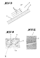
- a portion of an air flow channel 4 is shown in a schematic sectional view.
- the inner wall 6 of the air flow channel 4 is provided with a structuring 7 which, in the suction or blowing operation, leads to a microfluidization of the medium passed by.
- This structuring can be generated directly by means of photographing, etching, blasting, embossing, laminating or lacquering or by means of rapid prototyping.
- a plastic film provided with a structuring may also be applied to the inner wall 6 of the air flow channel.
- an air cushion is created by the microfluidization in the region of the inner wall surface, which supports an undisturbed flow of the medium 8 in the air flow channel 4 (see Fig. 3).
- the structuring 7 is of scale-like design with an orientation pointing in the direction of flow r the individual scales. These scales also have a substructuring 7 'according to FIG. 5. As can be seen, this substructuring 7 'can be formed by circular segment-shaped, optionally intermeshing grooves.
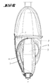
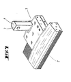
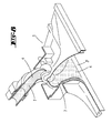
- FIGS. 6 to 8 show various device sections or additional device parts with flow channels 4 according to the invention, having a structuring 7.
Landscapes
- Engineering & Computer Science (AREA)
- Mechanical Engineering (AREA)
- Physics & Mathematics (AREA)
- Fluid Mechanics (AREA)
- General Engineering & Computer Science (AREA)
- Structures Of Non-Positive Displacement Pumps (AREA)
- Jet Pumps And Other Pumps (AREA)
- Nozzles For Electric Vacuum Cleaners (AREA)
- Filtering Of Dispersed Particles In Gases (AREA)
- Exhaust Gas After Treatment (AREA)
- Infusion, Injection, And Reservoir Apparatuses (AREA)
- Fluid-Pressure Circuits (AREA)
Description
- Die Erfindung betrifft einen Luftströmungskanal eines Haushaltssauggerätes oder ―blasgerätes, insbesondere eines Staubsauggerätes, nach den Merkmalen des Oberbegriffes des Anspruches 1.
- Zur Erzielung möglichst hoher Luftleistung bspw. an einer Staubsaugerdüse ist es ohne Erhöhung der Aufnahmeleistung des Motors üblich, Strömungswege hinsichtlich Durchmesser, Glätte, Umlenkung, Querschnitte und Querschnittsänderungen zu optimieren. Die mediumberührte Seite (Innenseite) von Saug- und Blaskanälen wird allgemein auf maximal erreichbare Glätte und Minimierung von Versatz, Totwassergebieten und Verwirbelungen eingestellt. Eine Luftleitungssteigerung durch Erhöhung der Aufnahmeleistung des Blas- bzw. Saugmotors führt zu einer erhöhten Geräuschemission. Zudem stellt sich ein schlechterer Wirkungsgrad ein, was zu einer Verkürzung der Lebensdauer des Motors führt. Zudem ergibt sich hieraus eine erhöhte Abrasion in dem Luftströmungskanal. Da Saug- und Blaskanäle an die Gestaltung innerer und äußerer Funktionselemente, wie Engstellen, Kurven, normierte Schnittstellen usw. anzupassen sind und andererseits herstellungsgünstig ausgebildet sein sollen, werden glatte, leicht entformbare Oberflächen bevorzugt. Derartige Oberflächen in Kombination mit sekundären Erfordernissen führen zum einen zu dem Nachteil, dass eine Abfolge von Zonen verschiedener Strömungsgeschwindigkeiten zu Leistungsverlusten führt. Zudem wird eine Ablagerung von Medien in Totwassergebieten bzw. entformungsbedingten Versatz-Grat-Zonen beobachtet. Darüber hinaus ergibt hier eine erhöhte Schallemission. Weiter ergeben sich Nachteile durch Erosion und/oder Kavitäten in den Prallgebieten.
- Aus dem nächstliegenden Stand der Technik US-A-5 953 787 ist ein Luftströmungskanal eines Haushaltsgerätes bekannt, der auf seiner Innenfläche mit Haaren einer bestimmten Länge besetzt ist. Im Weiteren ist es bekannt, vgl. DE 26 15 507 A1, den Strömungskanal eines Haushaltsgerätes auf der Innenseite mit einem gerauhten Gewebe oder einem sonstigen gerauhten Textilen-Material auszukleiden. Darüber hinaus auch, eine Beflockung vorzusehen.
- Ausgehend von dem zunächst genannten Stand der Technik stellt sich der Erfindung die Aufgabe, einen Luftströmungskanal der vorausgesetzten Art vorteilhaft auszubilden.
- Diese Aufgabe ist beim Gegenstand des Anspruches 1 gelöst, wobei darauf abgestellt ist, dass die Strukturierung im Hunderstel- bis Zehntel-Millimeter-Bereich ausgebildet ist und dass die Strukturierung schuppenartig ausgebildet ist. Hierdurch ist ein erhöhter Wirkungsgrad des 1 laushaltssauggerätes erzielt.
- Im Hinblick auf den zuvor beschriebenen Stand der Technik wird eine technische Problematik der Erfindung darin gesehen, einen Luftströmungskanal der in Rede stehenden Art derart in vorteilhafter Weise weiterzubilden, dass sich eine Erhöhung des Wirkungsgrades des Haushaltssauggerätes oder -blasgerätes einstellt.
- Diese Aufgabe ist zunächst und im wesentlichen durch den Gegenstand des Anspruches 1 durch eine zu einer Mikroverwirbelung führende Strukturierung der Innenwandung des Luftströmungskanales gelöst. Zufolge dieser Ausgestaltung ist ein erhöhter Wirkungsgrad des Haushaltssauggerätes erzielt. Desweiteren wird die Schallemission verringert sowie die Einflüsse von fertigungsbedingten Ungenauigkeiten reduziert. Ablagerungen sowie Abrasion werden verringert. Als Folge der erfindungsgemäßen Strukturierung der Innenwandung des Luftströmungskanales läßt sich eine gleich hohe Luftleistung an der Saug- oder Blasdüse bei verringerter Aufnahmeleistung von bis zu 20 % erzielen. Die Innenwandung des Luftströmungskanales weist erfindungsgemäß eine Strukturierung auf, die die Mikroverwirbelung begünstigt und Makroverwirbelungen bzw. Totwassergebiete unterdrückt. Die Strukturierung kann naturentlehnt oder frei konstruiert sein und mittels Fotografierens, Ätzens, Strahlens, Prägens, Kaschierens, Lackierens oder mittels Rapid-Prototyping direkt erzeugt werden, so dass die Strukturierung beliebig vervielfältigbar ist. Sie kann hierbei auf Werkzeuge für formgebende Verfahren, wie z. B. Spritzgießen, Prägen oder Sintern übertragen werden. Darüber hinaus ist erfindungsgemäß auch vorgesehen, dass ein üblicher, serienmäßiger Luftströmungskanal mit einer, eine Mikroverwirbelung herbeiführende Kunststoffolie beklebt ist. So kann die Strukturierung annähernd die Oberfläche der Haut von Grossfischen darstellen, wobei weiter diese Strukturierung partiell oder auch vollflächig vorgesehen sein kann. Weiter ist auch denkbar, dass die Strukturierung rillenartig ausgebildet ist. Zudem ist auch eine ungeordnet ausgebildete Strukturierung denkbar. Weiter wird vorgeschlagen, dass die Strukturierung auf dem größten Teil der Innenwandung des Luftsträmungskanales von einem Sauglufteinlass bis zum Saugluftgebläseeinlass ausgebildet ist. Entsprechend wird auch vorgeschlagen, dass die Strukturierung auf dem größten Teil der Innenwandung des Luftströmungskanales von einem Blasluftgebläseauslass bis zu einem Blasluftauslass ausgebildet ist. Auch ist erfindungsgemäß vorgesehen, dass die Strukturierung im Hundertstel- bis Zehntel-Millimeter-Bereich ausgebildet ist. Die erfindungsgemäße Strukturierung führt zu einer Anhebung des Wirkungsgrades und damit der Luftleistung, zur Verringerung der Schallemission sowie zur Verringerung von Ablagerung und Verschleiß durch transportierte Medien, dies ohne Anhebung der Motorleistung. Die Summe der Vorteile kumuliert zu erhöhter Umweltverträglichkeit des Gerätes.
- Nachstehend ist die Erfindung anhand der beigefügten Zeichnung, welche lediglich Ausführungsbeispiele darfstellt, näher erläutert. Es zeigt:
- Fig. 1
- ein Ilaushaltssauggerät in Form eines Staubsauggeräts in perspektivischer Darstellung;
- Fig. 2
- eine schematische Teildarstellung eines, die erfindungsgemäße, innenwandungsseitige Strukturierung aufweisenden Luftströmungskanals;
- Fig. 3
- eine schematische Schnittdarstellung gemäß der Linie III-III in Fig. 2;
- Fig. 4
- eine Herausvergrößerung des Bereiches IV in Fig. 2;
- Fig. 5
- eine mikroskopische Vergrößerung des Bereiches V in Fig. 4;
- Fig. 6
- eine Ansicht gegen das, einen erfindungsgemäßen Luftströmungskanal aufweisenden Motor-/Filter-Gehäuse des Staubsauggerätes gemäß Fig. 1;
- Fig. 7
- eine perspektivische Darstellung einer Saugdüse des Staubsauggerätes;
- Fig. 8
- eine partiell geschnittene, perspektivische Prinzipdarstellung einer Saugdüse mit einem, die erfindungsgemäße Strukturierung aufweisendem Luftströmungskanal.
- Dargestellt und beschrieben ist zunächst mit Bezug zu Fig. 1 ein Haushaltsgerät in Form eines Staubsauggerätes 1, mit einem Saug-/Gebläsemotor 2 und einer zugeordneten Saugdüse 3.
- Der in der Saugdüse 3 ausgebildete Sauglufteinlaß ist mit dem Bezugszeichen 3' versehen. Von diesem ausgehend erstreckt sich ein Luftströmungskanal 4 -bei Anordnung der Saugdüse 3 an dem Staubsauggerät 1- im wesentlichen bis hin zu einem Sauglufteinlaß 2' des Saug-/Gebläsemotors 2.
- Sowohl das Staubsauggerät 1 als auch die Saugdüse 3 verfügen jeweils über einen Luftströmungskanal 4, durch welchen das angesaugte Medium, einen an dem Motorgehäuse 5 angedockten, nicht dargestellten Filter durchströmend geleitet wird.
- In Fig. 2 ist ein Abschnitt eines Luftströmungskanales 4 in einer schematischen Schnittdarstellung gezeigt. Erfindungsgemäß ist die Innenwandung 6 des Luftströmungskanales 4 mit einer Strukturierung 7 versehen, welche im Saug- oder auch Blasbetrieb zu einer Mikroverwirbelung des vorbeigeführten Mediums führt. Diese Strukturierung kann mittels Fotografierens, Ätzens, Strahlens, Prägens, Kaschierens oder Lackierens oder mittels Rapid-Prototyping direkt erzeugt sein. Alternativ kann auch eine mit einer Strukturierung versehene Kunststofffolie auf der Innenwandung 6 des Luftströmungskanales aufgebracht sein.
- Durch die so geschaffene Oberfläche der Innenwandung 6 des Luftströmungskanales 4 wird eine Mikroverwirbelung begünstigt, jedoch eine Makroverwirbelung bzw. Totwassergebiete unterdrückt, so daß bei gleicher Aufnahmeleistung des Saug-/Gebläsemotors 2 eine erhöhte Luftleistung bzw. bei gleich hoher Luftleistung eine verringerte Aufnahmeleistung erzielt ist. Zufolge der erfindungsgemäßen Ausgestaltung wird durch die Mikroverwirbelung im Bereich der Innenwandungsoberfläche ein Luftpolster geschaffen, welches ein ungestörtes Strömen des Mediums 8 in dem Luftströmungskanal 4 unterstützt (vergl. Fig. 3).
- Wie in Fig. 4 dargestellt, ist in dem Ausführungsbeispiel die Strukturierung 7 schuppenartig ausgebildet mit einer in Strömungsrichtung r weisenden Ausrichtung der einzelnen Schuppen. Diese Schuppen weisen weiter eine Unterstrukturierung 7' gemäß Fig. 5 auf. Wie zu erkennen, kann diese Unterstrukturierung 7' durch kreisabschnittförmige, gegebenenfalls ineinandergreifende Rillen gebildet sein.
- Die Fig. 6 bis 8 zeigen verschiedene Geräteabschnitte bzw. Gerätezusatzteile mit erfindungsgemäßen, eine Strukturierung 7 aufweisenden Strömungskanälen 4.
Claims (6)
- Luftströmungskanal (4) eines Haushaltssauggerätes oder -blasgerätes, insbesondere eines Staubsauggerätes, mit einer zu einer Mikroverwirbelung führenden Strukturierung der Innenwandung des Luftströmungskanales (4), dadurch gekennzeichnet, dass die Strukturierung im Hunderstel- bis Zehntel-Millimeter-Bereich ausgebildet ist und dass die Strukturierung schuppenartig ausgebildet ist.
- Luftströmungskanal nach Anspruch 1, dadurch gekennzeichnete dass eine Unterstrukturierung vorgesehen ist.
- Luftströmungskanal nach Anspruch 2, dadurch gekennzeichnet, dass die Unterstrukturierung rillenartig ist.
- Luftströmungskanal nach einem der Ansprüche 1 bis 3, dadurch gekennzeichnet, dass die Strukturierung schuppenartig ausgebildet ist..
- Luftströmungskanal nach einem der Ansprüche 1 bis 4, dadurch gekennzeichnet, dass die Strukturierung rillenartig ausgebildet ist.
- Luftströmungskanal nach einem der Ansprüche 1 bis 4, dadurch gekennzeichnet, dass die Strukturierung ungeordnet ausgebildet ist.
Priority Applications (1)
| Application Number | Priority Date | Filing Date | Title |
|---|---|---|---|
| SI200130666T SI1161915T1 (sl) | 2000-04-18 | 2001-03-23 | Kanal zracnega toka |
Applications Claiming Priority (4)
| Application Number | Priority Date | Filing Date | Title |
|---|---|---|---|
| DE10019125 | 2000-04-18 | ||
| DE10019125 | 2000-04-18 | ||
| DE10023408A DE10023408A1 (de) | 2000-04-18 | 2000-05-12 | Luftströmungskanal |
| DE10023408 | 2000-05-12 |
Publications (3)
| Publication Number | Publication Date |
|---|---|
| EP1161915A2 EP1161915A2 (de) | 2001-12-12 |
| EP1161915A3 EP1161915A3 (de) | 2005-04-20 |
| EP1161915B1 true EP1161915B1 (de) | 2006-10-04 |
Family
ID=26005361
Family Applications (1)
| Application Number | Title | Priority Date | Filing Date |
|---|---|---|---|
| EP01107221A Expired - Lifetime EP1161915B1 (de) | 2000-04-18 | 2001-03-23 | Luftströmungskanal |
Country Status (4)
| Country | Link |
|---|---|
| EP (1) | EP1161915B1 (de) |
| AT (1) | ATE341268T1 (de) |
| DE (1) | DE50111125D1 (de) |
| ES (1) | ES2270913T3 (de) |
Cited By (2)
| Publication number | Priority date | Publication date | Assignee | Title |
|---|---|---|---|---|
| US7845046B2 (en) | 2003-10-15 | 2010-12-07 | Black & Decker, Inc. | Hand-held cordless vacuum cleaner |
| US8032984B2 (en) | 2006-01-27 | 2011-10-11 | Black & Decker Inc. | Vacuum cleaner filter cleaning mechanisms |
Families Citing this family (1)
| Publication number | Priority date | Publication date | Assignee | Title |
|---|---|---|---|---|
| CN106949099B (zh) * | 2017-04-28 | 2019-05-10 | 苏州市海朋电子商务有限公司 | 吸尘器用电机风泵 |
Family Cites Families (6)
| Publication number | Priority date | Publication date | Assignee | Title |
|---|---|---|---|---|
| FR685301A (fr) * | 1929-11-23 | 1930-07-09 | Tuyau à surface intérieure à gradins | |
| DE2615507A1 (de) * | 1976-04-09 | 1977-10-20 | Mauz & Pfeiffer Progress | Staubsauger, insbesondere elektrisch betriebener haushaltstaubsauger |
| JP3047984B2 (ja) * | 1990-04-18 | 2000-06-05 | 株式会社日立製作所 | 電気掃除機 |
| US5067584A (en) * | 1990-04-25 | 1991-11-26 | Williams William H | Low cost replaceable type sound dampening unit for vacuum cleaning machine |
| KR0136305Y1 (ko) * | 1996-09-10 | 1999-02-01 | 최진호 | 진공청소기의 흡입구체 |
| DE19836873A1 (de) * | 1998-06-24 | 1999-12-30 | Montaplast Gmbh | Fluidführungselement für Wärmekraftmaschinen mit strömungstechnisch optimierter Oberflächenstruktur |
-
2001
- 2001-03-23 DE DE50111125T patent/DE50111125D1/de not_active Expired - Fee Related
- 2001-03-23 EP EP01107221A patent/EP1161915B1/de not_active Expired - Lifetime
- 2001-03-23 AT AT01107221T patent/ATE341268T1/de not_active IP Right Cessation
- 2001-03-23 ES ES01107221T patent/ES2270913T3/es not_active Expired - Lifetime
Cited By (3)
| Publication number | Priority date | Publication date | Assignee | Title |
|---|---|---|---|---|
| US7845046B2 (en) | 2003-10-15 | 2010-12-07 | Black & Decker, Inc. | Hand-held cordless vacuum cleaner |
| US8549704B2 (en) | 2003-10-15 | 2013-10-08 | Black & Decker Inc. | Hand-held cordless vacuum cleaner |
| US8032984B2 (en) | 2006-01-27 | 2011-10-11 | Black & Decker Inc. | Vacuum cleaner filter cleaning mechanisms |
Also Published As
| Publication number | Publication date |
|---|---|
| DE50111125D1 (de) | 2006-11-16 |
| EP1161915A2 (de) | 2001-12-12 |
| ES2270913T3 (es) | 2007-04-16 |
| ATE341268T1 (de) | 2006-10-15 |
| EP1161915A3 (de) | 2005-04-20 |
Similar Documents
| Publication | Publication Date | Title |
|---|---|---|
| EP3775571B1 (de) | Ventilator und einströmgitter für einen ventilator | |
| EP3228297B1 (de) | Druckwellenmassagegerät | |
| WO2018007120A1 (de) | Blutpumpe zur herzunterstützung | |
| DE10112010B4 (de) | Luftführungskanal und Kraftfahrzeugs-Heiz-, Belüftungs- und oder Klimaanlage | |
| WO2000045044A1 (de) | Ansaugvorrichtung mit einem durchbrüche aufweisenden leitungsabschnitt | |
| EP1886731B1 (de) | Sprühdüsenanordnung | |
| DE3128625C2 (de) | Seitenkanalgebläse | |
| EP2282135B1 (de) | Ventilator | |
| EP4700248A1 (de) | Laufrad für diagonal- oder radialventilatoren, spritzgusswerkzeug zur herstellung eines solchen laufrades sowie gerät mit wenigstens einem solchen laufrad | |
| DE60113819T2 (de) | Saugrohr mit abrupter querschnittserweiterung für eine brennkraftmaschine | |
| DE3238972A1 (de) | Horizontal geteiltes gehaeuse einer stroemungsmaschine | |
| DE2331614A1 (de) | Seitenkanal-geblaese | |
| EP1574771A3 (de) | Ventil für den Einsatz in Streckblasmaschinen | |
| EP0519967A1 (de) | Austragkopf für medien. | |
| DE3822267A1 (de) | Ringkanalgeblaese | |
| EP1165965B1 (de) | Seitenkanalverdichter | |
| EP0654124A1 (de) | Ejektorpumpe | |
| DE3528963A1 (de) | Oelfoerdervorrichtung fuer einen rotationsverdichter | |
| EP3114354A1 (de) | Lüfterrad eines axiallüfters | |
| EP4170177B1 (de) | Doppelpumpe | |
| DE10023408A1 (de) | Luftströmungskanal | |
| EP1161915A2 (de) | Luftströmungskanal | |
| DE19736678A1 (de) | Mehrstufige Seitenkanalpumpe | |
| DE19932826A1 (de) | Rohr mit veränderbarem Ansaugquerschnitt | |
| DE102016009028A1 (de) | Rotor-Stator-System mit einem Einlauftrichter für eine Exzenterschneckenpumpe |
Legal Events
| Date | Code | Title | Description |
|---|---|---|---|
| PUAI | Public reference made under article 153(3) epc to a published international application that has entered the european phase |
Free format text: ORIGINAL CODE: 0009012 |
|
| AK | Designated contracting states |
Kind code of ref document: A2 Designated state(s): AT BE CH CY DE DK ES FI FR GB GR IE IT LI LU MC NL PT SE TR |
|
| AX | Request for extension of the european patent |
Free format text: AL;LT;LV;MK;RO;SI |
|
| PUAL | Search report despatched |
Free format text: ORIGINAL CODE: 0009013 |
|
| AK | Designated contracting states |
Kind code of ref document: A3 Designated state(s): AT BE CH CY DE DK ES FI FR GB GR IE IT LI LU MC NL PT SE TR |
|
| AX | Request for extension of the european patent |
Extension state: AL LT LV MK RO SI |
|
| RIC1 | Information provided on ipc code assigned before grant |
Ipc: 7A 47L 5/28 B Ipc: 7F 15D 1/06 B Ipc: 7F 15D 1/02 B Ipc: 7A 47L 9/24 B Ipc: 7A 47L 9/00 A |
|
| 17P | Request for examination filed |
Effective date: 20050930 |
|
| AKX | Designation fees paid |
Designated state(s): AT BE CH CY DE DK ES FI FR GB GR IE IT LI LU MC NL PT SE TR |
|
| AXX | Extension fees paid |
Extension state: SI Payment date: 20050930 |
|
| GRAP | Despatch of communication of intention to grant a patent |
Free format text: ORIGINAL CODE: EPIDOSNIGR1 |
|
| GRAS | Grant fee paid |
Free format text: ORIGINAL CODE: EPIDOSNIGR3 |
|
| GRAA | (expected) grant |
Free format text: ORIGINAL CODE: 0009210 |
|
| AK | Designated contracting states |
Kind code of ref document: B1 Designated state(s): AT BE CH CY DE DK ES FI FR GB GR IE IT LI LU MC NL PT SE TR |
|
| AX | Request for extension of the european patent |
Extension state: SI |
|
| PG25 | Lapsed in a contracting state [announced via postgrant information from national office to epo] |
Ref country code: IT Free format text: LAPSE BECAUSE OF FAILURE TO SUBMIT A TRANSLATION OF THE DESCRIPTION OR TO PAY THE FEE WITHIN THE PRESCRIBED TIME-LIMIT;WARNING: LAPSES OF ITALIAN PATENTS WITH EFFECTIVE DATE BEFORE 2007 MAY HAVE OCCURRED AT ANY TIME BEFORE 2007. THE CORRECT EFFECTIVE DATE MAY BE DIFFERENT FROM THE ONE RECORDED. Effective date: 20061004 Ref country code: IE Free format text: LAPSE BECAUSE OF FAILURE TO SUBMIT A TRANSLATION OF THE DESCRIPTION OR TO PAY THE FEE WITHIN THE PRESCRIBED TIME-LIMIT Effective date: 20061004 Ref country code: FI Free format text: LAPSE BECAUSE OF FAILURE TO SUBMIT A TRANSLATION OF THE DESCRIPTION OR TO PAY THE FEE WITHIN THE PRESCRIBED TIME-LIMIT Effective date: 20061004 |
|
| REG | Reference to a national code |
Ref country code: GB Ref legal event code: FG4D Free format text: NOT ENGLISH |
|
| GBT | Gb: translation of ep patent filed (gb section 77(6)(a)/1977) |
Effective date: 20061004 |
|
| REG | Reference to a national code |
Ref country code: CH Ref legal event code: EP |
|
| REG | Reference to a national code |
Ref country code: IE Ref legal event code: FG4D Free format text: LANGUAGE OF EP DOCUMENT: GERMAN |
|
| REF | Corresponds to: |
Ref document number: 50111125 Country of ref document: DE Date of ref document: 20061116 Kind code of ref document: P |
|
| REG | Reference to a national code |
Ref country code: SE Ref legal event code: TRGR |
|
| PG25 | Lapsed in a contracting state [announced via postgrant information from national office to epo] |
Ref country code: DK Free format text: LAPSE BECAUSE OF FAILURE TO SUBMIT A TRANSLATION OF THE DESCRIPTION OR TO PAY THE FEE WITHIN THE PRESCRIBED TIME-LIMIT Effective date: 20070104 |
|
| ET | Fr: translation filed | ||
| PG25 | Lapsed in a contracting state [announced via postgrant information from national office to epo] |
Ref country code: PT Free format text: LAPSE BECAUSE OF FAILURE TO SUBMIT A TRANSLATION OF THE DESCRIPTION OR TO PAY THE FEE WITHIN THE PRESCRIBED TIME-LIMIT Effective date: 20070316 |
|
| REG | Reference to a national code |
Ref country code: ES Ref legal event code: FG2A Ref document number: 2270913 Country of ref document: ES Kind code of ref document: T3 |
|
| REG | Reference to a national code |
Ref country code: IE Ref legal event code: FD4D |
|
| PLBE | No opposition filed within time limit |
Free format text: ORIGINAL CODE: 0009261 |
|
| STAA | Information on the status of an ep patent application or granted ep patent |
Free format text: STATUS: NO OPPOSITION FILED WITHIN TIME LIMIT |
|
| 26N | No opposition filed |
Effective date: 20070705 |
|
| REG | Reference to a national code |
Ref country code: CH Ref legal event code: PL |
|
| BERE | Be: lapsed |
Owner name: VORWERK & CO. INTERHOLDING G.M.B.H. Effective date: 20070331 |
|
| PG25 | Lapsed in a contracting state [announced via postgrant information from national office to epo] |
Ref country code: BE Free format text: LAPSE BECAUSE OF NON-PAYMENT OF DUE FEES Effective date: 20070331 |
|
| PG25 | Lapsed in a contracting state [announced via postgrant information from national office to epo] |
Ref country code: MC Free format text: LAPSE BECAUSE OF NON-PAYMENT OF DUE FEES Effective date: 20070331 |
|
| PG25 | Lapsed in a contracting state [announced via postgrant information from national office to epo] |
Ref country code: LI Free format text: LAPSE BECAUSE OF NON-PAYMENT OF DUE FEES Effective date: 20070331 Ref country code: CH Free format text: LAPSE BECAUSE OF NON-PAYMENT OF DUE FEES Effective date: 20070331 |
|
| PG25 | Lapsed in a contracting state [announced via postgrant information from national office to epo] |
Ref country code: GR Free format text: LAPSE BECAUSE OF FAILURE TO SUBMIT A TRANSLATION OF THE DESCRIPTION OR TO PAY THE FEE WITHIN THE PRESCRIBED TIME-LIMIT Effective date: 20070105 |
|
| PGFP | Annual fee paid to national office [announced via postgrant information from national office to epo] |
Ref country code: GB Payment date: 20080311 Year of fee payment: 8 Ref country code: NL Payment date: 20080307 Year of fee payment: 8 Ref country code: SE Payment date: 20080311 Year of fee payment: 8 |
|
| PGFP | Annual fee paid to national office [announced via postgrant information from national office to epo] |
Ref country code: AT Payment date: 20080307 Year of fee payment: 8 |
|
| PGFP | Annual fee paid to national office [announced via postgrant information from national office to epo] |
Ref country code: DE Payment date: 20080307 Year of fee payment: 8 Ref country code: ES Payment date: 20080307 Year of fee payment: 8 Ref country code: FR Payment date: 20080305 Year of fee payment: 8 |
|
| PGFP | Annual fee paid to national office [announced via postgrant information from national office to epo] |
Ref country code: IT Payment date: 20080328 Year of fee payment: 8 Ref country code: TR Payment date: 20080311 Year of fee payment: 8 |
|
| PG25 | Lapsed in a contracting state [announced via postgrant information from national office to epo] |
Ref country code: CY Free format text: LAPSE BECAUSE OF FAILURE TO SUBMIT A TRANSLATION OF THE DESCRIPTION OR TO PAY THE FEE WITHIN THE PRESCRIBED TIME-LIMIT Effective date: 20061004 Ref country code: LU Free format text: LAPSE BECAUSE OF NON-PAYMENT OF DUE FEES Effective date: 20070323 |
|
| PG25 | Lapsed in a contracting state [announced via postgrant information from national office to epo] |
Ref country code: AT Free format text: LAPSE BECAUSE OF NON-PAYMENT OF DUE FEES Effective date: 20090323 |
|
| EUG | Se: european patent has lapsed | ||
| GBPC | Gb: european patent ceased through non-payment of renewal fee |
Effective date: 20090323 |
|
| NLV4 | Nl: lapsed or anulled due to non-payment of the annual fee |
Effective date: 20091001 |
|
| REG | Reference to a national code |
Ref country code: FR Ref legal event code: ST Effective date: 20091130 |
|
| PG25 | Lapsed in a contracting state [announced via postgrant information from national office to epo] |
Ref country code: DE Free format text: LAPSE BECAUSE OF NON-PAYMENT OF DUE FEES Effective date: 20091001 |
|
| REG | Reference to a national code |
Ref country code: SI Ref legal event code: KO00 Effective date: 20091211 |
|
| PG25 | Lapsed in a contracting state [announced via postgrant information from national office to epo] |
Ref country code: NL Free format text: LAPSE BECAUSE OF NON-PAYMENT OF DUE FEES Effective date: 20091001 |
|
| PG25 | Lapsed in a contracting state [announced via postgrant information from national office to epo] |
Ref country code: GB Free format text: LAPSE BECAUSE OF NON-PAYMENT OF DUE FEES Effective date: 20090323 Ref country code: FR Free format text: LAPSE BECAUSE OF NON-PAYMENT OF DUE FEES Effective date: 20091123 |
|
| REG | Reference to a national code |
Ref country code: ES Ref legal event code: FD2A Effective date: 20090324 |
|
| PG25 | Lapsed in a contracting state [announced via postgrant information from national office to epo] |
Ref country code: ES Free format text: LAPSE BECAUSE OF NON-PAYMENT OF DUE FEES Effective date: 20090324 |
|
| PG25 | Lapsed in a contracting state [announced via postgrant information from national office to epo] |
Ref country code: IT Free format text: LAPSE BECAUSE OF NON-PAYMENT OF DUE FEES Effective date: 20090323 |
|
| PG25 | Lapsed in a contracting state [announced via postgrant information from national office to epo] |
Ref country code: SE Free format text: LAPSE BECAUSE OF NON-PAYMENT OF DUE FEES Effective date: 20090324 |
|
| PG25 | Lapsed in a contracting state [announced via postgrant information from national office to epo] |
Ref country code: TR Free format text: LAPSE BECAUSE OF NON-PAYMENT OF DUE FEES Effective date: 20090323 |