EP1160662A1 - Prozessor mit Verfolgen von Zeiger zur Eliminierung redundanter Speicherabholung - Google Patents
Prozessor mit Verfolgen von Zeiger zur Eliminierung redundanter Speicherabholung Download PDFInfo
- Publication number
- EP1160662A1 EP1160662A1 EP00400687A EP00400687A EP1160662A1 EP 1160662 A1 EP1160662 A1 EP 1160662A1 EP 00400687 A EP00400687 A EP 00400687A EP 00400687 A EP00400687 A EP 00400687A EP 1160662 A1 EP1160662 A1 EP 1160662A1
- Authority
- EP
- European Patent Office
- Prior art keywords
- memory
- instruction
- operand
- unit
- data pointer
- Prior art date
- Legal status (The legal status is an assumption and is not a legal conclusion. Google has not performed a legal analysis and makes no representation as to the accuracy of the status listed.)
- Withdrawn
Links
- 230000015654 memory Effects 0.000 title claims abstract description 146
- 238000012986 modification Methods 0.000 claims description 32
- 230000004048 modification Effects 0.000 claims description 32
- 238000000034 method Methods 0.000 claims description 8
- 230000007246 mechanism Effects 0.000 claims description 5
- 230000001413 cellular effect Effects 0.000 claims description 2
- 230000002401 inhibitory effect Effects 0.000 claims description 2
- 238000012544 monitoring process Methods 0.000 abstract description 5
- 239000000872 buffer Substances 0.000 description 19
- 238000010586 diagram Methods 0.000 description 19
- 230000009977 dual effect Effects 0.000 description 18
- 238000012545 processing Methods 0.000 description 14
- 230000006870 function Effects 0.000 description 8
- 238000004891 communication Methods 0.000 description 6
- 230000004044 response Effects 0.000 description 6
- 101000619805 Homo sapiens Peroxiredoxin-5, mitochondrial Proteins 0.000 description 4
- 102100022078 Peroxiredoxin-5, mitochondrial Human genes 0.000 description 4
- 230000008030 elimination Effects 0.000 description 4
- 238000003379 elimination reaction Methods 0.000 description 4
- 239000003607 modifier Substances 0.000 description 4
- 230000002093 peripheral effect Effects 0.000 description 4
- 238000009825 accumulation Methods 0.000 description 3
- 230000008901 benefit Effects 0.000 description 3
- 238000004364 calculation method Methods 0.000 description 3
- 238000010276 construction Methods 0.000 description 3
- 238000005516 engineering process Methods 0.000 description 3
- 239000012535 impurity Substances 0.000 description 3
- 238000004519 manufacturing process Methods 0.000 description 3
- 230000002829 reductive effect Effects 0.000 description 3
- 238000012360 testing method Methods 0.000 description 3
- 101100059544 Arabidopsis thaliana CDC5 gene Proteins 0.000 description 2
- 101100244969 Arabidopsis thaliana PRL1 gene Proteins 0.000 description 2
- 102100039558 Galectin-3 Human genes 0.000 description 2
- 101100454448 Homo sapiens LGALS3 gene Proteins 0.000 description 2
- 101150115300 MAC1 gene Proteins 0.000 description 2
- 101150051246 MAC2 gene Proteins 0.000 description 2
- 230000001419 dependent effect Effects 0.000 description 2
- 238000007726 management method Methods 0.000 description 2
- 239000000758 substrate Substances 0.000 description 2
- 230000005540 biological transmission Effects 0.000 description 1
- 239000004020 conductor Substances 0.000 description 1
- 238000012937 correction Methods 0.000 description 1
- 238000001514 detection method Methods 0.000 description 1
- 238000003384 imaging method Methods 0.000 description 1
- 238000003780 insertion Methods 0.000 description 1
- 230000037431 insertion Effects 0.000 description 1
- 230000000670 limiting effect Effects 0.000 description 1
- 239000000463 material Substances 0.000 description 1
- 238000004806 packaging method and process Methods 0.000 description 1
- 230000008569 process Effects 0.000 description 1
- 230000000717 retained effect Effects 0.000 description 1
- 239000000523 sample Substances 0.000 description 1
- 239000004065 semiconductor Substances 0.000 description 1
- 230000005236 sound signal Effects 0.000 description 1
- 230000002459 sustained effect Effects 0.000 description 1
- 230000007704 transition Effects 0.000 description 1
- 238000013519 translation Methods 0.000 description 1
Images


Classifications
-
- G—PHYSICS
- G06—COMPUTING; CALCULATING OR COUNTING
- G06F—ELECTRIC DIGITAL DATA PROCESSING
- G06F9/00—Arrangements for program control, e.g. control units
- G06F9/06—Arrangements for program control, e.g. control units using stored programs, i.e. using an internal store of processing equipment to receive or retain programs
- G06F9/30—Arrangements for executing machine instructions, e.g. instruction decode
- G06F9/30003—Arrangements for executing specific machine instructions
- G06F9/3004—Arrangements for executing specific machine instructions to perform operations on memory
- G06F9/30047—Prefetch instructions; cache control instructions
-
- G—PHYSICS
- G06—COMPUTING; CALCULATING OR COUNTING
- G06F—ELECTRIC DIGITAL DATA PROCESSING
- G06F9/00—Arrangements for program control, e.g. control units
- G06F9/06—Arrangements for program control, e.g. control units using stored programs, i.e. using an internal store of processing equipment to receive or retain programs
- G06F9/30—Arrangements for executing machine instructions, e.g. instruction decode
- G06F9/30098—Register arrangements
- G06F9/3012—Organisation of register space, e.g. banked or distributed register file
- G06F9/3013—Organisation of register space, e.g. banked or distributed register file according to data content, e.g. floating-point registers, address registers
-
- G—PHYSICS
- G06—COMPUTING; CALCULATING OR COUNTING
- G06F—ELECTRIC DIGITAL DATA PROCESSING
- G06F9/00—Arrangements for program control, e.g. control units
- G06F9/06—Arrangements for program control, e.g. control units using stored programs, i.e. using an internal store of processing equipment to receive or retain programs
- G06F9/30—Arrangements for executing machine instructions, e.g. instruction decode
- G06F9/38—Concurrent instruction execution, e.g. pipeline or look ahead
- G06F9/3802—Instruction prefetching
- G06F9/3816—Instruction alignment, e.g. cache line crossing
-
- G—PHYSICS
- G06—COMPUTING; CALCULATING OR COUNTING
- G06F—ELECTRIC DIGITAL DATA PROCESSING
- G06F9/00—Arrangements for program control, e.g. control units
- G06F9/06—Arrangements for program control, e.g. control units using stored programs, i.e. using an internal store of processing equipment to receive or retain programs
- G06F9/30—Arrangements for executing machine instructions, e.g. instruction decode
- G06F9/38—Concurrent instruction execution, e.g. pipeline or look ahead
- G06F9/3836—Instruction issuing, e.g. dynamic instruction scheduling or out of order instruction execution
- G06F9/3853—Instruction issuing, e.g. dynamic instruction scheduling or out of order instruction execution of compound instructions
Definitions
- the present invention relates to digital microprocessors, and more particularly to multiplier and multiplier/accumulator circuits for digital microprocessors.
- Microprocessors are general purpose processors which require high instruction throughputs in order to execute software running thereon, and can have a wide range of processing requirements depending on the particular software applications involved. Many different types of processors are known, of which microprocessors are but one example. For example, Digital Signal Processors (DSPs) are widely used, in particular for specific applications, such as mobile processing applications.
- DSPs Digital Signal Processors
- DSPs are typically configured to optimize the performance of the applications concerned and to achieve this they employ more specialized execution units and instruction sets.
- a DSP includes a multiply-accumulate (MAC) that performs computations using coefficients fetched from memory or stored in registers.
- MAC multiply-accumulate
- a microprocessor that is a programmable digital signal processor (DSP), offering both high code density and easy programming.
- DSP digital signal processor
- Architecture and instruction set are optimized for low power consumption and high efficiency execution of DSP algorithms, such as for wireless telephones, as well as pure control tasks.
- the microprocessor has a stand alone coefficient data pointer and circuitry for tracking coefficient data pointer modification sequences, such that coefficient fetches from memory are minimized in either a single MAC embodiment or in a dual MAC embodiment, whereby power consumption is reduced.
- a shadow register to hold coefficient data. Redundant memory accesses for a reused coefficient data value are eliminated, thereby preserving memory bandwidth and eliminating memory conflicts and thereby improving processing speed.
- a touch instruction "mar(*CDP)" is provided to flag that a coefficient has been updated from a memory write so that the updated coefficient can be fetched for use by the MAC.
- an override mechanism is provided to disable the power saving scheme for debug purposes.
- coefficient data pointer modification tracking circuitry is simplified by only tracking pointer modification during looping operations.
- DSPs Digital Signal Processors
- ASIC Application Specific Integrated Circuit
- Processor 100 is a programmable fixed point DSP core with variable instruction length (8 bits to 48 bits) offering both high code density and easy programming. Architecture and instruction set are optimized for low power consumption and high efficiency execution of DSP algorithms as well as pure control tasks, such as for wireless telephones, for example. Processor 100 includes emulation and code debugging facilities.
- FIG. 1 is a schematic overview of a digital system 10 in accordance with an embodiment of the present invention.
- the digital system includes a processor 100 and a processor backplane 20.
- the digital system is a Digital Signal Processor System 10 implemented in an Application Specific Integrated Circuit (ASIC).
- ASIC Application Specific Integrated Circuit
- Figure 1 only shows those portions of microprocessor 100 that are relevant to an understanding of an embodiment of the present invention. Details of general construction for DSPs are well known, and may be found readily elsewhere. For example, U.S. Patent 5,072,418 issued to Frederick Boutaud, et al, describes a DSP in detail. U.S.
- a microprocessor incorporating an aspect of the present invention to improve performance or reduce cost can be used to further improve the systems described in U.S. Patent 5,072,418.
- Such systems include, but are not limited to, industrial process controls, automotive vehicle systems, motor controls, robotic control systems, satellite telecommunication systems, echo canceling systems, modems, video imaging systems, speech recognition systems, vocoder-modem systems with encryption, and such.
- a representation of a telecommunications device incorporating an embodiment of the present invention will be described later with reference to Figure 14A and Figure 14B.
- processor 100 forms a central processing unit (CPU) with a processor core 102 and a memory interface unit 104 for interfacing the processor core 102 with memory units external to the processor core 102.
- CPU central processing unit
- memory interface unit 104 for interfacing the processor core 102 with memory units external to the processor core 102.
- Processor backplane 20 comprises a backplane bus 22, to which the memory management unit 104 of the processor is connected. Also connected to the backplane bus 22 is an instruction memory 24, peripheral devices 26 and an external interface 28.
- processor 100 could form a first integrated circuit, with the processor backplane 20 being separate therefrom.
- Processor 100 could, for example be a DSP separate from and mounted on a backplane 20 supporting a backplane bus 22, peripheral and external interfaces.
- the processor 100 could, for example, be a microprocessor rather than a DSP and could be implemented in technologies other than ASIC technology.
- the processor or a processor including the processor could be implemented in one or more integrated circuits.
- FIG. 2 illustrates the basic structure of an embodiment of the processor core 102.
- this embodiment of the processor core 102 includes four elements, namely an Instruction Buffer Unit (I Unit) 106 and three execution units.
- the execution units are a Program Flow Unit (P Unit) 108, Address Data Flow Unit (A Unit) 110 and a Data Computation Unit (D Unit) 112 for executing instructions decoded from the Instruction Buffer Unit (I Unit) 106 and for controlling and monitoring program flow.
- P Unit Program Flow Unit
- a Unit Address Data Flow Unit
- D Unit Data Computation Unit
- FIG. 3 illustrates the P Unit 108, A Unit 110 and D Unit 112 of the processing core 102 in more detail and shows the bus structure connecting the various elements of the processing core 102.
- the P Unit 108 includes, for example, loop control circuitry, GoTo/Branch control circuitry and various registers for controlling and monitoring program flow such as repeat counter registers and interrupt mask, flag or vector registers.
- the P Unit 108 is coupled to general purpose Data Write busses (EB, FB) 130, 132, Data Read busses (CB, DB) 134, 136 and an address constant bus (KAB) 142. Additionally, the P Unit 108 is coupled to sub-units within the A Unit 110 and D Unit 112 via various busses labeled CSR, ACB and RGD.
- the A Unit 110 includes a register file 30, a data address generation sub-unit (DAGEN) 32 and an Arithmetic and Logic Unit (ALU) 34.
- the A Unit register file 30 includes various registers, among which are 16 bit pointer registers (AR0-AR7) and data registers (DR0-DR3) which may also be used for data flow as well as address generation. Additionally, the register file includes 16 bit circular buffer registers and 7 bit data page registers.
- the general purpose busses (EB, FB, CB, DB) 130, 132, 134, 136, a data constant bus 140 and address constant bus 142 are coupled to the A Unit register file 30.
- the A Unit register file 30 is coupled to the A Unit DAGEN unit 32 by unidirectional busses 144 and 146 respectively operating in opposite directions.
- the DAGEN unit 32 includes 16 bit X/Y registers and coefficient and stack pointer registers, for example for controlling and monitoring address generation within the processing engine 100.
- the A Unit 110 also comprises the ALU 34 which includes a shifter function as well as the functions typically associated with an ALU such as addition, subtraction, and AND, OR and XOR logical operators.
- the ALU 34 is also coupled to the general-purpose buses (EB,DB) 130,136 and an instruction constant data bus (KDB) 140.
- the A Unit ALU is coupled to the P Unit 108 by a PDA bus for receiving register content from the P Unit 108 register file.
- the ALU 34 is also coupled to the A Unit register file 30 by buses RGA and RGB for receiving address and data register contents and by a bus RGD for forwarding address and data registers in the register file 30.
- D Unit 112 includes a D Unit register file 36, a D Unit ALU 38, a D Unit shifter 40 and two multiply and accumulate units (MAC1, MAC2) 42 and 44.
- the D Unit register file 36, D Unit ALU 38 and D Unit shifter 40 are coupled to buses (EB, FB, CB, DB and KDB) 130, 132, 134, 136 and 140, and the MAC units 42 and 44 are coupled to the buses (CB, DB, KDB) 134, 136, 140 and Data Read bus (BB) 133.
- the D Unit register file 36 includes 40-bit accumulators (AC0-AC3) and a 16-bit transition register.
- the D Unit 112 can also utilize the 16 bit pointer and data registers in the A Unit 110 as source or destination registers in addition to the 40-bit accumulators.
- the D Unit register file 36 receives data from the D Unit ALU 38 and MACs 1&2 42, 44 over accumulator write buses (ACW0, ACW1) 146, 148, and from the D Unit shifter 40 over accumulator write bus (ACW1) 148. Data is read from the D Unit register file accumulators to the D Unit ALU 38, D Unit shifter 40 and MACs 1&2 42, 44 over accumulator read buses (ACR0, ACR1) 150, 152.
- the D Unit ALU 38 and D Unit shifter 40 are also coupled to sub-units of the A Unit 108 via various buses labeled EFC, DRB, DR2 and ACB.
- an instruction buffer unit 106 in accordance with the present embodiment, comprising a 32 word instruction buffer queue (IBQ) 502.
- the IBQ 502 comprises 32x16 bit registers 504, logically divided into 8 bit bytes 506. Instructions arrive at the IBQ 502 via the 32-bit program bus (PB) 122.
- the instructions are fetched in a 32-bit cycle into the location pointed to by the Local Write Program Counter (LWPC) 532.
- the LWPC 532 is contained in a register located in the P Unit 108.
- the P Unit 108 also includes the Local Read Program Counter (LRPC) 536 register, and the Write Program Counter (WPC) 530 and Read Program Counter (RPC) 534 registers.
- LRPC Local Read Program Counter
- WPC Write Program Counter
- RPC Read Program Counter
- LRPC 536 points to the location in the IBQ 502 of the next instruction or instructions to be loaded into the instruction decoder/s 512 and 514. That is to say, the LRPC 534 points to the location in the IBQ 502 of the instruction currently being dispatched to the decoders 512, 514.
- the WPC points to the address in program memory of the start of the next 4 bytes of instruction code for the pipeline. For each fetch into the IBQ, the next 4 bytes from the program memory are fetched regardless of instruction boundaries.
- the RPC 534 points to the address in program memory of the instruction currently being dispatched to the decoder/s 512/514.
- the instructions are formed into a 48 bit word and are loaded into the instruction decoders 512, 514 over a 48 bit bus 516 via multiplexers 520 and 521. It will be apparent to a person of ordinary skill in the art that the instructions may be formed into words comprising other than 48-bits, and that the present invention is not to be limited to the specific embodiment described above.
- bus 516 can load a maximum of 2 instructions, one per decoder, during any one instruction cycle for parallel execution.
- the combination of instructions may be in any combination of formats, 8, 16, 24, 32, 40 and 48 bits, which will fit across the 48-bit bus.
- Decoder 1, 512 is loaded in preference to decoder 2, 514, if only one instruction can be loaded during a cycle.
- the respective instructions are then forwarded on to the respective function units in order to execute them and to access the data for which the instruction or operation is to be performed.
- the instructions Prior to being passed to the instruction decoders, the instructions are aligned on byte boundaries. The alignment is done based on the format derived for the previous instruction during decode thereof.
- the multiplexing associated with the alignment of instructions with byte boundaries is performed in multiplexors 520 and 521.
- Two instructions can be put in parallel if one of the two instructions is provided with a parallel enable bit.
- the hardware support for such type of parallelism is called the parallel enable mechanism.
- two instructions can be put in parallel if both of the instructions make single data memory accesses (Smem, or dbl(lmem)) in indirect mode.
- the hardware support for such type of parallelism is called the soft dual mechanism.
- Processor core 102 executes instructions through a 7 stage pipeline, the respective stages of which will now be described with reference to Table 1 and to Figure 5.
- the processor instructions are executed through a seven stage pipeline regardless of where the execution takes place (A unit or D unit).
- a unit or D unit In order to reduce program code size, a C compiler, according to one aspect of the present invention, dispatches as many instructions as possible for execution in the A unit, so that the D unit can be switched off to conserve power. This requires the A unit to support basic operations performed on memory operands.
- P2 Decode Read instruction buffer queue (6 bytes) Decode instruction pair or single instruction.
- P3 Address Data address computation performed in the 3 address generators located in AU : - Pre-computation of address to be generated in : - direct SP/DP relative addressing mode.
- Program address computation for PC relative branching instructions goto, call, switch.
- Read memory operand on CB bus (Ymem operand).
- P5 Read Read memory operand on DB (Smem, Xmem operand), on CB and DB buses (Lmem operand), on BB (coeff operand) Write memory operand address generation on EAB and FAB buses.
- Write on FB bus (Ymem operand).
- Write Memory operand on EB (Smem, Xmem operand ), on EB and FB buses (Lmem operand).
- the first stage of the pipeline is a PRE-FETCH (P0) stage 202, during which stage a next program memory location is addressed by asserting an address on the address bus (PAB) 118 of a memory interface 104.
- P0 PRE-FETCH
- PAB address bus
- FETCH (P1) stage 204 the program memory is read and the I Unit 106 is filled via the PB bus 122 from the memory interface unit 104.
- the PRE-FETCH and FETCH stages are separate from the rest of the pipeline stages in that the pipeline can be interrupted during the PRE-FETCH and FETCH stages to break the sequential program flow and point to other instructions in the program memory, for example for a Branch instruction.
- the next instruction in the instruction buffer is then dispatched to the decoder/s 512/514 in the third stage, DECODE (P2) 206, where the instruction is decoded and dispatched to the execution unit for executing that instruction, for example to the P Unit 108, the A Unit 110 or the D Unit 112.
- the decode stage 206 includes decoding at least part of an instruction including a first part indicating the class of the instruction, a second part indicating the format of the instruction and a third part indicating an addressing mode for the instruction.
- the next stage is an ADDRESS (P3) stage 208, in which the address of the data to be used in the instruction is computed, or a new program address is computed should the instruction require a program branch or jump. Respective computations take place in A Unit 110 or P Unit 108 respectively.
- an ACCESS (P4) stage 210 the address of a read operand is generated and the memory operand, the address of which has been generated in a DAGEN Y operator with a Ymem indirect addressing mode, is then READ from indirectly addressed Y memory (Ymem).
- the next stage of the pipeline is the READ (P5) stage 212 in which a memory operand, the address of which has been generated in a DAGEN X operator with an Xmem indirect addressing mode or in a DAGEN C operator with coefficient address mode, is READ.
- the address of the memory location to which the result of the instruction is to be written is generated.
- stage 214 there is an execution EXEC (P6) stage 214 in which the instruction is executed in either the A Unit 110 or the D Unit 112. The result is then stored in a data register or accumulator, or written to memory for Read/Modify/Write instructions. Additionally, shift operations are performed on data in accumulators during the EXEC stage.
- Processor 100's pipeline is protected. This significantly improves the C compiler performance since no NOP's instructions have to be inserted to meet latency requirements. It also makes the code translation from a prior generation processor to a latter generation processor much easier.
- a pipeline protection basic rule used in processor 100 is as follows: if a write access has been initiated before the on going read access but not yet completed and if both accesses share the same resource then extra cycles are inserted to allow the write completion and execute next instruction with the updated operands; but for emulation, a single step code execution must behave exactly as free running code execution.
- the present embodiment of the invention includes a memory interface unit 104 which is coupled to external program storage memory 150 via a 24 bit address bus 118 and a 32 bit bi-directional data bus 120. Additionally, the memory interface unit 104 is coupled to data memory units 151 via a 24 bit address bus 114 and a bi-directional 16 bit data bus 116. The memory interface unit 104 is also coupled to the I Unit 106 of the machine processor core 102 via a 32 bit program read bus (PB) 122. The P Unit 108, A Unit 110 and D Unit 112 are coupled to the memory interface unit 104 via data read and data write buses and corresponding address buses. The P Unit 108 is further coupled to a program address bus 128.
- PB program read bus
- the P Unit 108 is coupled to the memory interface unit 104 by a 24 bit program address bus 128, the two 16 bit data write buses (EB, FB) 130, 132, and the two 16 bit data read buses (CB, DB) 134, 136.
- the A Unit 110 is coupled to the memory interface unit 104 via two 24 bit data write address buses (EAB, FAB) 160, 162, the two 16 bit data write buses (EB, FB) 130, 132, the three data read address buses (BAB, CAB, DAB) 164, 166, 168 and the two 16 bit data read buses (CB, DB) 134, 136.
- the D Unit 112 is coupled to the memory interface unit 104 via the two data write buses (EB, FB) 130, 132 and three data read buses (BB, CB, DB) 133, 134, 136.
- Figure 6 represents the passing of instructions from the I Unit 106 to the P Unit 108 at 124, for forwarding branch instructions for example. Additionally, Figure 6 represents the passing of data from the I Unit 106 to the A Unit 110 and the D Unit 112 at 126 and 128 respectively.
- Processor 100 is organized around a unified program/data space, as illustrated in Figure 7.
- a program pointer is internally 24 bits and has byte addressing capability, but only a 22 bit address is exported to memory since program fetch is always performed on a 32 bit boundary. However, during emulation for software development, for example, the full 24 bit address is provided for hardware breakpoint implementation.
- Data pointers are 16 bit extended by a 7 bit main data page and have word addressing capability.
- Software can define up to 3 main data pages, as follows: MDP Direct access Indirect access CDP MDP05 - Indirect access AR[0-5] MDP67 - Indirect access AR[6-7]
- a stack is maintained and always resides on main data page 0.
- CPU memory mapped registers are visible from all the pages.
- processor 100 Various aspects of processor 100 are summarized in Table 2.
- An integrated circuit in which processor is packaged includes a plurality of contacts for surface mounting.
- the integrated circuit could include other configurations, for example a plurality of pins on a lower surface of the circuit for mounting in a zero insertion force socket, or indeed any other suitable configuration.
- FIG 8 is a simplified block diagram depicting bus, memory and register utilization by a MAC unit 842 in an embodiment of the present invention and having a coefficient data pointer for requesting coefficient data from memory.
- Multiply and accumulate unit 842 is similar to MAC unit 42 of Figure 3 and preferably performs its task in one CPU clock cycle.
- the input operands use a 17-bit signed representation while accumulation is for 40 bits.
- Arithmetic modes, exceptions and status flags are also handled. Saturation mode selection can be also defined dynamically in the multiply instruction.
- operands Possible sources of operands are defined below: from memory 2 16-bit data from RAM, 1 16-bit data from "coefficient” RAM, from internal Data registers 2 17-bit data from high part (bits 32 to 16) of register, 1 40-bit data for accumulation, from instruction decode 1 16-bit "immediate” value, from other 16-bit registers 1 16-bit data.
- Coefficient and data delivery use the B and D busses as shown in Figure 8.
- Data coming from memory bank 815b are transferred via D bus 136.
- B bus 133 In order to allow automatic addressing of coefficients without sacrificing a pointer, a dedicated bus is provided and called B bus 133.
- the B bus is associated with a selected memory bank 815a. This bank is used as a "dynamic" storage area for coefficients.
- Memory banks 815a and 815b are both included within memory 115 of Figure 3.
- Access to the B bus is supported in parallel with a Single, Dual or Long access to other parts of the memory space and only with a Single access to the associated memory bank.
- An addressing mode to deliver the B value uses a base address (16 bits) stored in a standalone coefficient data pointer (CDP) 860 and an incrementor to scan a coefficient table in memory bank 815a. This pointer is managed separately and can be incremented, decremented, or signed index post incremented to fetch data, typically "coefficients.”
- the output of the MAC unit is passed to a register in a register file 870 (preferably an accumulator) via bus 871 and the register value is supplied to the MAC via bus 872.
- a register file 870 preferably an accumulator
- CDP modification tracking circuitry 861 monitors CDP 860 to determine a current modification state. The operation of modification tracking circuitry 861 will be described in more detail with reference to Figures 10, 11A and 11B.
- Figure 9 is a simplified block diagram depicting bus, memory and register utilization by a dual MAC unit in an alternative embodiment of the present invention and having a coefficient data pointer 860 for requesting coefficient data from memory. More particularly, it may be seen that a first RAM bank 915a supplies a first operand to both MAC units 942, 944. A second RAM bank 915b supplies a second operand to MAC 942 via bus D 136. Similarly, a third RAM bank 915c supplies a second operand to the second MAC unit 944 via C bus 134. Both MACs provide outputs to registers file 970 (preferably accumulators) via respective output busses and receive inputs from the registers via respective input busses.
- registers file 970 preferably accumulators
- CDP modification tracking circuitry 861 monitors CDP 860 to determine a current modification state. The operation of modification tracking circuitry 861 will be described in more detail with reference to Figures 10, 11A and 11B.
- Control of the second MAC is performed via an instruction class "Dual MAC", which allows combinations of operations MPY/MAC/MAS on the two operators and the decoding of which generates necessary control signals for gating the execution clock of the second MAC,
- the "coefficient" bus 133 and its associated memory bank 915a are provided.
- sharing the coefficient bus and its associated memory bank reduces power consumption over a system with a replicated coefficient structure.
- power saving can be realized by storing MAC coefficients in the data registers (DRx) 970 which are shared between MAC1 and MAC2.
- redundant coefficient accesses to memory bank 915a can be inhibited and significant power savings can be realized without needing to use one of data registers 970 to store a coefficient.
- FIG 10 is a block diagram of a portion of the data address generation unit 32 of processor 100, illustrating various address registers including the coefficient data pointer 860 of Figure 8 and Figure 9.
- A-unit register file 30 includes a number of memory mapped registers, including: circular buffer offset registers BOF01, BOF23, BOF45, and BOF67, address register AR(0-7), data registers DR(0-7), circular buffer size registers BK03, BK47, coefficient data pointer CDP, coefficient circular buffer offset register BOFC, local data page register DP, peripheral data page register PDP, system stack pointer SSP, and stack pointer SP.
- Data address generation unit (DAGEN) 32 forms an address in operand address computation circuitry 1010 by combining a data pointer, such as coefficient data pointer CDP and a data page register DP and placing the complete address in address register 1000.
- Address register 1000 is representative of several such address registers that are each associated with the various read and write data address buses BAB, CAB, DAB. EAB, and FAB.
- Coefficient data pointer CDP, or any of the address pointers, can be post modified by pointer post modification circuitry 1012 after a complete address is loaded into address register 1000.
- the processor architecture supports a class of instructions similar to dual MAC operands which involve the fetch of three memory operands per cycle. Two of these operands can be addressed as dual memory access; the third one is usually the coefficient and resides on a separate physical memory bank. A specific pointer is dedicated to coefficients addressing. Table 3 summarizes the CDP modifiers supported by the address generation unit. CDP Modifiers Mod Notation Operation 00 coef(*CDP) No modification 01 coef(*CDP+) Post increment 10 coef(*CDP-) Post decrement 11 coef(*CDP+DR0) DR0 index post increment
- Coefficient data memory addressing allows memory read accesses through the coefficient data pointer register CDP. This mode has the same properties as indirect single data memory addressing mode. Indirect memory addressing accesses through the CDP pointer register are performed within the main data page selected by the MDP register. Indirect memory addressing accesses through the CDP address registers can address circular memory buffers.
- Instructions using the coefficient memory addressing mode to access a memory operand mainly perform operations with three memory operands per cycle. Two of these operands, Xmem and Ymem, can be accessed with the indirect dual data memory addressing modes. The third operand is accessed with the coefficient data memory addressing mode. This mode is designated in the instruction with a 'coeff' keyword.
- the coeff operand is located in a different memory bank than the Xmem and Ymem operands.
- Table 4 summarizes the modifier options supported by the processor architecture for coefficient memory accesses.
- modification tracking circuit 861 monitors coefficient data pointer (CDP) and takes note of any post modification performed by post modification circuit 1012.
- CDP coefficient data pointer
- Figure 11A is a flow chart illustrating a method for eliminating redundant memory accesses during an instruction loop according to an embodiment of the present invention.
- power consumption within processor 100 is reduced.
- step 1100 the CDP is loaded. Since the CDP is a memory mapped register, loading of the CDP can be performed by a memory write instruction, for example.
- step 1102 an instruction is executed by processor 100 that requests an indirect memory access through the CDP, such as the dual multiplication example above.
- step 1104 a decision is made regarding the modification status of the CDP. If the CDP has been modified since the last time an indirect memory access through the CDP was requested, then step 1106 is performed, otherwise step 1108 is performed. If the CDP is post modified during an immediately previous indirect memory access, then step 1106 is performed. This decision is based on the state of a state machine that is described in more detail with reference to Figure 11B.
- step 1106 an operand is fetched from memory using an indirect memory access through the CDP.
- the operand is provided to either the single MAC unit of Figure 8 or to both MAC units of Figure 9 via B Bus 133.
- a shadow register which is shown in Figure 12 and Figure 13, forms a portion of the instruction execution pipeline and receives the operand at the end of the fetch cycle.
- Step 1108 is performed if the CDP had not been modified since the last indirect memory access through the CDP. In this case, the operand that was stored in the shadow register during a previous step 1106 is reused.
- step 1110 a computation is performed using the operand that is stored in the shadow register.
- the computation performed in this step is in response to the instruction that requested the indirect memory access through the CDP during step 1102, such as the dual multiply example above.
- Step 1112 determines if the loop is complete. If not, steps 1102, 1104, 1106 or 1108, and 1110 are repeated.
- Figure 11B is a state diagram for a state machine to track modification sequences to the coefficient data pointer of Figure 10 that is used to control the flow of Figure 11A in step 1104.
- state 1120 a fetch is required because the CDP has been modified since the last time an indirect memory access through the CDP was performed.
- state 1122 the CDP has not been modified since the last time an indirect memory access through the CDP was performed and a redundant fetch is inhibited.
- modified state 1120 While in modified state 1120, whenever an indirect memory access through the CDP is performed a fetch is required and step 1106 is performed. If the CDP is post modified, then modified state 1120 is maintained, as indicated by arc 1130.
- inhibit fetch state 1122 While in inhibit fetch state 1122, whenever an indirect memory access through the CDP is requested step 1108 is performed and the redundant coefficient fetch is inhibited. As long as the CDP is not post modified, inhibit fetch state 1122 is maintained, as indicated by arc 1132.
- Inhibit fetch state 1122 is entered whenever an indirect memory access through the CDP is performed during a repeat or loop instruction sequence if post modification of the CDP is not requested and the processor is not in debug mode, as indicated by arc 1134.
- Inhibit fetch state 1122 is exited whenever an indirect memory access through the CDP is performed with post modification of the CDP, as indicated by arc 1136.
- Inhibit fetch state 1122 is exited whenever debug mode is entered, as indicated by arc 1138.
- Debug mode is indicated by setting a bit in a status register of processor 100. This bit can be set by writing to the memory mapped status register.
- Inhibit fetch state 1122 is exited whenever a mar(*CDP) instruction is executed, as indicated by arc 1140.
- a "mar” instruction is "modify address register” and is interpreted as a "touch” instruction to indicate that inhibit state 1122 should be exited. This is useful for a case in which the CDP has not been modified, but the data at the associated memory location has been modified, such as by a memory write. In this case, a fetch of the new coefficient data is required, even though the CDP has not been modified.
- FIG. 12 there may be seen a simplified block diagram of a first MAC unit 1242 of the present invention interconnected with various busses for data sources and data destinations.
- a second MAC unit 1244 interconnected with the same bus structure.
- the two operands for the first MAC unit may come from a plurality of sources including busses B, D, C, K, DR, ACR0, and ACR1.
- ACR0 and ACR1 are the read busses for the data registers, which preferably includes the accumulator registers.
- ACW0 and ACW1 are the write busses for these data registers.
- the DR bus carries values from a general purpose area of registers.
- Two input operand multiplexers 1220, 1221 select which bus supplies an operand to the MAC unit.
- the final result from the MAC unit is provided to ACWO by tri-statable drivers 1230.
- ACR1 supplies a third number to the MAC unit accumulator 1226.
- a multiplexer 1232 may be employed to select between bus D or C as one possible input to multiplexer 1220.
- Shadow register 1200 receives coefficient data provided in the B Bus.
- Update control circuitry provides gated clocks to the shadow register so the each shadow register is clocked only when an associated memory fetch is performed. Thus, if a redundant coefficient memory access is requested through the CDP, and the fetch is inhibit by the state machine of Figure 11B, then update control circuitry 1210 does not assert a clock signal to shadow register 1200 and the prior contents are maintained.
- the second MAC unit is interconnected with the bus structure and input status signals and output flags.
- the multiplication operations work with 16-bit signed or unsigned data (as operands for the multiplier) and with a 40-bit value from internal registers (registers are accumulator). The result is preferably stored in one of the 40-bit Accumulators.
- Multiply or multiply/accumulate is under control of FRACT, SATD and Round mode control signals. Multiply or multiply/ accumulate is also affected by the GSM mode which generates a saturation to "00 7FFF FFFF" (hexa) of the final result when the two multiply operands are both equal to -2 15 and the FRACT and SATD modes are on.
- multiply-and-accumulate circuits of the present embodiment are: MPY -- multiply operation, MAC -- multiply and add to accumulator content, and MAS -- subtract multiply result from the accumulator content.
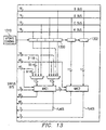
- Figure 13 depicts a simplified block diagram depicting bus interconnections and shadow registers for a dual MAC arrangement in an alternative embodiment of the present invention.
- separate shadow registers 1300 and 1302 are provided for each MAC unit.
- Update control circuitry 1310 provides gated clock signals to each shadow register in response to an associated memory request. Whenever an indirect memory access through the CDP is requested and a redundant coefficient data access is inhibited, as discussed above, update control circuitry 1310 inhibits assertion of a gated clock to the respective shadow register so that the previous data is retained in the respective shadow register 1300, 1302.
- Table 6 is an instruction loop that illustrates elimination of redundant operand fetches for 100% of the coefficient accesses. This could be for Echo cancellation in a wireless telephone, for example.
- Table 7 is an instruction loop that illustrates elimination of redundant operand fetches for 50% of the coefficient accesses. This could be for GSM Half Rate calculations in a wireless telephone, for example.
- Table 8 is an instruction loop that illustrates elimination of redundant operand fetches for 100% of the coefficient accesses. This could be for GSM enhanced Full Rate calculations in a wireless telephone, for example.
- Table 9 is an instruction loop that illustrates elimination of redundant operand fetches for 11% of the coefficient accesses. This could be for GSM Fill Rate calculations in a wireless telephone, for example.
- Figure 14A illustrates an exemplary implementation of an example of such an integrated circuit in a mobile telecommunications device, such as a wireless telephone with integrated keyboard 12 and display 14.
- the digital system 10 with processor 100 is connected to the keyboard 12, where appropriate via a keyboard adapter (not shown), to the display 14, where appropriate via a display adapter (not shown) and to radio frequency (RF) circuitry 16.
- the RF circuitry 16 is connected to an aerial 18.
- Figure 14B is a block diagram representation of the telecommunications device of Figure 14A. Specifically, Figure 14B illustrates the construction of a wireless communications system, namely a digital cellular telephone handset 200. It is contemplated, of course, that many other types of communications systems and computer systems may also benefit from the present invention, particularly those relying on battery power. Examples of such other computer systems include personal digital assistants (PDAS), portable computers, and the like. As power dissipation is also of concern in desktop and line-powered computer systems and micro-controller applications, particularly from a reliability standpoint, it is also contemplated that the present invention may also provide benefits to such line-powered systems.
- PDAS personal digital assistants
- the present invention may also provide benefits to such line-powered systems.
- Handset 226 includes microphone M for receiving audio input, and speaker S for outputting audible output, in the conventional manner.
- Microphone M and speaker S are connected to audio interface 228 which, in this example, converts received signals into digital form and vice versa.
- audio input received at microphone M is processed by filter 230 and analog-to-digital converter (ADC) 232.
- ADC analog-to-digital converter
- digital signals are processed by digital-to-analog converter (DAC) 234 and filter 236, with the results applied to amplifier 238 for output at speaker S.
- ADC analog-to-digital converter
- DAC digital-to-analog converter
- Digital interface 240 is connected to micro-controller 242 and to digital signal processor (DSP) 190.
- DSP 100 of Figure 1 could be used in lieu of DSP 190, connected to micro-controller 242 and to digital interface 240 by way of separate buses as in the example of Figure 6.
- Micro-controller 242 controls the general operation of handset 226 in response to input/output devices 244, examples of which include a keypad or keyboard, a user display, and add-on cards such as a SIM card. Micro-controller 242 also manages other functions such as connection, radio resources, power source monitoring, and the like.
- circuitry used in general operation of handset 226, such as voltage regulators, power sources, operational amplifiers, clock and timing circuitry, switches and the like are not illustrated in Figure 14B for clarity; it is contemplated that those of ordinary skill in the art will readily understand the architecture of handset 226 from this description.
- DSP 190 is connected on one side to interface 240 for communication of signals to and from audio interface 228 (and thus microphone M and speaker S), and on another side to radio frequency (RF) circuitry 246, which transmits and receives radio signals via antenna A.
- RF radio frequency
- Conventional signal processing performed by DSP 190 may include speech coding and decoding, error correction, channel coding and decoding, equalization, demodulation, encryption, voice dialing, echo cancellation, and other similar functions to be performed by handset 190.
- RF circuitry 246 bidirectionally communicates signals between antenna A and DSP 190.
- RF circuitry 246 includes codec 248 that codes the digital signals into the appropriate form for application to modulator 250.
- Modulator 250 in combination with synthesizer circuitry (not shown), generates modulated signals corresponding to the coded digital audio signals; driver 252 amplifies the modulated signals and transmits the same via antenna A. Receipt of signals from antenna A is effected by receiver 254, which applies the received signals to codec 248 for decoding into digital form, application to DSP 190, and eventual communication, via audio interface 228, to speaker S.
- Fabrication of data processing device 100 involves multiple steps of implanting various amounts of impurities into a semiconductor substrate and diffusing the impurities to selected depths within the substrate to form transistor devices. Masks are formed to control the placement of the impurities. Multiple layers of conductive material and insulative material are deposited and etched to interconnect the various devices. These steps are performed in a clean room environment.
- a significant portion of the cost of producing the data processing device involves testing. While in wafer form, individual devices are biased to an operational state and probe tested for basic operational functionality. The wafer is then separated into individual dice which may be sold as bare die or packaged. After packaging, finished parts are biased into an operational state and tested for operational functionality.
- An alternative embodiment of the present invention may include other circuitries that are combined with the circuitries disclosed herein in order to reduce the total gate count of the combined functions. Since those skilled in the art are aware of techniques for gate minimization, the details of such an embodiment will not be described herein.
- the processor includes an instruction buffer unit, and a data computation unit for executing the instructions decoded by the instruction buffer unit. Instructions can be executed in a parallel manner, either in response to implicit parallelism or in response to user defined parallelism.
- coefficient fetches from memory are minimized in either a single MAC embodiment or in a dual MAC embodiment in order to reduce power consumption.
- redundant memory accesses for a reused coefficient data value are eliminated, thereby preserving memory bandwidth and eliminating memory conflicts and thereby improving processing speed.
- the power consumption similar to a register based coefficient operation is provided with increased flexibility.
- a touch instruction "mar(*CDP)" is provided to flag that a coefficient has been updated from a memory write so that the updated coefficient can be fetched for use by the MAC.
- an override mechanism is provided to disable the power saving scheme for debug purposes.
- coefficient data pointer modification tracking circuitry can be simplified by only tracking pointer modification during looping operations.
- connection means electrically connected, including where additional elements may be in the electrical connection path.
- additional tracking circuitry may be provided to monitor the modified status of the CDP at other times than just during a loop or repeated instruction.
- the CDP may be monitored directly such that a modification resulting from a memory mapped write of the CDP is monitored.
- additional monitoring circuitry may be provided to determine if a memory location pointed to by the CDP is modified by an extraneous memory write cycle so that the CDP tracking circuitry can be notified so that a modified coefficient is fetched, instead of the fetch being inhibited. This could occur in response to a memory write by a peripheral device or a communication channel, for instance.
- tracking circuitry may be provided to inhibit redundant memory accesses for an execution unit other than a MAC unit.
Landscapes
- Engineering & Computer Science (AREA)
- Software Systems (AREA)
- Theoretical Computer Science (AREA)
- Physics & Mathematics (AREA)
- General Engineering & Computer Science (AREA)
- General Physics & Mathematics (AREA)
- Executing Machine-Instructions (AREA)
- Advance Control (AREA)
- Complex Calculations (AREA)
Priority Applications (3)
| Application Number | Priority Date | Filing Date | Title |
|---|---|---|---|
| EP00400687A EP1160662A1 (de) | 2000-03-10 | 2000-03-10 | Prozessor mit Verfolgen von Zeiger zur Eliminierung redundanter Speicherabholung |
| US09/716,493 US6826679B1 (en) | 2000-03-10 | 2000-11-20 | Processor with pointer tracking to eliminate redundant memory fetches |
| JP2001066764A JP2001290644A (ja) | 2000-03-10 | 2001-03-09 | マイクロプロセッサを有するディジタル・システム及びそのディジタル・システムを動作させる方法 |
Applications Claiming Priority (1)
| Application Number | Priority Date | Filing Date | Title |
|---|---|---|---|
| EP00400687A EP1160662A1 (de) | 2000-03-10 | 2000-03-10 | Prozessor mit Verfolgen von Zeiger zur Eliminierung redundanter Speicherabholung |
Publications (1)
| Publication Number | Publication Date |
|---|---|
| EP1160662A1 true EP1160662A1 (de) | 2001-12-05 |
Family
ID=8173594
Family Applications (1)
| Application Number | Title | Priority Date | Filing Date |
|---|---|---|---|
| EP00400687A Withdrawn EP1160662A1 (de) | 2000-03-10 | 2000-03-10 | Prozessor mit Verfolgen von Zeiger zur Eliminierung redundanter Speicherabholung |
Country Status (3)
| Country | Link |
|---|---|
| US (1) | US6826679B1 (de) |
| EP (1) | EP1160662A1 (de) |
| JP (1) | JP2001290644A (de) |
Families Citing this family (19)
| Publication number | Priority date | Publication date | Assignee | Title |
|---|---|---|---|---|
| US7346881B2 (en) * | 2002-05-13 | 2008-03-18 | Tensilica, Inc. | Method and apparatus for adding advanced instructions in an extensible processor architecture |
| US7937559B1 (en) | 2002-05-13 | 2011-05-03 | Tensilica, Inc. | System and method for generating a configurable processor supporting a user-defined plurality of instruction sizes |
| US7376812B1 (en) * | 2002-05-13 | 2008-05-20 | Tensilica, Inc. | Vector co-processor for configurable and extensible processor architecture |
| DE10329680A1 (de) * | 2003-07-01 | 2005-02-10 | Universität Stuttgart | Prozessorarchitektur für exakte Zeigeridentifizierung |
| JP2007500393A (ja) * | 2003-07-30 | 2007-01-11 | コーニンクレッカ フィリップス エレクトロニクス エヌ ヴィ | ポインタのアドレスがメモリ・ロケーションの1つにも格納される、単一サイクル・ポインタ・アドレス指定を可能にするメモリ機構 |
| US7308571B2 (en) * | 2004-10-06 | 2007-12-11 | Intel Corporation | Overriding processor configuration settings |
| US20080229074A1 (en) * | 2006-06-19 | 2008-09-18 | International Business Machines Corporation | Design Structure for Localized Control Caching Resulting in Power Efficient Control Logic |
| US20070294519A1 (en) * | 2006-06-19 | 2007-12-20 | Miller Laura F | Localized Control Caching Resulting In Power Efficient Control Logic |
| KR100835173B1 (ko) * | 2006-09-20 | 2008-06-05 | 한국전자통신연구원 | 곱셈 누적 연산을 위한 디지털 신호처리 장치 및 방법 |
| US8280940B2 (en) * | 2007-10-22 | 2012-10-02 | Himax Technologies Limited | Data processing apparatus with shadow register and method thereof |
| US8458439B2 (en) * | 2008-12-16 | 2013-06-04 | International Business Machines Corporation | Block driven computation using a caching policy specified in an operand data structure |
| US8285971B2 (en) * | 2008-12-16 | 2012-10-09 | International Business Machines Corporation | Block driven computation with an address generation accelerator |
| US8407680B2 (en) * | 2008-12-16 | 2013-03-26 | International Business Machines Corporation | Operand data structure for block computation |
| US8327345B2 (en) * | 2008-12-16 | 2012-12-04 | International Business Machines Corporation | Computation table for block computation |
| US8281106B2 (en) * | 2008-12-16 | 2012-10-02 | International Business Machines Corporation | Specifying an addressing relationship in an operand data structure |
| US10152452B2 (en) | 2015-05-29 | 2018-12-11 | Intel Corporation | Source operand read suppression for graphics processors |
| US10540178B2 (en) * | 2016-09-14 | 2020-01-21 | Intel Corporation | Eliminating redundant stores using a protection designator and a clear designator |
| US12061910B2 (en) * | 2019-12-05 | 2024-08-13 | International Business Machines Corporation | Dispatching multiply and accumulate operations based on accumulator register index number |
| US11775457B1 (en) * | 2021-02-23 | 2023-10-03 | Xilinx, Inc. | Command pattern sequencer for memory calibration |
Citations (3)
| Publication number | Priority date | Publication date | Assignee | Title |
|---|---|---|---|---|
| WO1983004137A1 (en) | 1982-05-10 | 1983-11-24 | Ncr Corporation | Memory addressing system |
| US5357618A (en) * | 1991-04-15 | 1994-10-18 | International Business Machines Corporation | Cache prefetch and bypass using stride registers |
| EP0723221A2 (de) | 1995-01-20 | 1996-07-24 | Hitachi, Ltd. | Datenverarbeitungsvorrichtung zur Vorziehen einer Datenstruktur aus dem Hauptspeicher oder seinem Cachespeicher |
Family Cites Families (9)
| Publication number | Priority date | Publication date | Assignee | Title |
|---|---|---|---|---|
| US4531200A (en) * | 1982-12-02 | 1985-07-23 | International Business Machines Corporation | Indexed-indirect addressing using prefix codes |
| DE3740834A1 (de) * | 1987-01-22 | 1988-08-04 | Nat Semiconductor Corp | Aufrechterhaltung der kohaerenz zwischen einem mikroprozessorenintegrierten cache-speicher und einem externen speicher |
| JPH04143819A (ja) | 1989-12-15 | 1992-05-18 | Hitachi Ltd | 消費電力制御方法、半導体集積回路装置およびマイクロプロセツサ |
| US5623615A (en) * | 1994-08-04 | 1997-04-22 | International Business Machines Corporation | Circuit and method for reducing prefetch cycles on microprocessors |
| US5649137A (en) * | 1994-10-20 | 1997-07-15 | Advanced Micro Devices, Inc. | Method and apparatus for store-into-instruction-stream detection and maintaining branch prediction cache consistency |
| US5832257A (en) * | 1995-12-29 | 1998-11-03 | Atmel Corporation | Digital signal processing method and system employing separate program and data memories to store data |
| US5919256A (en) * | 1996-03-26 | 1999-07-06 | Advanced Micro Devices, Inc. | Operand cache addressed by the instruction address for reducing latency of read instruction |
| US5923705A (en) * | 1996-07-18 | 1999-07-13 | Qualcomm Incorporated | UART based autobauding without data loss |
| JP2000099366A (ja) * | 1998-09-21 | 2000-04-07 | Fujitsu Ltd | 演算処理装置および演算処理装置のデバッグ方法 |
-
2000
- 2000-03-10 EP EP00400687A patent/EP1160662A1/de not_active Withdrawn
- 2000-11-20 US US09/716,493 patent/US6826679B1/en not_active Expired - Lifetime
-
2001
- 2001-03-09 JP JP2001066764A patent/JP2001290644A/ja not_active Abandoned
Patent Citations (3)
| Publication number | Priority date | Publication date | Assignee | Title |
|---|---|---|---|---|
| WO1983004137A1 (en) | 1982-05-10 | 1983-11-24 | Ncr Corporation | Memory addressing system |
| US5357618A (en) * | 1991-04-15 | 1994-10-18 | International Business Machines Corporation | Cache prefetch and bypass using stride registers |
| EP0723221A2 (de) | 1995-01-20 | 1996-07-24 | Hitachi, Ltd. | Datenverarbeitungsvorrichtung zur Vorziehen einer Datenstruktur aus dem Hauptspeicher oder seinem Cachespeicher |
Non-Patent Citations (2)
| Title |
|---|
| "METHODS OF SPECIFYING DATA PREFETCHING WITHOUT USING A SEPARATE INSTRUCTION", IBM TECHNICAL DISCLOSURE BULLETIN,US,IBM CORP. NEW YORK, vol. 38, no. 6, 1 June 1995 (1995-06-01), pages 355 - 356, XP000520692, ISSN: 0018-8689 * |
| BERGEY, JR.: "Increased computer throughput by conditioned memory data prefetching", IBM TECHNICAL DISCLOSURE BULLETIN., vol. 20, no. 10, March 1978 (1978-03-01), IBM CORP. NEW YORK., US, pages 4103, XP002142900, ISSN: 0018-8689 * |
Also Published As
| Publication number | Publication date |
|---|---|
| JP2001290644A (ja) | 2001-10-19 |
| US6826679B1 (en) | 2004-11-30 |
Similar Documents
| Publication | Publication Date | Title |
|---|---|---|
| US6826679B1 (en) | Processor with pointer tracking to eliminate redundant memory fetches | |
| US6810475B1 (en) | Processor with pipeline conflict resolution using distributed arbitration and shadow registers | |
| US6795930B1 (en) | Microprocessor with selected partitions disabled during block repeat | |
| US6507921B1 (en) | Trace fifo management | |
| EP0992906B1 (de) | Vorrichtung und Verfahren für einen Software-Haltepunkt während eines Verzögerungsschlitzes | |
| US6363470B1 (en) | Circular buffer management | |
| US6990570B2 (en) | Processor with a computer repeat instruction | |
| US7035985B2 (en) | Method and apparatus for accessing a memory core multiple times in a single clock cycle | |
| EP0992894A1 (de) | Verfahren und Vorrichtung zur Ausführung von Schleifen | |
| US6502152B1 (en) | Dual interrupt vector mapping | |
| US6598151B1 (en) | Stack Pointer Management | |
| JP4355410B2 (ja) | 線形ベクトル計算 | |
| US6499098B1 (en) | Processor with instruction qualifiers to control MMU operation | |
| US6681319B1 (en) | Dual access instruction and compound memory access instruction with compatible address fields | |
| EP0992889A1 (de) | Unterbrechnungsverarbeitung während iterativer Befehlsausführung | |
| EP0992888B1 (de) | Verfahren und Vorrichtung zur iterativen Befehlsausführung | |
| JP2000200212A (ja) | 巡回バッファ管理 | |
| EP0992892A1 (de) | Verbundspeicherzugriffsbefehle | |
| EP0992902A2 (de) | Doppelte Unterbrechungsvektorabbildung | |
| EP1031988A1 (de) | Verfahren und Vorrichtung zum Zugriff auf einen Speicherkern | |
| EP0992881A1 (de) | Ein aufgeteilter Stapel | |
| JP2000267851A (ja) | デジタルシステムおよびその動作方法 | |
| JP2000276352A (ja) | パイプライン保護 | |
| JP2000284966A (ja) | スタック・ポインタ管理 | |
| EP0992890A2 (de) | Prozessor |
Legal Events
| Date | Code | Title | Description |
|---|---|---|---|
| PUAI | Public reference made under article 153(3) epc to a published international application that has entered the european phase |
Free format text: ORIGINAL CODE: 0009012 |
|
| AK | Designated contracting states |
Kind code of ref document: A1 Designated state(s): DE FR GB Kind code of ref document: A1 Designated state(s): AT BE CH CY DE DK ES FI FR GB GR IE IT LI LU MC NL PT SE |
|
| AX | Request for extension of the european patent |
Free format text: AL;LT;LV;MK;RO;SI |
|
| 17P | Request for examination filed |
Effective date: 20020605 |
|
| R17P | Request for examination filed (corrected) |
Effective date: 20020521 |
|
| AKX | Designation fees paid |
Free format text: DE FR GB |
|
| 17Q | First examination report despatched |
Effective date: 20070530 |
|
| STAA | Information on the status of an ep patent application or granted ep patent |
Free format text: STATUS: THE APPLICATION HAS BEEN WITHDRAWN |
|
| 18W | Application withdrawn |
Effective date: 20120914 |