EP1160502A2 - Verbesserte Struktur für eine Lichtinstallation - Google Patents
Verbesserte Struktur für eine Lichtinstallation Download PDFInfo
- Publication number
- EP1160502A2 EP1160502A2 EP00126734A EP00126734A EP1160502A2 EP 1160502 A2 EP1160502 A2 EP 1160502A2 EP 00126734 A EP00126734 A EP 00126734A EP 00126734 A EP00126734 A EP 00126734A EP 1160502 A2 EP1160502 A2 EP 1160502A2
- Authority
- EP
- European Patent Office
- Prior art keywords
- conductors
- lamp tube
- transparent lamp
- lights
- light installation
- Prior art date
- Legal status (The legal status is an assumption and is not a legal conclusion. Google has not performed a legal analysis and makes no representation as to the accuracy of the status listed.)
- Granted
Links
- 238000009434 installation Methods 0.000 title claims description 28
- 239000004020 conductor Substances 0.000 claims description 54
- 239000011248 coating agent Substances 0.000 claims description 3
- 238000000576 coating method Methods 0.000 claims description 3
- 239000000463 material Substances 0.000 description 3
- 238000003780 insertion Methods 0.000 description 2
- 230000037431 insertion Effects 0.000 description 2
- 238000000465 moulding Methods 0.000 description 2
- 239000000047 product Substances 0.000 description 2
- 230000004323 axial length Effects 0.000 description 1
- 230000001010 compromised effect Effects 0.000 description 1
- 238000005034 decoration Methods 0.000 description 1
- 238000005516 engineering process Methods 0.000 description 1
- 238000004519 manufacturing process Methods 0.000 description 1
- 238000012986 modification Methods 0.000 description 1
- 230000004048 modification Effects 0.000 description 1
- 239000011265 semifinished product Substances 0.000 description 1
Images


Classifications
-
- F—MECHANICAL ENGINEERING; LIGHTING; HEATING; WEAPONS; BLASTING
- F21—LIGHTING
- F21S—NON-PORTABLE LIGHTING DEVICES; SYSTEMS THEREOF; VEHICLE LIGHTING DEVICES SPECIALLY ADAPTED FOR VEHICLE EXTERIORS
- F21S4/00—Lighting devices or systems using a string or strip of light sources
- F21S4/20—Lighting devices or systems using a string or strip of light sources with light sources held by or within elongate supports
Definitions
- the present invention relates to an improved structure for a Light installation and in particular on a connection structure for a number of in such a light installation located fairy lights, the structure still corresponds to higher security requirements. Even with a light installation with one Number of fairy lights of different lengths can be the total outside diameter the light installation can be effectively reduced.
- a light installation or light chain system comprises more than one light chain, where a flexible and transparent tube glows or flashes when passing through a Circuit on the chain of lights is activated.
- a flexible light installation can for decoration purposes over the area in question (such as a wall of a Building) and can be made in the form of a roll is cut to the desired length for later use receive.
- the basic structure of such a tubular light installation includes one for this necessary conductors and a number of lamp bulbs that form the fairy lights.
- a number of in one pipe arranged lamp bulbs there are two types, of which the a number of radial holes alternately arranged on the tube and the other has a number of axial grooves arranged on the tube.
- the conductors for connecting the fairy lights are in one piece at the desired location the transparent tube (generally made of PVC material).
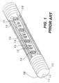
- Fig. 1 In the above structure of light installations with a number of radial Holes for arranging the lamp bulbs as shown in Fig. 1 can be one Number of conductors 11, 12, 13 arranged simultaneously in a transparent tube 10 if the latter is made from PVC material. Has such a structure two fairy lights in the tube; it therefore contains a common power supply line 11 and two connecting conductors 12, 13.
- the tube with the conductors is designed so that there is a Number of radial holes.
- This product has a larger radial one at the beginning Hole that allows the insertion of a bulb 14 from each string of lights, then two smaller radial holes next to this hole, which is the insertion of two Allow connecting devices 15, then again a larger radial hole, then again two more smaller radial holes etc.
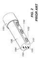
- the light installation of Fig. 2 has a number of axial grooves for arranging the String of lights, with an elongated groove 101 axially on a transparent tube 100 is provided to have a string of lights with a number of lamp bulbs 102 therein to use.
- a number of conductors 103, 104, 105 are all on one side of the elongated groove 101 arranged.
- Such a conventional light installation structure is similarly inconvenient because it has a number of string lights that are in one single elongated roller 101 must be arranged, and since the conductors 104, 105 too are arranged close to the outer edge of the transparent tube 100, whereby the Security is compromised. Since the ladder is all on one side of the elongated groove 101 the diameter of the entire light installation is increased, which negatively affects their function and drives up costs become.
- the object of the present invention to provide an improved structure for a To provide light installation, the transparent tube of which is formed directly with a Number of axial elongated grooves for receiving the corresponding amount of Fairy lights are provided, with a common conductor and a number of individual conductors are arranged so that between the common conductor and each of the individual conductors runs one of the elongated grooves in the transparent tube, so that each string of lights is arranged in one of the elongated grooves.
- Such one Semi-finished product is then made with a secure positioning layer with minimal Provide diameter and then with a coating with minimal thickness covered, creating an improved structure for a light installation with a larger amount of inner fairy lights and a smaller outer diameter is provided which is more suitable for assembly and higher Security requirements met.
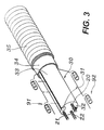
- the present invention includes a transparent one Lamp tube 30, which can be made of PVC material, the transparent Lamp tube 30 can be designed so that there are axial elongated grooves 31, 32 for Includes the required amount of fairy lights.
- a number of Conductors 20, 21 and 22 are in the transparent lamp tube 30 at the same time in the case of molds intended.
- the above-mentioned embodiment has two in the transparent lamp tube 30 Fairy lights 91, 92 on.
- the elongated grooves 31, 32 are therefore 180 ° apart and the conductors comprise a common conductor 20 and two individual ones Conductors 21, 22.
- Such an arrangement of the conductors 20, 21 and 22 in the transparent Lamp tube 30 causes the conductors to be the greatest distance from the outer edge 33 of the transparent lamp tube 30.
- the two string lights 91, 92 can be inserted into the two axial elongated grooves 31, 32 are used. Then on the outer edge of the transparent lamp tube 30 a positioning layer 34 with a minimal Diameter applied, finally, this is a transparent Coating 35 covered with a minimum diameter.
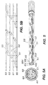
- Figures 5, 5a and 5b show the light installation of the present invention with three in it included fairy lights 51, 52 and 53.
- a transparent lamp tube 300 On a transparent lamp tube 300 are three axial elongated grooves 301, 302 and 303 arranged, each by 120 ° from are spaced from each other.
- the fairy lights 51, 52 and 53 are each in their corresponding axial elongated grooves 301, 302 and 303 arranged.
- a number of conductors 60, 61, 62, and 63 are simultaneously formed in the transparent lamp tube 300 has been arranged, as already described above was so that the conductors 61, 62 and 63 are arranged so that the common conductor 60 and the conductor 61 between them the corresponding axial elongated groove 301 include the common conductor 60 and the conductor 62 between them corresponding axial elongated groove 302 and the common conductor 60 and the conductor 63 the corresponding axial length 303 between them.
- the common conductor 60 is shown in FIG This embodiment is arranged in the middle of the transparent lamp tube 300.
- the conductors 61, 62 and 63 are arranged so that each of them is between two axial elongated grooves.
- Figures 6, 6a and 6b show the light installation of the present Invention with four fairy lights contained therein.
- On the transparent lamp tube there are a corresponding number of elongated axial grooves at a distance of 90 ° to each other to record their respective fairy lights.
- a number of conductors 71, 72, 73 and 74 are simultaneously in the transparent in the molding Lamp tube has been arranged, with the common conductor 70 in the center of the Tube lies and the conductors 71, 72, 73 and 74 each between two axial elongated Grooves.
- each chain of lights lies in a corresponding axial elongated groove, the is Manufacturing very simple, and since the ladder from the outer edge of the transparent Lamp tube are kept away, a higher security standard is met and the entire outer diameter of the light installation - even when using a Large number of fairy lights in the transparent lamp tube - can be effectively reduced, whereby the present invention gains industrial importance.
Landscapes
- Engineering & Computer Science (AREA)
- General Engineering & Computer Science (AREA)
- Non-Portable Lighting Devices Or Systems Thereof (AREA)
- Arrangement Of Elements, Cooling, Sealing, Or The Like Of Lighting Devices (AREA)
- Fastening Of Light Sources Or Lamp Holders (AREA)
- Road Signs Or Road Markings (AREA)
Abstract
Description
- Fig. 1
- ist eine Schrägansicht der Struktur einer herkömmlichen Lichtinstallation;
- Fig. 2
- ist eine Schrägansicht der Struktur einer anderen herkömmlichen Lichtinstallation;
- Fig. 3
- ist eine schematische Ansicht einer bevorzugten Ausführungsform der vorliegenden Erfindung mit zwei Lichterketten;
- Fig. 4
- ist eine strukturelle schematische Ansicht von Fig. 3;
- Fig. 4a
- ist eine Querschnittansicht davon;
- Fig. 4b
- ist eine schematische Ansicht und zeigt die Verbindung der Leiter;
- Fig. 5
- ist eine weitere strukturelle schematische Ansicht der vorliegenden Erfindung mit drei Lichterketten;
- Fig. 6
- ist eine weitere strukturelle Ansicht der vorliegenden Erfindung mit vier Lichterketten;
- Fig. 6a
- ist eine Querschnittsansicht davon;
- Fig. 6b
- ist eine schematische Ansicht und zeigt die Verbindung der Leiter.
Claims (4)
- Verbesserte Struktur für eine Lichtinstallation, umfassend ein einstückig geformtes transparentes Lampenrohr, das mit einer Beschichtung abgedeckt ist,
wobei eine Anzahl von Leitern, bestehend aus einem gemeinsamen Leiter und einer Anzahl von einzelnen Leitern, gleichzeitig beim Formen des transparenten Lampenrohres im transparenten Lampenrohr angeordnet werden,
wobei axiale längliche Rillen in derselben Anzahl wie diejenige der im transparenten Lampenrohr verwendeten Lichterketten zum Aufnehmen einer entsprechenden Lichterkette in gleichem Abstand voneinander auf dem transparenten Lampenrohr angeordnet sind; dabei sind die Leiter so angeordnet, daß jeweils zwei der Leiter nämlich der gemeinsame Leiter und einer der einzelnen Leiter, zwischen sich eine entsprechende der axialen länglichen Rillen einschließen. - Verbesserte Struktur für eine Lichtinstallation nach Anspruch 1,
wobei sich der gemeinsame Leiter auf der einen Seite der axialen länglichen Rillen befindet, während sich die einzelnen Leiter auf der anderen Seite der axialen länglichen Rillen befinden. - Verbesserte Struktur für eine Lichtinstallation nach Anspruch 1,
wobei sich der gemeinsame Leiter in der Mitte des transparenten Lampenrohres befindet, während die einzelnen Leiter so angeordnet sind, daß jeweils zwischen zwei der einzelnen Leiter eine entsprechende axiale längliche Rille verläuft. - Verbesserte Struktur für eine Lichtinstallation nach Anspruch 1,
wobei das transparente Lampenrohr mit den darin befindlichen Lichterketten so ausgebildet ist, daß es eine Positionierschicht mit einem minimalen Durchmesser besitzt, die auf dessen äußerem Rand gebildet ist, sowie eine darauf gebildete Abdeckung aus einer transparenten Schicht mit minimalem Durchmesser.
Applications Claiming Priority (2)
| Application Number | Priority Date | Filing Date | Title |
|---|---|---|---|
| DE20009794U | 2000-05-31 | ||
| DE20009794U DE20009794U1 (de) | 2000-05-26 | 2000-05-31 | Verbesserte Struktur für eine Lichtinstallation |
Publications (3)
| Publication Number | Publication Date |
|---|---|
| EP1160502A2 true EP1160502A2 (de) | 2001-12-05 |
| EP1160502A3 EP1160502A3 (de) | 2004-04-07 |
| EP1160502B1 EP1160502B1 (de) | 2006-11-02 |
Family
ID=7942284
Family Applications (1)
| Application Number | Title | Priority Date | Filing Date |
|---|---|---|---|
| EP00126734A Expired - Lifetime EP1160502B1 (de) | 2000-05-31 | 2000-12-06 | Verbesserte Struktur für eine Lichtinstallation |
Country Status (4)
| Country | Link |
|---|---|
| EP (1) | EP1160502B1 (de) |
| AT (1) | ATE344420T1 (de) |
| DE (1) | DE50013692D1 (de) |
| ES (1) | ES2275468T3 (de) |
Cited By (1)
| Publication number | Priority date | Publication date | Assignee | Title |
|---|---|---|---|---|
| EP1318348A1 (de) * | 2001-12-10 | 2003-06-11 | Tsui-Tuan Fan Wong | Farbvolle, dekorative Leuchte |
Family Cites Families (3)
| Publication number | Priority date | Publication date | Assignee | Title |
|---|---|---|---|---|
| FR2407796A1 (fr) * | 1977-11-07 | 1979-06-01 | Anquetin Jacques | Dispositif permettant de rechercher et de saisir des pieces metalliques a des endroits d'acces difficile |
| US4812956A (en) * | 1987-03-05 | 1989-03-14 | Tien Teng Wang | Flexible lamp-string device |
| US5934792A (en) * | 1997-02-24 | 1999-08-10 | Itc, Inc. | Flexible lighting system |
-
2000
- 2000-12-06 AT AT00126734T patent/ATE344420T1/de not_active IP Right Cessation
- 2000-12-06 DE DE50013692T patent/DE50013692D1/de not_active Expired - Fee Related
- 2000-12-06 ES ES00126734T patent/ES2275468T3/es not_active Expired - Lifetime
- 2000-12-06 EP EP00126734A patent/EP1160502B1/de not_active Expired - Lifetime
Non-Patent Citations (1)
| Title |
|---|
| None |
Cited By (1)
| Publication number | Priority date | Publication date | Assignee | Title |
|---|---|---|---|---|
| EP1318348A1 (de) * | 2001-12-10 | 2003-06-11 | Tsui-Tuan Fan Wong | Farbvolle, dekorative Leuchte |
Also Published As
| Publication number | Publication date |
|---|---|
| EP1160502B1 (de) | 2006-11-02 |
| ATE344420T1 (de) | 2006-11-15 |
| EP1160502A3 (de) | 2004-04-07 |
| DE50013692D1 (de) | 2006-12-14 |
| ES2275468T3 (es) | 2007-06-16 |
Similar Documents
| Publication | Publication Date | Title |
|---|---|---|
| DE20009794U1 (de) | Verbesserte Struktur für eine Lichtinstallation | |
| DE2457316C2 (de) | Ejektorvorrichtung | |
| DE2728971C3 (de) | Einsatz für ein Wärmetauscherrohr | |
| EP2443352B1 (de) | Profilstabverbindungssystem | |
| DE102017114925B4 (de) | Langfeldleuchte mit lichttechnischer Abdeckung | |
| EP4573314A1 (de) | Profilanordnung zum aufbauen von ausstellungsständen oder ladeneinrichtungen | |
| EP2264363A1 (de) | Leuchte, Endkappe und Lichtband | |
| DE19801954B4 (de) | Leuchtensystem | |
| EP1160502B1 (de) | Verbesserte Struktur für eine Lichtinstallation | |
| WO2018137948A1 (de) | Verfahren zum herstellen eines led-bandes | |
| DE29803723U1 (de) | Lichtleistensystem | |
| DE20009797U1 (de) | Endverbindungsstruktur für eine Lichtinstallation | |
| DE3223646A1 (de) | Rohrmontagesystem fuer leer- und lichtrohre | |
| DE1683143B1 (de) | Mehrteiliger formkern der aus einzelnen geraden rechtwinke lig aufeinander stehenden abschnitten zusammengesetzt ist | |
| DE29900384U1 (de) | Schmückende Beleuchtungsvorrichtung mit einem flexibel formbaren Lichtemissionsschlauch, wodurch vom Benutzer konzipierte Zeichen blinkend anzeigbar sind | |
| DE1572485A1 (de) | Schalldaempfer | |
| DE29912612U1 (de) | Kettenförmige Lampe | |
| DE202005003464U1 (de) | Gitterwandgestell | |
| DE202015009707U1 (de) | Tür- und/oder Fensterbeschlag-Befestigungsvorrichtung | |
| DE2549988B2 (de) | Kreiszylindrisches Stangenprofil zum Anschließen und Verbinden von Bauteilen, insbesondere für Möbel, Gestelle o.dgl | |
| EP2522902A1 (de) | Leuchtmontagesystem für Gebäude | |
| EP1519103B1 (de) | Leuchte mit rohrförmiger Gasentladungslampe | |
| DE2753636C2 (de) | ||
| DE102019210025B4 (de) | Lichteinsatz, Verfahren zu dessen Herstellung und Beleuchtungssystem | |
| DE2114139C2 (de) | Gitterwerk für Mosaik-Leuchtschaltbilder |
Legal Events
| Date | Code | Title | Description |
|---|---|---|---|
| PUAI | Public reference made under article 153(3) epc to a published international application that has entered the european phase |
Free format text: ORIGINAL CODE: 0009012 |
|
| AK | Designated contracting states |
Kind code of ref document: A2 Designated state(s): AT BE CH CY DE DK ES FI FR GB GR IE IT LI LU MC NL PT SE TR |
|
| AX | Request for extension of the european patent |
Free format text: AL;LT;LV;MK;RO;SI |
|
| PUAL | Search report despatched |
Free format text: ORIGINAL CODE: 0009013 |
|
| AK | Designated contracting states |
Kind code of ref document: A3 Designated state(s): AT BE CH CY DE DK ES FI FR GB GR IE IT LI LU MC NL PT SE TR |
|
| AX | Request for extension of the european patent |
Extension state: AL LT LV MK RO SI |
|
| 17P | Request for examination filed |
Effective date: 20040709 |
|
| AKX | Designation fees paid |
Designated state(s): AT BE CH CY DE DK ES FI FR GB GR IE IT LI LU MC NL PT SE TR |
|
| 17Q | First examination report despatched |
Effective date: 20050107 |
|
| GRAP | Despatch of communication of intention to grant a patent |
Free format text: ORIGINAL CODE: EPIDOSNIGR1 |
|
| RIC1 | Information provided on ipc code assigned before grant |
Ipc: F21W 121/00 20060101ALN20060526BHEP Ipc: F21S 4/00 20060101AFI20060526BHEP |
|
| GRAS | Grant fee paid |
Free format text: ORIGINAL CODE: EPIDOSNIGR3 |
|
| GRAA | (expected) grant |
Free format text: ORIGINAL CODE: 0009210 |
|
| AK | Designated contracting states |
Kind code of ref document: B1 Designated state(s): AT BE CH CY DE DK ES FI FR GB GR IE IT LI LU MC NL PT SE TR |
|
| PG25 | Lapsed in a contracting state [announced via postgrant information from national office to epo] |
Ref country code: FI Free format text: LAPSE BECAUSE OF FAILURE TO SUBMIT A TRANSLATION OF THE DESCRIPTION OR TO PAY THE FEE WITHIN THE PRESCRIBED TIME-LIMIT Effective date: 20061102 |
|
| REG | Reference to a national code |
Ref country code: GB Ref legal event code: FG4D Free format text: NOT ENGLISH |
|
| REG | Reference to a national code |
Ref country code: IE Ref legal event code: FG4D Free format text: LANGUAGE OF EP DOCUMENT: GERMAN |
|
| REG | Reference to a national code |
Ref country code: CH Ref legal event code: EP |
|
| REF | Corresponds to: |
Ref document number: 50013692 Country of ref document: DE Date of ref document: 20061214 Kind code of ref document: P |
|
| PG25 | Lapsed in a contracting state [announced via postgrant information from national office to epo] |
Ref country code: MC Free format text: LAPSE BECAUSE OF NON-PAYMENT OF DUE FEES Effective date: 20061231 |
|
| PGFP | Annual fee paid to national office [announced via postgrant information from national office to epo] |
Ref country code: IT Payment date: 20061231 Year of fee payment: 7 |
|
| PGFP | Annual fee paid to national office [announced via postgrant information from national office to epo] |
Ref country code: DE Payment date: 20070109 Year of fee payment: 7 |
|
| PGFP | Annual fee paid to national office [announced via postgrant information from national office to epo] |
Ref country code: AT Payment date: 20070110 Year of fee payment: 7 |
|
| PGFP | Annual fee paid to national office [announced via postgrant information from national office to epo] |
Ref country code: SE Payment date: 20070115 Year of fee payment: 7 |
|
| PGFP | Annual fee paid to national office [announced via postgrant information from national office to epo] |
Ref country code: NL Payment date: 20070118 Year of fee payment: 7 |
|
| PGFP | Annual fee paid to national office [announced via postgrant information from national office to epo] |
Ref country code: IE Payment date: 20070123 Year of fee payment: 7 |
|
| PGFP | Annual fee paid to national office [announced via postgrant information from national office to epo] |
Ref country code: CH Payment date: 20070124 Year of fee payment: 7 Ref country code: ES Payment date: 20070124 Year of fee payment: 7 |
|
| PGFP | Annual fee paid to national office [announced via postgrant information from national office to epo] |
Ref country code: BE Payment date: 20070126 Year of fee payment: 7 |
|
| PG25 | Lapsed in a contracting state [announced via postgrant information from national office to epo] |
Ref country code: DK Free format text: LAPSE BECAUSE OF FAILURE TO SUBMIT A TRANSLATION OF THE DESCRIPTION OR TO PAY THE FEE WITHIN THE PRESCRIBED TIME-LIMIT Effective date: 20070202 |
|
| PGFP | Annual fee paid to national office [announced via postgrant information from national office to epo] |
Ref country code: GB Payment date: 20070202 Year of fee payment: 7 |
|
| REG | Reference to a national code |
Ref country code: SE Ref legal event code: TRGR |
|
| GBT | Gb: translation of ep patent filed (gb section 77(6)(a)/1977) |
Effective date: 20070214 |
|
| PG25 | Lapsed in a contracting state [announced via postgrant information from national office to epo] |
Ref country code: PT Free format text: LAPSE BECAUSE OF FAILURE TO SUBMIT A TRANSLATION OF THE DESCRIPTION OR TO PAY THE FEE WITHIN THE PRESCRIBED TIME-LIMIT Effective date: 20070402 |
|
| REG | Reference to a national code |
Ref country code: CH Ref legal event code: NV Representative=s name: FREI PATENTANWALTSBUERO AG |
|
| ET | Fr: translation filed | ||
| REG | Reference to a national code |
Ref country code: ES Ref legal event code: FG2A Ref document number: 2275468 Country of ref document: ES Kind code of ref document: T3 |
|
| PLBE | No opposition filed within time limit |
Free format text: ORIGINAL CODE: 0009261 |
|
| STAA | Information on the status of an ep patent application or granted ep patent |
Free format text: STATUS: NO OPPOSITION FILED WITHIN TIME LIMIT |
|
| 26N | No opposition filed |
Effective date: 20070803 |
|
| PG25 | Lapsed in a contracting state [announced via postgrant information from national office to epo] |
Ref country code: GR Free format text: LAPSE BECAUSE OF FAILURE TO SUBMIT A TRANSLATION OF THE DESCRIPTION OR TO PAY THE FEE WITHIN THE PRESCRIBED TIME-LIMIT Effective date: 20070203 |
|
| PGFP | Annual fee paid to national office [announced via postgrant information from national office to epo] |
Ref country code: FR Payment date: 20070118 Year of fee payment: 7 |
|
| BERE | Be: lapsed |
Owner name: SHINING BLICK ENTERPRISES CO., LTD. Effective date: 20071231 |
|
| PG25 | Lapsed in a contracting state [announced via postgrant information from national office to epo] |
Ref country code: TR Free format text: LAPSE BECAUSE OF FAILURE TO SUBMIT A TRANSLATION OF THE DESCRIPTION OR TO PAY THE FEE WITHIN THE PRESCRIBED TIME-LIMIT Effective date: 20061102 Ref country code: LU Free format text: LAPSE BECAUSE OF NON-PAYMENT OF DUE FEES Effective date: 20061206 |
|
| REG | Reference to a national code |
Ref country code: CH Ref legal event code: PL |
|
| EUG | Se: european patent has lapsed | ||
| GBPC | Gb: european patent ceased through non-payment of renewal fee |
Effective date: 20071206 |
|
| PG25 | Lapsed in a contracting state [announced via postgrant information from national office to epo] |
Ref country code: AT Free format text: LAPSE BECAUSE OF NON-PAYMENT OF DUE FEES Effective date: 20071206 |
|
| NLV4 | Nl: lapsed or anulled due to non-payment of the annual fee |
Effective date: 20080701 |
|
| PG25 | Lapsed in a contracting state [announced via postgrant information from national office to epo] |
Ref country code: BE Free format text: LAPSE BECAUSE OF NON-PAYMENT OF DUE FEES Effective date: 20071231 |
|
| PG25 | Lapsed in a contracting state [announced via postgrant information from national office to epo] |
Ref country code: CH Free format text: LAPSE BECAUSE OF NON-PAYMENT OF DUE FEES Effective date: 20071231 Ref country code: IE Free format text: LAPSE BECAUSE OF NON-PAYMENT OF DUE FEES Effective date: 20071206 Ref country code: LI Free format text: LAPSE BECAUSE OF NON-PAYMENT OF DUE FEES Effective date: 20071231 Ref country code: DE Free format text: LAPSE BECAUSE OF NON-PAYMENT OF DUE FEES Effective date: 20080701 Ref country code: SE Free format text: LAPSE BECAUSE OF NON-PAYMENT OF DUE FEES Effective date: 20071207 |
|
| REG | Reference to a national code |
Ref country code: FR Ref legal event code: ST Effective date: 20081020 |
|
| PG25 | Lapsed in a contracting state [announced via postgrant information from national office to epo] |
Ref country code: CY Free format text: LAPSE BECAUSE OF FAILURE TO SUBMIT A TRANSLATION OF THE DESCRIPTION OR TO PAY THE FEE WITHIN THE PRESCRIBED TIME-LIMIT Effective date: 20061102 Ref country code: NL Free format text: LAPSE BECAUSE OF NON-PAYMENT OF DUE FEES Effective date: 20080701 |
|
| PG25 | Lapsed in a contracting state [announced via postgrant information from national office to epo] |
Ref country code: GB Free format text: LAPSE BECAUSE OF NON-PAYMENT OF DUE FEES Effective date: 20071206 |
|
| REG | Reference to a national code |
Ref country code: ES Ref legal event code: FD2A Effective date: 20071207 |
|
| PG25 | Lapsed in a contracting state [announced via postgrant information from national office to epo] |
Ref country code: FR Free format text: LAPSE BECAUSE OF NON-PAYMENT OF DUE FEES Effective date: 20071231 Ref country code: ES Free format text: LAPSE BECAUSE OF NON-PAYMENT OF DUE FEES Effective date: 20071207 |
|
| PG25 | Lapsed in a contracting state [announced via postgrant information from national office to epo] |
Ref country code: IT Free format text: LAPSE BECAUSE OF NON-PAYMENT OF DUE FEES Effective date: 20071206 |