EP1159550B1 - Anti-theft brake or clutch pedal locking device - Google Patents
Anti-theft brake or clutch pedal locking device Download PDFInfo
- Publication number
- EP1159550B1 EP1159550B1 EP00916406A EP00916406A EP1159550B1 EP 1159550 B1 EP1159550 B1 EP 1159550B1 EP 00916406 A EP00916406 A EP 00916406A EP 00916406 A EP00916406 A EP 00916406A EP 1159550 B1 EP1159550 B1 EP 1159550B1
- Authority
- EP
- European Patent Office
- Prior art keywords
- vehicle
- lock
- pedal
- leg
- base
- Prior art date
- Legal status (The legal status is an assumption and is not a legal conclusion. Google has not performed a legal analysis and makes no representation as to the accuracy of the status listed.)
- Expired - Lifetime
Links
Images


Classifications
-
- B—PERFORMING OPERATIONS; TRANSPORTING
- B60—VEHICLES IN GENERAL
- B60R—VEHICLES, VEHICLE FITTINGS, OR VEHICLE PARTS, NOT OTHERWISE PROVIDED FOR
- B60R25/00—Fittings or systems for preventing or indicating unauthorised use or theft of vehicles
- B60R25/01—Fittings or systems for preventing or indicating unauthorised use or theft of vehicles operating on vehicle systems or fittings, e.g. on doors, seats or windscreens
- B60R25/02—Fittings or systems for preventing or indicating unauthorised use or theft of vehicles operating on vehicle systems or fittings, e.g. on doors, seats or windscreens operating on the steering mechanism
- B60R25/022—Fittings or systems for preventing or indicating unauthorised use or theft of vehicles operating on vehicle systems or fittings, e.g. on doors, seats or windscreens operating on the steering mechanism operating on the steering wheel, e.g. bars locked to the steering wheel rim
- B60R25/0221—Fittings or systems for preventing or indicating unauthorised use or theft of vehicles operating on vehicle systems or fittings, e.g. on doors, seats or windscreens operating on the steering mechanism operating on the steering wheel, e.g. bars locked to the steering wheel rim restraining means joining the steering wheel with another part of the car, e.g. pedals
-
- B—PERFORMING OPERATIONS; TRANSPORTING
- B60—VEHICLES IN GENERAL
- B60R—VEHICLES, VEHICLE FITTINGS, OR VEHICLE PARTS, NOT OTHERWISE PROVIDED FOR
- B60R25/00—Fittings or systems for preventing or indicating unauthorised use or theft of vehicles
- B60R25/002—Locking of control actuating or transmitting means
- B60R25/003—Locking of control actuating or transmitting means locking of control actuating means
- B60R25/005—Locking of control actuating or transmitting means locking of control actuating means of foot actuated control means
-
- Y—GENERAL TAGGING OF NEW TECHNOLOGICAL DEVELOPMENTS; GENERAL TAGGING OF CROSS-SECTIONAL TECHNOLOGIES SPANNING OVER SEVERAL SECTIONS OF THE IPC; TECHNICAL SUBJECTS COVERED BY FORMER USPC CROSS-REFERENCE ART COLLECTIONS [XRACs] AND DIGESTS
- Y10—TECHNICAL SUBJECTS COVERED BY FORMER USPC
- Y10T—TECHNICAL SUBJECTS COVERED BY FORMER US CLASSIFICATION
- Y10T70/00—Locks
- Y10T70/50—Special application
- Y10T70/5611—For control and machine elements
- Y10T70/569—Lever
- Y10T70/573—Single
- Y10T70/5735—Externally mounted locking device
-
- Y—GENERAL TAGGING OF NEW TECHNOLOGICAL DEVELOPMENTS; GENERAL TAGGING OF CROSS-SECTIONAL TECHNOLOGIES SPANNING OVER SEVERAL SECTIONS OF THE IPC; TECHNICAL SUBJECTS COVERED BY FORMER USPC CROSS-REFERENCE ART COLLECTIONS [XRACs] AND DIGESTS
- Y10—TECHNICAL SUBJECTS COVERED BY FORMER USPC
- Y10T—TECHNICAL SUBJECTS COVERED BY FORMER US CLASSIFICATION
- Y10T70/00—Locks
- Y10T70/50—Special application
- Y10T70/5611—For control and machine elements
- Y10T70/5757—Handle, handwheel or knob
-
- Y—GENERAL TAGGING OF NEW TECHNOLOGICAL DEVELOPMENTS; GENERAL TAGGING OF CROSS-SECTIONAL TECHNOLOGIES SPANNING OVER SEVERAL SECTIONS OF THE IPC; TECHNICAL SUBJECTS COVERED BY FORMER USPC CROSS-REFERENCE ART COLLECTIONS [XRACs] AND DIGESTS
- Y10—TECHNICAL SUBJECTS COVERED BY FORMER USPC
- Y10T—TECHNICAL SUBJECTS COVERED BY FORMER US CLASSIFICATION
- Y10T70/00—Locks
- Y10T70/50—Special application
- Y10T70/5889—For automotive vehicles
Definitions
- This invention relates to anti-theft brake or clutch pedal locking devices for vehicles which are particularly suitable for both automatic and standard transmission vehicles. More particularly, this invention relates to devices which prevent the brake or clutch pedal from being depressed, thereby rendering a vehicle inoperable.
- connection due it longitudinal size and cumbersomeness is difficult to store when the device is not being utilized.
- devices of this nature actually have a poor record against theft. Indeed, it is relatively easy to cut the rim of the steering wheel by means of a saw or the like.
- the rim of the steering wheel is usually not a viable obstacle for thieves, and the anti-theft device by can be disengaged merely pulling apart the two ends of the rim.
- Such devices are also not usually adaptable for automatic transmission vehicles because of their structural characteristics.
- an anti-theft pedal-locking device for vehicles comprising a first supporting member extending upwards and provided with a safety lock and with a laterally projecting member and a second supporting member, upon which the first supporting member slides.
- a projecting member cooperates with the corresponding member of the first supporting member so as to lock a pedal of the vehicle when the latter member is in its lower position, while the lower end of the second supporting member may carry a base member to rest on the floor of the vehicle.
- U.S. Patent No. 4,040,675 discloses a vehicle anti-theft device which maintains the braking function of the braking fluid by preventing reverse flow thereof from the wheel cylinder back to the master cylinder until an authorized procedure permits said backflow.
- U.S. Patent No. 4,493,198 discloses an anti-theft lock for a pedal operated apparatus.
- the invention incorporates first and second stop bodies which are arranged to clamp around the lever of a pedal. When the stop bodies are locked in place, the pedal cannot be operated unless the apparatus is restrained.
- U.S. Patent No. 4,934,492 discloses an automatic brake-locking mechanism which locks the brake of a vehicle having a hydraulic brake system.
- the system incorporates a safety switch provided to operate in conjunction with the ignition switch so that the safety switch and the ignition both must be operated to an "on" position to release the auxiliary brake device to allow normal operation of the vehicle.
- U.S. Patent No. 5,040.387 similarly discloses a vehicle brake lock assembly which engages a brake pedal and which includes a U-shaped end portion which engages the brake pedal telescopically to lock the brake pedal in position.
- U.S. Patent No. 5,345,796 discloses a vehicle brake-pedal locking device which mechanically maintains the vehicle brake pedal in a depressed position to prevent the vehicle from being driven.
- the device includes a horizontally and vertically pivoting brake-pedal swing arm interfacing structure.
- U.S. Patent No. 5,653,133 discloses an anti-theft device for vehicles having a steering wheel and a brake.
- the device comprises a brake guard moveably mounted to a fixed portion of the brake, a lower elongated member which hooks to the brake guard, an upper elongated member which is locked to the lower elongated member, a wide bar spaced a distance adaptable to be placed around the steering wheel and a locking bar and a claw member.
- 5,881,587 published on the priority date of the present application discloses a device for locking the brake of a vehicle and preventing its theft comprising: a base member for a placement on the floorboard of a vehicle beneath a brake pedal; a U-shaped housing extending downward and having a first arm attached to the base and having a second shorter arm defining a gap for receipt of a brake pedal shaft, said space between the first and second arm defining a slot for receiving the brake pedal shaft and permitting its full extension upward through said shaft; and locking means associated with the first arm for locking the underside of the pedal within the slot such that brake pedal cannot be depressed.
- US-A-5 870 912 discloses the features of the preamble of claim 1.
- the present invention is thus directed to a brake pedal or clutch pedal locking mechanism which does not require the driver or vehicle operator to get down on his knees or to move beneath the vehicle and which prevents the brake pedal or clutch pedal from being depressed.
- the invention is a device to lock a brake or clutch pedal of a vehicle so as to deter theft of the vehicle according to claim 1.
- the device comprises: a base for placement on the floor of the vehicle beneath the pedal of the vehicle and a pedal shaft supporting the pedal; a generally U-shaped housing having a second leg attached to the base member, a first leg shorter than the second leg, and a cross member connecting the first and second legs to define an opening between the first leg and the base and a slot between the first and second legs, the opening and slot being sufficiently large to receive the pedal shaft and permit travel of the pedal shaft through the slot; a locking pin selectively movable on the U-shaped housing between a raised position sufficiently close to a lower side of the pedal shaft to prevent the pedal shaft from being depressed sufficiently to enable the vehicle to be started and a retracted position to permit travel of the pedal shaft through the slot and opening; and a lock coupled to the U-shaped housing and operably connected to the locking pin to fix the locking pin in at least the raised position, the lock having an upper face with
- FIGS 1 to 8B show embodiments which are not part of the present invention as claimed.
- the brake anti-theft device of the present invention is now described with reference to the enclosed Figures 9 to 16 wherein the same numbers are utilized where applicable.
- the present invention is a device specifically designed to lock the brake pedal or clutch pedal of a motor vehicle in an up, i.e., non-depressed, state.
- BPSI brake pedal shift interlock
- CPSI clutch pedal start interlock
- the present invention is also designed to work on vehicles not having BPSI or CPSI, discounting theft merely by preventing the brake or clutch pedal from being operably depressed, thereby preventing the vehicle from being normally braked or its transmission shifted, respectively.
- a particular feature of the present invention is that it is intended to be utilized by the driver or operator from the comfort of the driver's seat of the vehicle without any need for the driver to get down on his or her hands or knees or to crouch in order to install or adjust the device. While the present invention will be described in the context of a conventional automobile it is to be appreciated that the teachings of the present invention are equally applicable to all manner of vehicles having brake pedal or clutch pedal arms or shafts including sport utility vehicles, vans, pick-up trucks and heavy trucks.
- FIG. 1 to 4 there is shown a first embodiment of the brake or clutch lock anti-theft device 10 of the present invention having a base 12 which is configured for stable placement on the floor of the vehicle adjacent to, i.e., beneath, the brake pedal 11 and shaft 13 supporting the pedal 11.
- a brake pedal 11 and shaft 13 is intended to be illustrative of the application of the present invention to either a brake pedal 11 or a clutch pedal (not shown) and is not intended to be limiting.
- the base 12 is configured to be placed flush to the floor of the vehicle directly below the brake pedal and pedal shaft 13 for stable support of the device 10.
- the U-shaped housing includes a second leg 18 attached to the base 12, a first leg 16 shorter than the second leg 18, and a cross member 36 connecting the first and second legs 16, 18 to define a gap or opening 20 between the first leg 16 and the base 12 and a slot 22 between the first and second legs 16, 18.
- the opening 20 facilitates the placement and removal of the brake pedal shaft 13.
- the slot 22 should have an approximate width of the pedal shaft 13 such that the pedal shaft 13 extends through the slot 22 and up to an extended position.
- the opening 20 and slot 22 are sufficiently large to receive the brake pedal shaft 13 and permit travel of the pedal shaft 13 through the slot 22. In the extended position, the brake pedal 11 can be depressed freely as it extends downward through the slot 22.
- the device further comprises a locking mechanism indicated generally at 32 associated with a second leg 18 of the U-shaped housing.
- the locking mechanism includes a lock 44 with a lock housing 46 containing a lock cylinder 52.
- Extending between the second leg 18 of the U-shaped housing 14 and the lock 44 is a cylindrical tube 24.
- the second leg 18, the cylindrical tube 24, and the lock housing 46 are preferably a unitary assembly constructed from individual parts, preferably welded together. It will be recognized by those of ordinary skill in the art that the cylindrical tube 24 need not be cylindrical, but may be any hollow structural member, including channel stock, box-section stock, etc. and that the second leg 18 and cylindrical tube 24 can be made from a single piece (not shown).
- the locking mechanism 32 also includes a slidable locking pin 26, which is provided at a first end of a rod 28 which passes through the cylindrical tube 24, second leg 18 and the lock housing 46.
- the rod 28 also includes lock ratchets or serrations 30 preferably machined along the mid-section of the rod 28 to at least a point where the serrations 30 pass through the lock housing 46 between both the raised and lowered or retracted positions of the locking pin 26.
- the second end of the rod 28 preferably comprises a handle 34 which is used to pull the rod 28 upward or push the rod 28 downward relative to the base 12.
- the locking mechanism 32 may include a commercially available key operated steering wheel lock cylinder including a movable latch member, which can be releasably engaged with the serrations 30.
- Other locks are contemplated for use in the present invention including combination locks.
- the locking mechanism 32 has both an unlocked state and a locked state.
- the rod 28 In the unlocked state, the rod 28 is free to slide through the lock housing 46.
- the unlocked state provides for installation and removal of the anti-theft device 10 by permitting the rod 28 to be positioned (i.e., retracted) such that the locking pin 26 does not obscure the opening 20 or slot 22.
- the locking pin 26 is fully received by the base 12 during installation and removal of the device 10 but it will be appreciated that full retraction of the pin 26 will not always be required and that only partial retraction as shown in some later figures may be sufficient.
- the lock 44 locks the ratchets 30 at the appropriate point as discussed more fully below.
- each later-described preferred embodiment of the anti-theft device 10 has the same basic features as the previous embodiments, so only particular additional or modified features as will be discussed. Accordingly, descriptions of the features of the latter-described embodiments that are the same as those of the earlier-described embodiments are not repeated. Instead, identical elements have been given identical element numerals throughout and only the differences between the earlier-described embodiments and the latter-described embodiment will be described, with numerals incremented by hundreds being used for new or revised features of like elements.
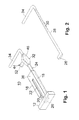
- a second embodiment 210 serving for understanding the present invention is shown in Figures 5 and 6.
- the base 212 has three leg portions 212a, 212b, and 212c, configured in a generally T-shaped pattern.
- the advantage of a T-shaped pattern is that it provides greater stability and maximum strength and support to the anti-theft device 210 when installed, in addition to reduced weight, in comparison to the solid rectangular base 12.
- the outboard ends of the leg portions 212a, 212b, 212c and the bottom of the first leg 216 suggestedly are beveled preferably at 45 degree angles, so that the pedal shaft 13 can more easily be guided into and out of the slot 22 when the device is installed and removed from the pedal shaft 13.
- the second embodiment 210 further incorporates an elongated cross member 236 for enabling the driver to press the device into the floorboard or carpet of the vehicle.
- the elongated cross member 236 extends horizontally from the top of the first leg 216, thus providing a sufficient surface area 238 for the foot of an operator to press downward. It is contemplated that the surface area 238 could include a gripping top surface.
- the second embodiment 210 further incorporates studs 240 which extend downward from the base 212 and which facilitate the positioning and retention of the device 210 against a floor particularly a carpeted floor 235 in the vehicle.
- the studs 240 prevent the device 210 from moving with respect to the floor.
- a device 110 may also incorporate cleats 142 which are cut into or otherwise provided in the bottom of the base 12. It is contemplated that a combination of studs 240 and cleats 142 could be used without departing from the scope and spirit of the invention.
- Lock housing 246 is smaller than housing 46 and hangs the lock cylinder across rod 28.
- the driver or operator desiring to utilize the device 10 unlocks the device and lowers the pin 26 all the way down to the base 12 (112, 212) by grasping the handle 34 and pushing the handle 34 toward the base 12 (112, 212).
- the base 12 (112, 212) is then placed on the floor 35 beneath the pedal shaft 13 which is located generally beneath the steering wheel and steering column (neither shown in Figs. 1-6).
- the pedal shaft 13, is then passed through the opening 20 in the U-shaped housing 14 (214) and into the slot 22 with the base 12 (112, 212) positioned squarely on the floor 35 of the vehicle.
- Figures 8-8B illustrates a third embodiment device 310 helping in understanding the present invention.
- the first and second legs 316, 318 are of substantially equal height and thus eliminate the need for a base as shown and described with respect to the first and second preferred embodiments.
- the first and second legs 316, 318 are spaced at the bottom to form an opening 320 which is tapered to slide over the pedal shaft 13, permitting the pedal shaft 13 to enter the slot 322, which begins at the narrow end of opening 320.
- the locking pin 326 is pulled upward by rod 328 thereby locking the pedal 11 and shaft 13 in an upward position as in the other embodiments described herein.
- the third preferred embodiment 310 further includes two rotatable feet 342, which are attached to the bottom of the first and second legs 316, 318 and which facilitate the pivotable support and positioning of the device 310.
- the main attribute of this embodiment is to facilitate ease of placement of the device 310.
- the locking mechanism 432 of the fourth preferred embodiment includes a locking pin 426 and a lock 444.
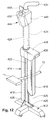
- the locking pin 426 is at one end of an elongated rod or shaft 428 (see Fig. 15) movable through the second leg 418 of the U-shaped housing 414 and the cylindrical housing 24.
- the locking pin 426 is selectively movable on the U-shaped housing 414 between a raised position shown in Fig. 13 and a retracted position shown in Fig. 12.
- the locking pin 426 In the raised position, the locking pin 426 is sufficiently close to a lower side of the pedal shaft 13 to prevent the pedal shaft 13 from being operably depressed, that is depressed sufficiently to enable the vehicle to be started and/or normally controlled. In the retracted position, the locking pin 426 permits travel of the pedal shaft 13 through the slot 22 and opening 20.
- the locking pin 426 of the fourth preferred embodiment 410 embodies a significant improvement over the designs of the first through third embodiments in that the upper, pedal shaft contacting surface 426a of the locking pin 426 is generally flat in a direction facing the pedal shaft 13. By providing a flattened shaft contact surface 426a, a larger contact region between the locking pin 426 and the pedal shaft 13 is created, thereby resulting in a more secure installation of the anti-theft device 410.
- a handle 434 On the opposing end of the rod 428 from the locking pin 426 is a handle 434, which differs from previous handles 34, 234, 334 of the first through third embodiments in several ways.
- the handle 434 is preferably threaded onto the rod 428. This is an improvement in security over prior designs, like embodiment 10, where an adhesive method of securing a smooth bored handle 34 to the end of a smooth rod 28 was employed. It is also contemplated that the handle 434 could be further attached to the rod 428 by welding, brazing, or the like, such that a secure, unitary structure is created preventing the unthreading of the handle 434 from rod 428.
- the handle 434 is attached to the rod 428 at a non-perpendicular angle to the rod 428.
- the upper surface of handle 434 is smoothly curved and extends away from the base 414 in a generally convex shape to further deflect impacts from directly above the rod 428.
- the handle 434 is made in one smooth piece without seams and with a smoothly varying, creaseless. seamless outer surface above rod 428, which does not have any edges to be engaged by a tool (e.g. chisel, saw or drill).
- Lock 444 is integrated into and is coupled to the U-shaped housing 414 through cylindrical tube 424.
- Lock 444 includes a cylinder 452 with the operative mechanical components in a housing or head.
- the lock 444 is operatively connected to the locking pin 426 to fix the locking pin 426 in at least the raised position through engagement of the lock 444 and the serrations 30 of the rod 428.
- the lock 444 has an upper face 450 with a key opening 454.
- the lock 444 is preferably a barrel type with a circular key opening 454 accepting a cylindrically shaped, barrel-type key 458 for greatly increased security in comparison to standard blank-type (flat) keys (not shown). Barrel-type key locks are particularly resistant to being picked and to being broken with slide hammers.
- a sheet metal screw attachment is commonly fitted to the end of a slide hammer and is easily screwed into locks that accept blank-type (flat) keys.
- the slide hammer is then used to pull the lock cylinder from its housing, thus defeating the security device. It is much more difficult for one to use this technique to defeat a lock having a circular key opening 454 and barrel-type key 458 as the sheet-metal screw attachment cannot readily be attached to such a lock.
- Lock housing 446 extends from the top of cylindrical member 424 in the direction of base leg portion 412c towards the operator seated in front of the device 410.
- the upper face 450 of the lock 444 and lock cylinder 452 faces substantially oppositely away from the base 412.
- the upper face 450 is pitched at an angle which is transverse (i.e. non-perpendicular and non-parallel) to a support plane defined by the bottom of the base 412 (or more particularly, the bottoms of stud 440 and cleats 442).
- the face is pitched downwardly from the plane of the base suggestedly at an angle of between about 15 and 30 degrees, more particularly between about 20 and 25 degrees.
- Orientation of the upper face 450, and hence the cylinder 452 in a direction substantially oppositely away from the base 412 obviates problems encountered with previous locking anti-theft mechanisms where the locks faced in a lateral direction (i.e., the first three embodiments).
- the lock faced leftwardly and the operator was right handed the operator had to use his or her off-hand to operate the lock to fix the anti-theft device.
- the orientation of the upper face 450 of the lock 444 of the preferred embodiment 410 solves this problem by enabling the operator to use his or her dominant hand to fix the device 410 to the vehicle.
- orientation of the upper face 450 in a direction substantially oppositely away from the base 412 provides additional security with respect to cutting through the lock housing 446 with a saw.
- the lock housing 46 positioned the lock cylinder 52 in a direction perpendicular to the rod 28
- the side of the lock housing 46 surrounding the lock cylinder 52 could readily be engaged by a hacksaw, thereby permitting one to cut through the lock 44 to defeat the device 10.
- Directing the upper face 450 oppositely away from the base 412 eliminates any substantial upper surface to which one can engage a hacksaw and further serves to deflect blows delivered from above the device 410.
- the lock cylinder 452 is protected by the lock housing 446, which surrounds the lock cylinder 452.
- the lock housing 446 preferably has more than four lateral sides. For example, eight lateral sides are depicted forming the perimeter of the upper face 450 in Fig. 9. Only the side 438a closest to rod 28 (Fig. 11) is rectangular. The remaining seven lateral sides surrounding upper face 450 are triangular or trapezoidal. The only other rectangular lateral side is side 438b (also Fig. 11).
- By providing more than four lateral sides 448, and particularly non-rectangular sides one is presented with great difficulty in perpendicularly engaging the intersection of the upper face 450 and the lateral sides 448 or any of the lateral sides 448 directly with a hacksaw. A perpendicular engagement between a hacksaw blade (not shown) and the surface intended to be cut is optimal for efficient cutting.
- lock 444 includes a separate latch member in housing 446 which engages the serrations 30 of the rod 428 to secure the rod 428 and locking pin 426.
- the latch preferably is spring loaded into engagement with the serrations and is disengaged only by rotation of the inner member of the cylinder 452 turned by key 458.
- the latch is not part of the cylinder but the cylinder 452 is need to disengage the latch. Therefore, destruction of the cylinder 452, for example by drilling it out, will not release the latch.
- the internal latch is further protected from attempting to freeze the cylinder to shrink it.
- the lock housing 446 is made from a tough material to prevent the lock 444 from readily being defeated by cutting or impact, preferably hardened steel.
- the legs 416, 418 and cross member 436 of the generally U-shaped housing 414 and cylindrical tube 424 of the preferred embodiment device 410 are also made from similarly tough material, preferably hardened steel. While it is contemplated that other tough metals (e.g., stainless steel) could be employed without departing from the scope and spirit of the invention, hardened steel provides an optimal balance between high strength and thus security and expense.
- first leg 416 and second leg 418 of the U-shaped housing 414 are connected by cross member 436.
- the cross member 436 overlaps each of the first and second legs 416, 418 and presents lower edges 437 of the cross member 436 overlapping the legs 416, 418 and which are welded to the upper sides of the first and second legs 416, 418 by welds 460 best seen in Figs. 9-11.
- rigidity of the first and second legs 416, 418 and the U-shaped housing 414 is increased. Accordingly, security of the anti-theft device 410 is greatly increased. As shown in Figs.
- cross member 436 be welded at 460' to the first leg 416 along the horizontal and two vertical interior intersections of those two members to further increase structural integrity of the anti-theft device 410 and prevent the removal of the first leg 416 from the housing 414.
- Cross member 436 preferably extends fully across second leg 418 and rod 428 is passed through the cross member 436 to deter disassembly of housing 414.
- first leg 416 is a generally U-shaped member (when viewed in axial cross section) with opposing parallel arms 416a, 416b joined by a cross wall 416c.
- the cross wall 416c has a deflection, preferably an outward bow 416d between the pair of arms 416a, 416b, for increased longitudinal stiffness of the leg 416 (and/or 418) with respect to ordinary channel stock.
- first and second legs 416, 418 Forming at least one of the first and second legs 416, 418 as a generally U-shaped member like member 416 with bowed or otherwise stiffened cross wall overcomes a significant drawback of prior designs that employed simple channel stock of three straight, perpendicular walls to form the first and second legs 16, 18.
- the longitudinal stiffness of straight-sided channel stock is significantly lower than that of the U-shaped configuration with a deflected cross wall 416c. It is correspondingly easier to defeat a security device having first and second legs 16, 18 made from simple channel stock simply by bending the first leg 16 such that the pedal shaft 13 can be removed from the slot 22 between the pin 26 and the bent leg 16.
- leg 416 and of the walls 416a, 416b and/or 416c in particular could be used to form the first or first and second legs 416, 418 for increased strength without departing from the scope of the present invention as defined by the claims.
- Fig. 15 depicts rod 428 with serrations 30, locking pin 426 and handle 434.
- the rod 428 and pin 426 are formed from a single piece of hardened steel.
- handle 434 is separately formed from a single piece of tough material, preferably forges from hardened steel, and threaded onto rod 428.
- the anti-theft device 410 can be combined with a banner configured for attachment to the vehicle to announce the use of the device.
- the banner 62 preferably is a cover configured for attachment to the steering wheel 64 of the vehicle.
- the banner 62 preferably has a logo 64 or other identifying indicia to inform would-be thieves that the vehicle is immobilized through use of the anti-theft device 10, 210, 310, 410.
- the banner need not be attached to the steering wheel 64 of the vehicle, but can be configured to be mounted in any visible location, such as on the interior surface of the windshield 68 or another window, on the dashboard 70, or hanging from a rearview mirror 72.
- the banner 62 may include a legend 66 announcing that the vehicle is protected, preferably including the word "PROTECTED” or a word of similar impact and meaning.
- the device of the present invention may include a protective outer coating composed of vinyl, PTFE, rubber or plastic.
Abstract
Description
Claims (13)
- A device (410, 510) to lock a brake or clutch pedal of a vehicle so as to deter theft of the vehicle, the device comprising:characterised in that the lock (444) has an upper face (450) with a key opening (454), whereby the upper face faces substantially oppositely away from the base (412).a base (412) for placement on the floor of the vehicle beneath the pedal (11) of the vehicle and a pedal shaft (13) supporting the pedal;a generally U-shaped housing (414) having a second leg (418) attached to the base member, a first leg (416) shorter than the second leg, and a cross member (436) connecting the first and second legs to define an opening (420) between the first leg (416) and the base (412) and a slot (422) between the first and second legs (416, 418), the opening (420) and slot (422) being sufficiently large to receive the pedal shaft (13) and permit travel of the pedal shaft through the slot;a locking pin (426) selectively movable on the U-shaped housing (414) between a raised position sufficiently close to a lower side of the pedal shaft to prevent the pedal shaft from being depressed sufficiently to enable the vehicle to be started and a retracted position to permit travel of the pedal shaft through the slot and opening; anda lock (444) coupled to the U-shaped housing (414) and operably connected to the locking pin (426) to fix the locking pin in at least the raised position,
- The device according to claim 1 wherein the base (412) defines a support plane and the upper face (450) is pitched at a transverse, non-perpendicular angle to the support plane.
- The device according to claim 1 wherein the key opening (454) is circular.
- The device according to claim 1 wherein the lock (444) is protected by a lock housing (446) having more than four lateral sides extending from the upper face (450).
- The device according to claim 4 wherein at least the lock housing (446) is formed from hardened or stainless steel.
- The device according to claim 1 wherein at least the U-shaped housing (414) is formed from a plurality of hardened or stainless steel members welded together.
- The device according to claim 1 wherein the locking pin (426) has a generally flat surface (426a) facing away from the base (412).
- The device according to claim 1 wherein at least one of the first and second legs (416, 418) is a generally U-shaped member with a pair of opposing parallel arms (416a, 416b) joined by a cross wall (416c) and wherein the cross wall has a deflection (416d) between the pair of arms for increased longitudinal stiffness.
- The device according to claim 1 wherein the locking pin (426) is fixed at one end of an elongated rod (28, 428) movable through the second leg (416) of the U-shaped housing (414) and further comprising a handle (434) on an opposing end of the rod extending transversely to one side of the rod at a non-perpendicular angle to the rod.
- The device according to claim 9 wherein the handle (434) is made in one piece and has a curving, creaseless, seamless outer surface beyond the rod.
- The device according to claim 10 wherein the handle (434) has an upper surface smoothly curving away from the base (412) in a generally convex shape.
- The device according to claim 1 further in combination with a banner (62) configured for attachment to the vehicle to indicate the presence of the device.
- A vehicle comprising the device according to claim 12 wherein the vehicle also includes a steering wheel (64) above the pedal (11) and wherein the banner (62) comprises a cover configured for attachment to the steering wheel.
Applications Claiming Priority (5)
| Application Number | Priority Date | Filing Date | Title |
|---|---|---|---|
| US268803 | 1994-06-29 | ||
| US09/268,803 US6089055A (en) | 1997-10-10 | 1999-03-16 | Anti-theft brake or clutch locking device |
| US09/495,098 US6192724B1 (en) | 1997-10-10 | 2000-02-01 | Anti-theft brake or clutch pedal locking device |
| US495098 | 2000-02-01 | ||
| PCT/US2000/006923 WO2000055525A1 (en) | 1999-03-16 | 2000-03-16 | Anti-theft brake or clutch pedal locking device |
Publications (3)
| Publication Number | Publication Date |
|---|---|
| EP1159550A1 EP1159550A1 (en) | 2001-12-05 |
| EP1159550A4 EP1159550A4 (en) | 2002-11-06 |
| EP1159550B1 true EP1159550B1 (en) | 2004-02-25 |
Family
ID=26953334
Family Applications (1)
| Application Number | Title | Priority Date | Filing Date |
|---|---|---|---|
| EP00916406A Expired - Lifetime EP1159550B1 (en) | 1999-03-16 | 2000-03-16 | Anti-theft brake or clutch pedal locking device |
Country Status (14)
| Country | Link |
|---|---|
| US (3) | US6192724B1 (en) |
| EP (1) | EP1159550B1 (en) |
| JP (1) | JP4560214B2 (en) |
| KR (1) | KR20020010124A (en) |
| CN (1) | CN1149159C (en) |
| AT (1) | ATE260426T1 (en) |
| AU (1) | AU751691B2 (en) |
| BR (1) | BR0009036A (en) |
| CA (1) | CA2368128A1 (en) |
| DE (1) | DE60008505D1 (en) |
| IL (1) | IL145101A0 (en) |
| MX (1) | MXPA01009421A (en) |
| NZ (1) | NZ513756A (en) |
| WO (1) | WO2000055525A1 (en) |
Families Citing this family (31)
| Publication number | Priority date | Publication date | Assignee | Title |
|---|---|---|---|---|
| US5870912A (en) | 1997-10-10 | 1999-02-16 | Lawman Armor Corporation | Anti-theft brake locking device |
| US5881587A (en) | 1997-10-10 | 1999-03-16 | Lawman Armor Corp. | Anti-theft brake or clutch locking device |
| US6192724B1 (en) * | 1997-10-10 | 2001-02-27 | Robert A. Vito | Anti-theft brake or clutch pedal locking device |
| TW522944U (en) * | 2001-03-13 | 2003-03-01 | Chan Hau Entpr Co Ltd | Lock for vehicle |
| US6662894B2 (en) | 2001-06-15 | 2003-12-16 | Watchara Chantrasuwan | Automotive brake/clutch lock |
| US6679089B2 (en) | 2001-10-19 | 2004-01-20 | Robert A. Vito | Type of automobile anti-theft device |
| US6460385B1 (en) | 2001-12-07 | 2002-10-08 | Robert A. Vito | Column lock device |
| US6516642B1 (en) | 2001-12-07 | 2003-02-11 | Robert A. Vito | Column security device |
| US6792780B1 (en) * | 2002-06-25 | 2004-09-21 | Achille A. De Lucia | Universal portable brake pedal locking device for vehicles |
| US6666052B1 (en) * | 2002-09-12 | 2003-12-23 | Chia-Lin Chen | Automobile pedal lockset with vertical entry |
| US20040261476A1 (en) * | 2003-06-26 | 2004-12-30 | Dix Victor George | Big-Un vehicle security device |
| DE102004042417B3 (en) * | 2004-09-02 | 2006-01-05 | Bayerische Motoren Werke Ag | Method for emergency disabling an automatic transmission |
| US6976374B1 (en) * | 2005-01-25 | 2005-12-20 | Christopher Dougherty | Vehicle pedal lock |
| JP4625724B2 (en) * | 2005-06-28 | 2011-02-02 | 株式会社ホンダロック | Vehicle anti-theft device |
| US20080148792A1 (en) * | 2006-12-12 | 2008-06-26 | Ross Davis | Automobile steering wheel and brake pedal locking device |
| WO2011087463A2 (en) * | 2010-01-14 | 2011-07-21 | Kamol Kantajaraniti | Brake/clutch locking device having anti-lock mechanism |
| US20110242587A1 (en) * | 2010-04-05 | 2011-10-06 | Kabushiki Kaisha Toshiba | Image forming device system, printing selection device, print server, image forming device and selection method thereof |
| CN102213042A (en) * | 2010-04-08 | 2011-10-12 | 黄法静 | Vehicle anti-theft lock |
| US8607602B1 (en) * | 2010-09-09 | 2013-12-17 | Godwin Okoye | Passenger portable safety brake |
| CN102910154A (en) * | 2012-02-27 | 2013-02-06 | 付长发 | Antitheft-lock-type fully closed antitheft hand brake |
| MY152210A (en) * | 2012-07-17 | 2014-08-29 | Ng Chee Wah | Anti-theft device |
| CN103129518B (en) * | 2013-01-14 | 2016-06-22 | 苏梅 | The supporting construction of pedal lock |
| CN103129517B (en) * | 2013-01-31 | 2016-08-24 | 李吉源 | The connecting structure of pedal lock |
| CN103273904B (en) * | 2013-04-17 | 2016-08-10 | 苏梅 | Safe self-saving type automobile lock |
| DE102015201540B4 (en) * | 2014-03-07 | 2018-05-30 | Volkswagen Aktiengesellschaft | Method and device for operating a vehicle with an automatic driving mode |
| CN104210459B (en) * | 2014-08-20 | 2016-08-10 | 林嘉伟 | A kind of double structure mechanical automobile theft preventing method and burglary-resisting system thereof |
| USD813646S1 (en) * | 2016-07-24 | 2018-03-27 | Michael Krall | Gate lock |
| KR101935910B1 (en) | 2017-12-29 | 2019-01-07 | 주식회사 유라코퍼레이션 | Device and method for locking accelerator pedal |
| USD926548S1 (en) | 2019-06-28 | 2021-08-03 | Mike Gordon | Locking boot for vehicle wheel |
| USD906080S1 (en) * | 2019-06-28 | 2020-12-29 | Mike Gordon | Locking boot for vehicle wheel |
| US10596996B1 (en) * | 2019-10-30 | 2020-03-24 | Ramon Ruben Lopez | Vehicle brake pedal lock |
Family Cites Families (49)
| Publication number | Priority date | Publication date | Assignee | Title |
|---|---|---|---|---|
| GB160160A (en) | 1920-03-12 | 1921-12-29 | Joseph Maceska | Improvements in and relating to automobile locks |
| FR862868A (en) | 1939-01-12 | 1941-03-18 | Auto theft security device | |
| US2330536A (en) | 1941-06-16 | 1943-09-28 | Maximilian E Zimmermann | Means for locking vehicles against self-propulsion |
| US2744409A (en) | 1953-09-14 | 1956-05-08 | Jr Harry D Wintle | Electromagnetic dynamometer |
| US3245239A (en) | 1962-12-27 | 1966-04-12 | Zaidener Kitty | Anti-theet device for road vehicles |
| GB1033994A (en) * | 1964-04-18 | 1966-06-22 | Nuneaton Engineering Company L | Ground-engaging support for a post |
| US3889499A (en) | 1974-11-01 | 1975-06-17 | William H Cramer | Automobile accelerator locking device |
| US4040675A (en) | 1976-07-26 | 1977-08-09 | Raymond Richmond | Anti-theft vehicle brake-supervising device |
| FR2419846A1 (en) | 1978-03-15 | 1979-10-12 | Garces Guy | Antitheft device for car - has two box-like parts, one housing clutch pedal and one lock for locking rod |
| FR2422529A1 (en) | 1978-04-13 | 1979-11-09 | Leclert Bernard Raymond | Antitheft device for vehicles - immobilises clutch pedal in either high or low position |
| GB2023520A (en) | 1978-04-25 | 1980-01-03 | Stoodley J | Vehicle Anti-Theft Locking Arrangement |
| FR2443946A1 (en) | 1978-12-15 | 1980-07-11 | Sourbe Jean Pierre | Compact anti-theft vehicle clamp - locks clutch and brake pedal levers together against chassis floor |
| GB2091656A (en) | 1981-01-24 | 1982-08-04 | Cowie David Black | Vehicle anti-theft device |
| US4471852A (en) | 1982-02-08 | 1984-09-18 | Ike Schield | Anti-theft devices for automotive vehicles |
| US4493198A (en) | 1982-09-03 | 1985-01-15 | Brown William B | Anti-theft lock for pedal operated apparatus |
| FR2579943A1 (en) | 1985-04-04 | 1986-10-10 | Mazeirat Jean | Anti-theft device for motor vehicles, acting by locking the control pedals |
| FR2580243A1 (en) * | 1985-04-10 | 1986-10-17 | Desfarges Serge | Anti-theft safety device for a motor vehicle |
| US4779435A (en) | 1985-09-04 | 1988-10-25 | Farrow Robert T | Anti-theft device for road vehicles |
| ATE58879T1 (en) | 1985-11-26 | 1990-12-15 | Winner James | STEERING WHEEL LOCK FOR MOTOR VEHICLES. |
| IT1224564B (en) | 1988-11-15 | 1990-10-04 | Riccitelli Guglielmo | FOR VEHICLES WITH AUTOMATIC TRANSMISSION ANTI-THEFT DEVICE LOCK-PEDALS FOR VEHICLES, IN PARTICULAR SUITABLE |
| US4934492A (en) | 1989-04-10 | 1990-06-19 | Hayes Sheen Michael P | Automatic vehicle brake lock system |
| ES2014149A6 (en) | 1989-06-19 | 1990-06-16 | Gusine Juan Orpi | Anti-theft bar for motor vehicles. |
| AU609372B3 (en) * | 1990-07-20 | 1991-03-06 | Ching-Rong Wang | Automobile steering lock with a rod anti-releasing mechanism |
| US5040387A (en) | 1990-10-18 | 1991-08-20 | Knott Lock Corporation | Vehicle brake lock assembly |
| GB9109139D0 (en) | 1991-04-27 | 1991-06-12 | Hellewell M R | Lock fast |
| FR2681823A1 (en) | 1991-09-26 | 1993-04-02 | Bosch Jose | Antitheft device for motor vehicles |
| DE9215118U1 (en) | 1992-11-06 | 1992-12-17 | Link, Wolfgang, 7401 Pliezhausen, De | |
| US5267458A (en) | 1992-12-28 | 1993-12-07 | Heh Mao Lin | Car lock multiple locking purposes |
| CA2152933A1 (en) | 1992-12-30 | 1994-07-21 | Larry Charles Hinnergardt | Treatment of fruits and vegetables by calcium salts |
| US5345796A (en) | 1993-03-08 | 1994-09-13 | Chieh Peter T C | Vehicle brake-pedal locking device |
| US5354031A (en) * | 1993-03-29 | 1994-10-11 | Dayva International, Inc. | Low-profile umbrella base |
| US5537846A (en) | 1993-08-26 | 1996-07-23 | Simon; David A. | Control pedal disabling device |
| FR2719005B1 (en) | 1994-04-25 | 1996-09-20 | Alfredo Mellini | Auto mechanical anti-theft device blocking the brake and clutch pedals. |
| IT1277849B1 (en) | 1994-09-19 | 1997-11-12 | Guglielmo Riccitelli | ANTI-THEFT FOR LOCKING THE STEERING WHEEL OF ANY KIND OF VEHICLE. |
| US5653133A (en) | 1995-10-16 | 1997-08-05 | Passantino; Frank | Steering wheel and brake locking device for road vehicles |
| FR2744409B1 (en) | 1996-02-07 | 1998-04-24 | Mellini Alfredo | ANTI-THEFT DEVICE FOR VEHICLES, FOR LOCKING AT LEAST ONE PEDAL |
| US5979197A (en) * | 1995-10-24 | 1999-11-09 | Mellini; Alfredo | Vehicle anti-theft device for blocking at least a pedal arm |
| US5704233A (en) | 1996-05-06 | 1998-01-06 | Farshad; Fred F. | Anti-theft device for vehicles |
| US5906121A (en) * | 1996-08-29 | 1999-05-25 | Mankarious; Adel H. | Pedal lock anti-theft apparatus for vehicles |
| US5715710A (en) | 1996-11-22 | 1998-02-10 | De Lucia; Achille A. | Portable anti-theft device for motor vehicle |
| US5950463A (en) * | 1997-02-12 | 1999-09-14 | Glazier; James | Vehicle brake locking apparatus |
| US5778706A (en) | 1997-06-27 | 1998-07-14 | Testa; Troy | Marine propeller anti-theft device |
| US5881587A (en) * | 1997-10-10 | 1999-03-16 | Lawman Armor Corp. | Anti-theft brake or clutch locking device |
| US6089055A (en) | 1997-10-10 | 2000-07-18 | Vito; Robert A. | Anti-theft brake or clutch locking device |
| US5870912A (en) * | 1997-10-10 | 1999-02-16 | Lawman Armor Corporation | Anti-theft brake locking device |
| US6192724B1 (en) * | 1997-10-10 | 2001-02-27 | Robert A. Vito | Anti-theft brake or clutch pedal locking device |
| DE29719904U1 (en) * | 1997-11-08 | 1998-02-12 | Bilgery Gmbh | Umbrella base |
| US5911765A (en) * | 1997-12-03 | 1999-06-15 | Scott D. Jacobson | Control pedal disabling device |
| US6202456B1 (en) * | 2000-02-18 | 2001-03-20 | Winner International Royalty Llc | Anti-theft device for vehicles |
-
2000
- 2000-02-01 US US09/495,098 patent/US6192724B1/en not_active Expired - Fee Related
- 2000-03-16 AT AT00916406T patent/ATE260426T1/en not_active IP Right Cessation
- 2000-03-16 BR BR0009036A patent/BR0009036A/en not_active Application Discontinuation
- 2000-03-16 KR KR1020017011692A patent/KR20020010124A/en not_active Application Discontinuation
- 2000-03-16 JP JP2000605118A patent/JP4560214B2/en not_active Expired - Fee Related
- 2000-03-16 MX MXPA01009421A patent/MXPA01009421A/en active IP Right Grant
- 2000-03-16 NZ NZ513756A patent/NZ513756A/en not_active Application Discontinuation
- 2000-03-16 CA CA002368128A patent/CA2368128A1/en not_active Abandoned
- 2000-03-16 DE DE60008505T patent/DE60008505D1/en not_active Expired - Lifetime
- 2000-03-16 IL IL14510100A patent/IL145101A0/en unknown
- 2000-03-16 AU AU37514/00A patent/AU751691B2/en not_active Ceased
- 2000-03-16 CN CNB008044465A patent/CN1149159C/en not_active Expired - Fee Related
- 2000-03-16 EP EP00916406A patent/EP1159550B1/en not_active Expired - Lifetime
- 2000-03-16 WO PCT/US2000/006923 patent/WO2000055525A1/en not_active Application Discontinuation
-
2001
- 2001-01-29 US US09/772,181 patent/US6298696B2/en not_active Expired - Lifetime
- 2001-10-05 US US09/971,729 patent/US6463772B2/en not_active Expired - Lifetime
Also Published As
| Publication number | Publication date |
|---|---|
| US6298696B2 (en) | 2001-10-09 |
| DE60008505D1 (en) | 2004-04-01 |
| EP1159550A4 (en) | 2002-11-06 |
| WO2000055525A1 (en) | 2000-09-21 |
| US6463772B2 (en) | 2002-10-15 |
| ATE260426T1 (en) | 2004-03-15 |
| US20010002543A1 (en) | 2001-06-07 |
| IL145101A0 (en) | 2002-06-30 |
| US6192724B1 (en) | 2001-02-27 |
| EP1159550A1 (en) | 2001-12-05 |
| CN1354825A (en) | 2002-06-19 |
| NZ513756A (en) | 2003-05-30 |
| AU751691B2 (en) | 2002-08-22 |
| JP2002539025A (en) | 2002-11-19 |
| MXPA01009421A (en) | 2003-06-06 |
| AU3751400A (en) | 2000-10-04 |
| US20020014097A1 (en) | 2002-02-07 |
| CN1149159C (en) | 2004-05-12 |
| JP4560214B2 (en) | 2010-10-13 |
| CA2368128A1 (en) | 2000-09-21 |
| BR0009036A (en) | 2001-12-18 |
| KR20020010124A (en) | 2002-02-02 |
Similar Documents
| Publication | Publication Date | Title |
|---|---|---|
| EP1159550B1 (en) | Anti-theft brake or clutch pedal locking device | |
| EP1021663B1 (en) | Anti-theft brake or clutch locking device | |
| USRE39248E1 (en) | Anti-theft brake locking device | |
| US4825670A (en) | Vehicle shift and radio security lock device | |
| US6089055A (en) | Anti-theft brake or clutch locking device | |
| US5644937A (en) | Vehicle theft prevention device | |
| US20010005997A1 (en) | Anti-theft brake or clutch pedal locking device | |
| US20030115916A1 (en) | Anti-theft brake or clutch pedal locking device | |
| US4972693A (en) | Vehicle anti-theft device | |
| US6109076A (en) | Automobile and airbag anti-theft device | |
| US5442942A (en) | Automotive anti-theft protection apparatus | |
| US5689983A (en) | Ignition rack and sector gear for a steering column | |
| EP0656843B1 (en) | A device for preventing car thefts | |
| JP2595547Y2 (en) | Bracket for steering column support | |
| WO2012050430A1 (en) | An apparatus for securing a pedal of a vehicle | |
| GB2134463A (en) | Security device | |
| GB2300606A (en) | A safety steering wheel | |
| DK9300024U3 (en) | Device for car theft protection | |
| MXPA00003473A (en) | Anti-theft brake or clutch locking device | |
| JPH09240533A (en) | Antitheft device for bicycle |
Legal Events
| Date | Code | Title | Description |
|---|---|---|---|
| PUAI | Public reference made under article 153(3) epc to a published international application that has entered the european phase |
Free format text: ORIGINAL CODE: 0009012 |
|
| 17P | Request for examination filed |
Effective date: 20010919 |
|
| AK | Designated contracting states |
Kind code of ref document: A1 Designated state(s): AT BE CH CY DE DK ES FI FR GB GR IE IT LI LU MC NL PT SE |
|
| AX | Request for extension of the european patent |
Free format text: AL;LT;LV;MK;RO;SI |
|
| A4 | Supplementary search report drawn up and despatched |
Effective date: 20020919 |
|
| AK | Designated contracting states |
Kind code of ref document: A4 Designated state(s): AT BE CH CY DE DK ES FI FR GB GR IE IT LI LU MC NL PT SE |
|
| 17Q | First examination report despatched |
Effective date: 20021210 |
|
| GRAP | Despatch of communication of intention to grant a patent |
Free format text: ORIGINAL CODE: EPIDOSNIGR1 |
|
| RIC1 | Information provided on ipc code assigned before grant |
Ipc: 7F 16H 57/00 A Ipc: 7B 60R 25/00 B |
|
| GRAS | Grant fee paid |
Free format text: ORIGINAL CODE: EPIDOSNIGR3 |
|
| GRAA | (expected) grant |
Free format text: ORIGINAL CODE: 0009210 |
|
| AK | Designated contracting states |
Kind code of ref document: B1 Designated state(s): AT BE CH CY DE DK ES FI FR GB GR IE IT LI LU MC NL PT SE |
|
| PG25 | Lapsed in a contracting state [announced via postgrant information from national office to epo] |
Ref country code: IT Free format text: LAPSE BECAUSE OF FAILURE TO SUBMIT A TRANSLATION OF THE DESCRIPTION OR TO PAY THE FEE WITHIN THE PRESCRIBED TIME-LIMIT;WARNING: LAPSES OF ITALIAN PATENTS WITH EFFECTIVE DATE BEFORE 2007 MAY HAVE OCCURRED AT ANY TIME BEFORE 2007. THE CORRECT EFFECTIVE DATE MAY BE DIFFERENT FROM THE ONE RECORDED. Effective date: 20040225 Ref country code: CY Free format text: LAPSE BECAUSE OF FAILURE TO SUBMIT A TRANSLATION OF THE DESCRIPTION OR TO PAY THE FEE WITHIN THE PRESCRIBED TIME-LIMIT Effective date: 20040225 Ref country code: AT Free format text: LAPSE BECAUSE OF FAILURE TO SUBMIT A TRANSLATION OF THE DESCRIPTION OR TO PAY THE FEE WITHIN THE PRESCRIBED TIME-LIMIT Effective date: 20040225 Ref country code: FI Free format text: LAPSE BECAUSE OF FAILURE TO SUBMIT A TRANSLATION OF THE DESCRIPTION OR TO PAY THE FEE WITHIN THE PRESCRIBED TIME-LIMIT Effective date: 20040225 Ref country code: FR Free format text: LAPSE BECAUSE OF FAILURE TO SUBMIT A TRANSLATION OF THE DESCRIPTION OR TO PAY THE FEE WITHIN THE PRESCRIBED TIME-LIMIT Effective date: 20040225 Ref country code: NL Free format text: LAPSE BECAUSE OF FAILURE TO SUBMIT A TRANSLATION OF THE DESCRIPTION OR TO PAY THE FEE WITHIN THE PRESCRIBED TIME-LIMIT Effective date: 20040225 Ref country code: LI Free format text: LAPSE BECAUSE OF FAILURE TO SUBMIT A TRANSLATION OF THE DESCRIPTION OR TO PAY THE FEE WITHIN THE PRESCRIBED TIME-LIMIT Effective date: 20040225 Ref country code: ES Free format text: LAPSE BECAUSE OF FAILURE TO SUBMIT A TRANSLATION OF THE DESCRIPTION OR TO PAY THE FEE WITHIN THE PRESCRIBED TIME-LIMIT Effective date: 20040225 Ref country code: BE Free format text: LAPSE BECAUSE OF FAILURE TO SUBMIT A TRANSLATION OF THE DESCRIPTION OR TO PAY THE FEE WITHIN THE PRESCRIBED TIME-LIMIT Effective date: 20040225 Ref country code: CH Free format text: LAPSE BECAUSE OF FAILURE TO SUBMIT A TRANSLATION OF THE DESCRIPTION OR TO PAY THE FEE WITHIN THE PRESCRIBED TIME-LIMIT Effective date: 20040225 |
|
| REG | Reference to a national code |
Ref country code: GB Ref legal event code: FG4D |
|
| REG | Reference to a national code |
Ref country code: CH Ref legal event code: EP |
|
| PG25 | Lapsed in a contracting state [announced via postgrant information from national office to epo] |
Ref country code: LU Free format text: LAPSE BECAUSE OF NON-PAYMENT OF DUE FEES Effective date: 20040316 Ref country code: IE Free format text: LAPSE BECAUSE OF NON-PAYMENT OF DUE FEES Effective date: 20040316 |
|
| REG | Reference to a national code |
Ref country code: IE Ref legal event code: FG4D |
|
| PG25 | Lapsed in a contracting state [announced via postgrant information from national office to epo] |
Ref country code: MC Free format text: LAPSE BECAUSE OF NON-PAYMENT OF DUE FEES Effective date: 20040331 |
|
| REF | Corresponds to: |
Ref document number: 60008505 Country of ref document: DE Date of ref document: 20040401 Kind code of ref document: P |
|
| PG25 | Lapsed in a contracting state [announced via postgrant information from national office to epo] |
Ref country code: GR Free format text: LAPSE BECAUSE OF FAILURE TO SUBMIT A TRANSLATION OF THE DESCRIPTION OR TO PAY THE FEE WITHIN THE PRESCRIBED TIME-LIMIT Effective date: 20040525 Ref country code: SE Free format text: LAPSE BECAUSE OF FAILURE TO SUBMIT A TRANSLATION OF THE DESCRIPTION OR TO PAY THE FEE WITHIN THE PRESCRIBED TIME-LIMIT Effective date: 20040525 Ref country code: GB Free format text: LAPSE BECAUSE OF NON-PAYMENT OF DUE FEES Effective date: 20040525 Ref country code: DK Free format text: LAPSE BECAUSE OF FAILURE TO SUBMIT A TRANSLATION OF THE DESCRIPTION OR TO PAY THE FEE WITHIN THE PRESCRIBED TIME-LIMIT Effective date: 20040525 |
|
| PG25 | Lapsed in a contracting state [announced via postgrant information from national office to epo] |
Ref country code: DE Free format text: LAPSE BECAUSE OF FAILURE TO SUBMIT A TRANSLATION OF THE DESCRIPTION OR TO PAY THE FEE WITHIN THE PRESCRIBED TIME-LIMIT Effective date: 20040526 |
|
| NLV1 | Nl: lapsed or annulled due to failure to fulfill the requirements of art. 29p and 29m of the patents act | ||
| LTIE | Lt: invalidation of european patent or patent extension |
Effective date: 20040225 |
|
| REG | Reference to a national code |
Ref country code: CH Ref legal event code: PL |
|
| PLBE | No opposition filed within time limit |
Free format text: ORIGINAL CODE: 0009261 |
|
| STAA | Information on the status of an ep patent application or granted ep patent |
Free format text: STATUS: NO OPPOSITION FILED WITHIN TIME LIMIT |
|
| GBPC | Gb: european patent ceased through non-payment of renewal fee |
Effective date: 20040525 |
|
| REG | Reference to a national code |
Ref country code: IE Ref legal event code: MM4A |
|
| EN | Fr: translation not filed | ||
| 26N | No opposition filed |
Effective date: 20041126 |
|
| PG25 | Lapsed in a contracting state [announced via postgrant information from national office to epo] |
Ref country code: PT Free format text: LAPSE BECAUSE OF NON-PAYMENT OF DUE FEES Effective date: 20040725 |