EP1021663B1 - Anti-theft brake or clutch locking device - Google Patents
Anti-theft brake or clutch locking device Download PDFInfo
- Publication number
- EP1021663B1 EP1021663B1 EP98930282A EP98930282A EP1021663B1 EP 1021663 B1 EP1021663 B1 EP 1021663B1 EP 98930282 A EP98930282 A EP 98930282A EP 98930282 A EP98930282 A EP 98930282A EP 1021663 B1 EP1021663 B1 EP 1021663B1
- Authority
- EP
- European Patent Office
- Prior art keywords
- ins
- insert
- date
- del
- delete
- Prior art date
- Legal status (The legal status is an assumption and is not a legal conclusion. Google has not performed a legal analysis and makes no representation as to the accuracy of the status listed.)
- Expired - Lifetime
Links
Images
Classifications
-
- B—PERFORMING OPERATIONS; TRANSPORTING
- B60—VEHICLES IN GENERAL
- B60R—VEHICLES, VEHICLE FITTINGS, OR VEHICLE PARTS, NOT OTHERWISE PROVIDED FOR
- B60R25/00—Fittings or systems for preventing or indicating unauthorised use or theft of vehicles
- B60R25/01—Fittings or systems for preventing or indicating unauthorised use or theft of vehicles operating on vehicle systems or fittings, e.g. on doors, seats or windscreens
-
- B—PERFORMING OPERATIONS; TRANSPORTING
- B60—VEHICLES IN GENERAL
- B60R—VEHICLES, VEHICLE FITTINGS, OR VEHICLE PARTS, NOT OTHERWISE PROVIDED FOR
- B60R25/00—Fittings or systems for preventing or indicating unauthorised use or theft of vehicles
- B60R25/002—Locking of control actuating or transmitting means
- B60R25/003—Locking of control actuating or transmitting means locking of control actuating means
- B60R25/005—Locking of control actuating or transmitting means locking of control actuating means of foot actuated control means
-
- Y—GENERAL TAGGING OF NEW TECHNOLOGICAL DEVELOPMENTS; GENERAL TAGGING OF CROSS-SECTIONAL TECHNOLOGIES SPANNING OVER SEVERAL SECTIONS OF THE IPC; TECHNICAL SUBJECTS COVERED BY FORMER USPC CROSS-REFERENCE ART COLLECTIONS [XRACs] AND DIGESTS
- Y10—TECHNICAL SUBJECTS COVERED BY FORMER USPC
- Y10T—TECHNICAL SUBJECTS COVERED BY FORMER US CLASSIFICATION
- Y10T70/00—Locks
- Y10T70/50—Special application
- Y10T70/5611—For control and machine elements
- Y10T70/569—Lever
- Y10T70/573—Single
- Y10T70/5735—Externally mounted locking device
-
- Y—GENERAL TAGGING OF NEW TECHNOLOGICAL DEVELOPMENTS; GENERAL TAGGING OF CROSS-SECTIONAL TECHNOLOGIES SPANNING OVER SEVERAL SECTIONS OF THE IPC; TECHNICAL SUBJECTS COVERED BY FORMER USPC CROSS-REFERENCE ART COLLECTIONS [XRACs] AND DIGESTS
- Y10—TECHNICAL SUBJECTS COVERED BY FORMER USPC
- Y10T—TECHNICAL SUBJECTS COVERED BY FORMER US CLASSIFICATION
- Y10T70/00—Locks
- Y10T70/50—Special application
- Y10T70/5889—For automotive vehicles
Definitions
- the invention relates to a device with a base member and locking mechanism for locking the pedal and pedal shaft of a vehicle and preventing theft of a vehicle comprising a base member for placement on the floorboard of the vehicle beneath the pedal and pedal shaft.
- connection due it longitudinal size and cumbersomeness is difficult to store when the device is not being utilized.
- devices of this nature actually have a poor record against theft. Indeed, it is relatively easy to cut the rim of the steering wheel by means of a saw or the like.
- the rim of the steering wheel is usually not a viable obstacle for thieves, and the anti-theft device by can be disengaged merely pulling apart the two ends of the rim.
- Such devices are also not usually adaptable for automatic transmission vehicles because of their structural characteristics.
- an anti-theft pedal-locking device for vehicles comprising a first supporting member extending upwards and provided with a safety lock and with a laterally projecting member, a second supporting member, upon which the first supporting member slides, with a projecting member cooperating with the corresponding member of the first supporting member so as to lock a pedal of the vehicle when the latter member is in its lower position, while the lower end of the second supporting member may carry a base member to rest on the floor of the vehicle.
- U.S. Patent No. 4,040,675 discloses a vehicle anti-theft device which maintains the braking function of the braking fluid by preventing reverse flow thereof from the wheel cylinder back to the master cylinder until an authorized procedure permits said backflow.
- U.S. Patent No. 4,493,198 discloses an anti-theft lock for a pedal operated apparatus.
- the invention incorporates first and second stop bodies which are arranged to clamp around the lever of a pedal. When the stop bodies are locked in place, the pedal cannot be operated unless the apparatus is restrained.
- U.S. Patent No. 4,934,492 discloses an automatic brake-locking mechanism which locks the brake of a vehicle having a hydraulic brake system.
- the system incorporates a safety switch provided to operate in conjunction with the ignition switch so that the safety switch and the ignition both must be operated to an "on" position to release the auxiliary brake device to allow normal operation of the vehicle.
- U.S. Patent No. 5,040,387 similarly discloses a vehicle brake lock assembly which engages a brake pedal and which includes a U-shaped end portion which engages the brake pedal telescopically to lock the brake pedal in position.
- U.S. Patent No. 5,345,796 discloses a vehicle brake-pedal locking device which mechanically maintains the vehicle brake pedal in a depressed position to prevent the vehicle from being driven.
- the device includes a horizontally and vertically pivoting brake-pedal swing arm interfacing structure.
- U.S. Patent No. 5,653,133 discloses an anti-theft device for vehicles having a steering wheel and a brake.
- the device comprises a brake guard moveably mounted to a fixed portion of the brake, a lower elongated member which hooks to the brake guard, an upper elongated member which is locked to the lower elongated member, a wide bar spaced a distance adaptable to be placed around the steering wheel and a locking bar and a claw member.
- FR 2422529 A discloses an anti-theft device according to the preamble of claim 1 which engages a brake or clutch pedal shaft of the vehicle.
- the device includes a base that is bolted to a floorboard of the vehicle such that the pedal shaft is positioned within a channel between two legs that extend from the base of the device.
- the legs include a pair of first and second holes that accommodate a locking pin.
- the pedal shaft may be locked in a depressed or resting position adjacent to a top or base of the channel by inserting the pin into the first or second holes to engage a top or bottom surface of the pedal shaft.
- the present invention is thus directed to a brake or clutch lock mechanism which does not require the driver or vehicle operator to get down on his knees or to move beneath the vehicle and which prevent the brake from being depressed.
- a device for locking the brake or clutch of a vehicle in an upward or unextended position and preventing vehicle theft comprises a base member for a placement on the floorboard of a vehicle beneath a brake or clutch pedal; a U-shaped housing extending downward and having a first arm attached to the base and having a second shorter arm defining a gap for receipt of a brake or clutch pedal shaft, said space between the first and second arms defining a slot for receiving the brake or clutch pedal shaft and permitting its full extension upward through said shaft; and locking means associated with the second arm for locking the underside of the pedal within the slot such that the brake pedal cannot be depressed.
- the brake anti-theft device of the present invention is now described with reference to the enclosed Figures wherein the same numbers are utilized where applicable.
- the present invention is a device specifically designed to lock the brake or clutch pedal of a motor vehicle in an up or non-depressed state.
- the invention is specifically designed to prevent the pedal or clutch from being depressed thus thereby disabling the vehicle and preventing its theft and use.
- This feature is referred to as the brake pedal shift interlock or BPSI in automatic transmission vehicles.
- Many non-automatic transmission or so-called “standard vehicles” have a similar feature called the clutch pedal start interlock or CPSI, which requires the suppression of the clutch pedal to start the vehicle.
- the present invention is applicable to both types of vehicles.
- a particular feature of the present invention is that it is intended to be utilized by the driver or operator from the comfort of the driver's seat of the vehicle without any need for the driver to get down on his hands or knees or crouch in order to place or adjust the system. While the present invention will be described in the context of a conventional automobile, it is to be appreciated that the teachings of the present invention are equally applicable to all manner of vehicles having brake pedal arms or shafts or clutches including sports utility vehicles, vans, pick-up trucks and trucks.
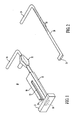
- the brake or clutch lock anti-theft device of the present invention 10 comprises a base 12 which is placed on the floor of the vehicle adjacent to the brake pedal and shaft 13. The base 12 thereby is placed flush to the floorboard of the vehicle directly below the brake pedal and pedal shaft (arm) 13.
- U-shaped steel housing 14 Extending from the base 12 is a U-shaped steel housing 14 which extends downward.
- the U-shaped housing comprises two legs 16, 18.
- One leg 16 of the U-shaped housing is shorter than the other 18 thereby defining an opening 20 which extends to a slot 22 defined by the space between the legs of the U-shaped housing.
- the opening 20 facilitates the placement and removal of the brake pedal shaft 13.
- slot 22 should have an approximate width of the steel brake pedal shaft 13 such that the brake pedal shaft 13 extends through the slot and up to a extended position. In this position, the brake pedal can be depressed freely as it extends downward through said slot 22.
- the invention further comprises a locking mechanism 24 associated with a second leg 18 of the U-shaped housing.
- the second leg 18 of the U-shaped housing 14 includes a cylindrical tube 24 designed to encased a slidable locking pin 26 which is attached to the end of an extendible rod 28.
- the rod 28 contains machined lock ratchets or serrations 30 which extend out the tube of the rectangular steel housing to a locking mechanism 32.
- the second end of the rod 28 comprises a handle 34 which is used to pull the rod upward.
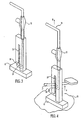
- the preferred locking mechanism or means 32 which is utilized in the present invention may be a commercially available key operated steering wheel locking mechanisms. There are other locking mechanisms suggested by the present invention including combination locks. Locking mechanism or means 32 locks the machine locked ratchets 30 at the appropriate point. As shown most clearly in Figure 4, as the rod 28 extends upward, the pin 26 enters the slot 22, pulls up (Arrow A) and secures the bottom of the brake petal shaft 13 in an upward or unextended position so that it cannot be depressed. In this position, after being locked into place by pin 26, the brake pedal shaft cannot be depressed. Because the pedal cannot be depressed, the car cannot be placed in gear in vehicles containing BPSI and cannot activate the brake to stop the vehicle.
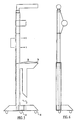
- FIG. 5 An alternative embodiment of the present invention is shown in Figures 5 and 6. As shown in Figure 5, the base 12 and bottom of leg 16 are beveled at 45 degree angles so that the brake pedal shaft 13 can more easily be guided into and out of the slot 22 when the device is place on and removed from the brake pedal shaft 13.
- This embodiment further incorporates a means 36 for enabling the driver to press the device into the floorboard or carpet of the vehicle.
- means 36 comprises a foot rest 36 which extends horizontally from the top of leg 16.
- This extension 36 provides a sufficient surface area 38 for the foot of an operator to press downward and my include a gripping top surface.
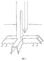
- This embodiment further incorporates studs 40 which extend downward from the base 12 and which facilitate the positioning of the device against a carpeted floor. The studs 40 prevent the device from moving with respect to the floor.
- the device may also incorporate cleats 42 which are cut into the bottom of the base 12.
- this embodiment incorporates a triangular base design in which the legs go to the left, right and straight back. The triangular base design provides maximum support and strength in operation and use.
- the operation of the present invention is now described with reference to the enclosed Figures and most particularly Figures 3 through 6.
- the driver or operator desiring to utilize the device 10 will unlock the device and lower the pin 26 all the way down to the base 12 via the handle.
- the base 12 will then be placed on the floor board 35 under the brake and shaft 13.
- the brake pedal shaft will then extend through the opening 20 in the U-shaped housing and into the slot 22 with the base positioned squarely on the floor board of the vehicle.
- the operator will then pull up the handle 34 (Arrow B) thus raising the locking pin 26 upward into the slot 22 and securing the base pedal 13 at its bottom in an upward position.
- the operator can place his foot on extension 36 to maximize the downward thrust of the device against the floor board of the vehicle. Studs 40 secure the device against the floorboard or carpet.
- the vehicle operator will then lock the device in this position using the lock mechanism such that the brake pedal cannot be depressed, thereby disabling the operation of the vehicle.
- the device of the present invention may include a protective outer coating composed of vinyl, PTFE, rubber or plastic.
- the present invention has been described in the context of locking the brake of a vehicle.
- the device will be affixed to the clutch of the vehicle in the discussed above. Because the clutch is then locked in an upward position and cannot be depressed, the vehicle cannot be started. Accordingly, the teachings of the present invention are equally applicable to affixation to a clutch in a standard transmission vehicle.
Landscapes
- Engineering & Computer Science (AREA)
- Mechanical Engineering (AREA)
- Braking Elements And Transmission Devices (AREA)
- Arrangement And Mounting Of Devices That Control Transmission Of Motive Force (AREA)
- Mechanical Control Devices (AREA)
- Braking Arrangements (AREA)
- Mechanical Operated Clutches (AREA)
- Lock And Its Accessories (AREA)
- Telephone Function (AREA)
- Burglar Alarm Systems (AREA)
Abstract
Description
Claims (10)
- A device (10) with a base member (12) and locking mechanism (32) for locking the pedal and the pedal shaft (13) of a vehicle and preventing theft of the vehicle comprising a base member (12) for placement on the floorboard (35) of the vehicle beneath the pedal and pedal shaft (13) comprising a U-shaped housing (14) extending downward and defining a slot (22) for receiving the pedal shaft (13) and permitting full extension of the pedal shaft (13) upward through the slot, characterized in that the U-shaped housing has a first arm (19) attached to the base (12) and has a second shorter arm (16) defining a gap (20) for receipt of the pedal shaft (13); and the locking mechanism (23) being associated with the first arm (18) for locking the underside of the pedal shaft (13) within the slot (22) such the pedal shaft (13) cannot be depressed.
- Device according to claim 1, characterized in that the locking mechanism (32) is activated by a key.
- Device according to claim 1, characterized in that the locking mechanism (32) is activated by a combination.
- Device according to any of the preceding claims, characterized in that the first arm (18) has a cylindrical opening (24) there through, a rod (28) extending through said cylindrical opening (24) and being slidable therewith, said rod (28) having a pin (26) which catches the underside of said brake or clutch pedal shaft (13) within the slot (22) and pulls said brake or clutch pedal shaft (13) upward in a decompressed position.
- Device according to claim 4, characterized in that the pin (26) is positioned at the first end of the rod (28), the rod (28) further including a handle (34) at a second end for pulling said rod (28) upward to position the brake pedal shaft (13) in a decompressed position.
- Device according to claim 4, characterized in that the rod (28) is serrated.
- Device according to any of the preceding claims, characterized by an extension (36) for facilitating compression by a foot of an operator against the floorboard (35) of the vehicle.
- Device according to any of the preceding claims, characterized by studs (40) for securing the base (12) against the floorboard (35) of the vehicle.
- Device according to any of the preceding claims, characterized in that the U-shaped housing (14) is constructed of stainless steal.
- Device according to any of the preceding claims, characterized in that the base (12) and the second shorter arm (16) include matable beveled surfaces to facilitate ease of positioning of the brake pedal shaft (13) in the slot.
Applications Claiming Priority (5)
| Application Number | Priority Date | Filing Date | Title |
|---|---|---|---|
| US949009 | 1997-10-10 | ||
| US08/949,009 US5870912A (en) | 1997-10-10 | 1997-10-10 | Anti-theft brake locking device |
| US09/004,666 US5881587A (en) | 1997-10-10 | 1998-01-08 | Anti-theft brake or clutch locking device |
| US4666 | 1998-01-08 | ||
| PCT/US1998/012521 WO1999019643A1 (en) | 1997-10-10 | 1998-06-17 | Anti-theft brake or clutch locking device |
Publications (3)
| Publication Number | Publication Date |
|---|---|
| EP1021663A1 EP1021663A1 (en) | 2000-07-26 |
| EP1021663A4 EP1021663A4 (en) | 2002-05-29 |
| EP1021663B1 true EP1021663B1 (en) | 2004-02-11 |
Family
ID=26673309
Family Applications (1)
| Application Number | Title | Priority Date | Filing Date |
|---|---|---|---|
| EP98930282A Expired - Lifetime EP1021663B1 (en) | 1997-10-10 | 1998-06-17 | Anti-theft brake or clutch locking device |
Country Status (15)
| Country | Link |
|---|---|
| US (2) | US5881587A (en) |
| EP (1) | EP1021663B1 (en) |
| JP (1) | JP3335997B2 (en) |
| KR (1) | KR20010031046A (en) |
| CN (1) | CN1158200C (en) |
| AT (1) | ATE259317T1 (en) |
| AU (1) | AU728937B2 (en) |
| BR (1) | BR9812740A (en) |
| CA (1) | CA2306142C (en) |
| DE (1) | DE69821634T2 (en) |
| IL (1) | IL135031A0 (en) |
| PL (1) | PL339758A1 (en) |
| TR (1) | TR200000947T2 (en) |
| TW (1) | TW471410U (en) |
| WO (1) | WO1999019643A1 (en) |
Families Citing this family (24)
| Publication number | Priority date | Publication date | Assignee | Title |
|---|---|---|---|---|
| US5881587A (en) | 1997-10-10 | 1999-03-16 | Lawman Armor Corp. | Anti-theft brake or clutch locking device |
| US5870912A (en) | 1997-10-10 | 1999-02-16 | Lawman Armor Corporation | Anti-theft brake locking device |
| US6089055A (en) * | 1997-10-10 | 2000-07-18 | Vito; Robert A. | Anti-theft brake or clutch locking device |
| US6192724B1 (en) * | 1997-10-10 | 2001-02-27 | Robert A. Vito | Anti-theft brake or clutch pedal locking device |
| US6044671A (en) * | 1998-12-29 | 2000-04-04 | Haire; David L. | Vehicle brake line bleeding aid |
| US6029483A (en) * | 1999-03-31 | 2000-02-29 | Daniels; Darryl Edward | Anti-theft device for automobiles |
| US6202456B1 (en) | 2000-02-18 | 2001-03-20 | Winner International Royalty Llc | Anti-theft device for vehicles |
| TW522944U (en) * | 2001-03-13 | 2003-03-01 | Chan Hau Entpr Co Ltd | Lock for vehicle |
| US6662894B2 (en) | 2001-06-15 | 2003-12-16 | Watchara Chantrasuwan | Automotive brake/clutch lock |
| US6679089B2 (en) | 2001-10-19 | 2004-01-20 | Robert A. Vito | Type of automobile anti-theft device |
| USD493354S1 (en) | 2001-10-19 | 2004-07-27 | Robert A. Vito | Lock assembly component |
| USD493692S1 (en) | 2001-10-19 | 2004-08-03 | Robert A. Vito | Lock assembly component |
| USD465721S1 (en) | 2001-12-07 | 2002-11-19 | Robert A. Vito | Anti-theft device |
| US6516642B1 (en) | 2001-12-07 | 2003-02-11 | Robert A. Vito | Column security device |
| US6460385B1 (en) | 2001-12-07 | 2002-10-08 | Robert A. Vito | Column lock device |
| USD458529S1 (en) | 2001-12-07 | 2002-06-11 | Robert A. Vito | Anti-theft device |
| US6575002B1 (en) | 2002-07-19 | 2003-06-10 | American Auto Accessories, Inc. | Vehicle pedal lock and method therefor |
| US7476331B2 (en) * | 2005-02-09 | 2009-01-13 | E I Du Pont Nemours And Company | Compositions comprising 1,1,1,2,2,3,4,5,5,6,6,7,7,7-tetradecafluoroheptane and uses thereof |
| SE532688C2 (en) * | 2007-02-02 | 2010-03-16 | Tino Gurb | Timer device |
| CN101952146A (en) * | 2007-12-21 | 2011-01-19 | 理查德·奥列弗 | vehicle immobilization system |
| CN101915026A (en) * | 2010-07-15 | 2010-12-15 | 翁文广 | Novel automobile brake and clutch lock |
| CN102991454B (en) * | 2012-07-09 | 2016-01-06 | 李吉源 | Direct-insertion automobile pedal lock |
| CN102923093B (en) * | 2012-08-01 | 2015-06-17 | 李云 | Pedal lock for car anti-theft |
| CN103129519A (en) * | 2013-01-31 | 2013-06-05 | 李吉源 | Multifunctional automobile pedal lock |
Family Cites Families (45)
| Publication number | Priority date | Publication date | Assignee | Title |
|---|---|---|---|---|
| GB160160A (en) * | 1920-03-12 | 1921-12-29 | Joseph Maceska | Improvements in and relating to automobile locks |
| FR862868A (en) * | 1939-01-12 | 1941-03-18 | Auto theft security device | |
| US2330536A (en) * | 1941-06-16 | 1943-09-28 | Maximilian E Zimmermann | Means for locking vehicles against self-propulsion |
| US3245239A (en) | 1962-12-27 | 1966-04-12 | Zaidener Kitty | Anti-theet device for road vehicles |
| GB1033994A (en) | 1964-04-18 | 1966-06-22 | Nuneaton Engineering Company L | Ground-engaging support for a post |
| US3889499A (en) * | 1974-11-01 | 1975-06-17 | William H Cramer | Automobile accelerator locking device |
| US4040675A (en) * | 1976-07-26 | 1977-08-09 | Raymond Richmond | Anti-theft vehicle brake-supervising device |
| FR2419846A1 (en) | 1978-03-15 | 1979-10-12 | Garces Guy | Antitheft device for car - has two box-like parts, one housing clutch pedal and one lock for locking rod |
| FR2422529A1 (en) * | 1978-04-13 | 1979-11-09 | Leclert Bernard Raymond | Antitheft device for vehicles - immobilises clutch pedal in either high or low position |
| GB2023520A (en) | 1978-04-25 | 1980-01-03 | Stoodley J | Vehicle Anti-Theft Locking Arrangement |
| FR2443946A1 (en) | 1978-12-15 | 1980-07-11 | Sourbe Jean Pierre | Compact anti-theft vehicle clamp - locks clutch and brake pedal levers together against chassis floor |
| GB2091656A (en) | 1981-01-24 | 1982-08-04 | Cowie David Black | Vehicle anti-theft device |
| US4493198A (en) * | 1982-09-03 | 1985-01-15 | Brown William B | Anti-theft lock for pedal operated apparatus |
| FR2579943A1 (en) | 1985-04-04 | 1986-10-10 | Mazeirat Jean | Anti-theft device for motor vehicles, acting by locking the control pedals |
| FR2580243A1 (en) | 1985-04-10 | 1986-10-17 | Desfarges Serge | Anti-theft safety device for a motor vehicle |
| US4779435A (en) * | 1985-09-04 | 1988-10-25 | Farrow Robert T | Anti-theft device for road vehicles |
| IT1224564B (en) * | 1988-11-15 | 1990-10-04 | Riccitelli Guglielmo | FOR VEHICLES WITH AUTOMATIC TRANSMISSION ANTI-THEFT DEVICE LOCK-PEDALS FOR VEHICLES, IN PARTICULAR SUITABLE |
| US4934492A (en) * | 1989-04-10 | 1990-06-19 | Hayes Sheen Michael P | Automatic vehicle brake lock system |
| ES2014149A6 (en) | 1989-06-19 | 1990-06-16 | Gusine Juan Orpi | Anti-theft bar for motor vehicles. |
| AU609372B3 (en) | 1990-07-20 | 1991-03-06 | Ching-Rong Wang | Automobile steering lock with a rod anti-releasing mechanism |
| US5040387A (en) * | 1990-10-18 | 1991-08-20 | Knott Lock Corporation | Vehicle brake lock assembly |
| GB9109139D0 (en) * | 1991-04-27 | 1991-06-12 | Hellewell M R | Lock fast |
| FR2681823A1 (en) | 1991-09-26 | 1993-04-02 | Bosch Jose | Antitheft device for motor vehicles |
| DE9215118U1 (en) | 1992-11-06 | 1992-12-17 | Link, Wolfgang, 7401 Pliezhausen | Car anti-theft device |
| US5267458A (en) * | 1992-12-28 | 1993-12-07 | Heh Mao Lin | Car lock multiple locking purposes |
| US5345796A (en) * | 1993-03-08 | 1994-09-13 | Chieh Peter T C | Vehicle brake-pedal locking device |
| US5354031A (en) | 1993-03-29 | 1994-10-11 | Dayva International, Inc. | Low-profile umbrella base |
| US5537846A (en) * | 1993-08-26 | 1996-07-23 | Simon; David A. | Control pedal disabling device |
| FR2719005B1 (en) | 1994-04-25 | 1996-09-20 | Alfredo Mellini | Auto mechanical anti-theft device blocking the brake and clutch pedals. |
| IT1277849B1 (en) * | 1994-09-19 | 1997-11-12 | Guglielmo Riccitelli | ANTI-THEFT FOR LOCKING THE STEERING WHEEL OF ANY KIND OF VEHICLE. |
| US5653133A (en) * | 1995-10-16 | 1997-08-05 | Passantino; Frank | Steering wheel and brake locking device for road vehicles |
| US5979197A (en) | 1995-10-24 | 1999-11-09 | Mellini; Alfredo | Vehicle anti-theft device for blocking at least a pedal arm |
| FR2744409B1 (en) * | 1996-02-07 | 1998-04-24 | Mellini Alfredo | ANTI-THEFT DEVICE FOR VEHICLES, FOR LOCKING AT LEAST ONE PEDAL |
| US5704233A (en) * | 1996-05-06 | 1998-01-06 | Farshad; Fred F. | Anti-theft device for vehicles |
| US5906121A (en) | 1996-08-29 | 1999-05-25 | Mankarious; Adel H. | Pedal lock anti-theft apparatus for vehicles |
| US5715710A (en) * | 1996-11-22 | 1998-02-10 | De Lucia; Achille A. | Portable anti-theft device for motor vehicle |
| US5950463A (en) | 1997-02-12 | 1999-09-14 | Glazier; James | Vehicle brake locking apparatus |
| US5778706A (en) | 1997-06-27 | 1998-07-14 | Testa; Troy | Marine propeller anti-theft device |
| US5881587A (en) | 1997-10-10 | 1999-03-16 | Lawman Armor Corp. | Anti-theft brake or clutch locking device |
| US5870912A (en) | 1997-10-10 | 1999-02-16 | Lawman Armor Corporation | Anti-theft brake locking device |
| US6089055A (en) | 1997-10-10 | 2000-07-18 | Vito; Robert A. | Anti-theft brake or clutch locking device |
| US6192724B1 (en) | 1997-10-10 | 2001-02-27 | Robert A. Vito | Anti-theft brake or clutch pedal locking device |
| DE29719904U1 (en) | 1997-11-08 | 1998-02-12 | Bilgery GmbH, 35428 Langgöns | Umbrella base |
| US5911765A (en) | 1997-12-03 | 1999-06-15 | Scott D. Jacobson | Control pedal disabling device |
| US6202456B1 (en) | 2000-02-18 | 2001-03-20 | Winner International Royalty Llc | Anti-theft device for vehicles |
-
1998
- 1998-01-08 US US09/004,666 patent/US5881587A/en not_active Ceased
- 1998-06-10 TW TW90200395U patent/TW471410U/en not_active IP Right Cessation
- 1998-06-17 BR BR9812740A patent/BR9812740A/en not_active Application Discontinuation
- 1998-06-17 JP JP2000516165A patent/JP3335997B2/en not_active Expired - Fee Related
- 1998-06-17 KR KR1020007003869A patent/KR20010031046A/en not_active Withdrawn
- 1998-06-17 EP EP98930282A patent/EP1021663B1/en not_active Expired - Lifetime
- 1998-06-17 DE DE1998621634 patent/DE69821634T2/en not_active Expired - Fee Related
- 1998-06-17 PL PL33975898A patent/PL339758A1/en unknown
- 1998-06-17 CA CA002306142A patent/CA2306142C/en not_active Expired - Fee Related
- 1998-06-17 TR TR200000947T patent/TR200000947T2/en unknown
- 1998-06-17 IL IL13503198A patent/IL135031A0/en unknown
- 1998-06-17 AU AU79706/98A patent/AU728937B2/en not_active Ceased
- 1998-06-17 WO PCT/US1998/012521 patent/WO1999019643A1/en not_active Ceased
- 1998-06-17 AT AT98930282T patent/ATE259317T1/en not_active IP Right Cessation
- 1998-06-17 CN CNB988100177A patent/CN1158200C/en not_active Expired - Fee Related
-
2001
- 2001-03-15 US US09/808,882 patent/USRE38951E1/en not_active Expired - Lifetime
Also Published As
| Publication number | Publication date |
|---|---|
| JP3335997B2 (en) | 2002-10-21 |
| CN1280656A (en) | 2001-01-17 |
| TW471410U (en) | 2002-01-01 |
| JP2001520139A (en) | 2001-10-30 |
| PL339758A1 (en) | 2001-01-02 |
| USRE38951E1 (en) | 2006-01-31 |
| US5881587A (en) | 1999-03-16 |
| CN1158200C (en) | 2004-07-21 |
| IL135031A0 (en) | 2001-05-20 |
| CA2306142A1 (en) | 1999-04-22 |
| ATE259317T1 (en) | 2004-02-15 |
| EP1021663A4 (en) | 2002-05-29 |
| WO1999019643A1 (en) | 1999-04-22 |
| DE69821634T2 (en) | 2004-12-09 |
| AU7970698A (en) | 1999-05-03 |
| EP1021663A1 (en) | 2000-07-26 |
| KR20010031046A (en) | 2001-04-16 |
| TR200000947T2 (en) | 2000-07-21 |
| AU728937B2 (en) | 2001-01-18 |
| BR9812740A (en) | 2000-08-29 |
| CA2306142C (en) | 2002-11-26 |
| DE69821634D1 (en) | 2004-03-18 |
Similar Documents
| Publication | Publication Date | Title |
|---|---|---|
| EP1021663B1 (en) | Anti-theft brake or clutch locking device | |
| US5870912A (en) | Anti-theft brake locking device | |
| US6089055A (en) | Anti-theft brake or clutch locking device | |
| AU751691B2 (en) | Anti-theft brake or clutch pedal locking device | |
| US7412859B2 (en) | Device for immobilising a motor vehicle | |
| US20010005997A1 (en) | Anti-theft brake or clutch pedal locking device | |
| GB2162481A (en) | Vehicle anti-theft device | |
| US20260109317A1 (en) | Anti-theft vehicle pedal locking device | |
| GB2182618A (en) | Securing device for vehicle pedal | |
| MXPA00003473A (en) | Anti-theft brake or clutch locking device | |
| WO2012050430A1 (en) | An apparatus for securing a pedal of a vehicle | |
| AU782967B2 (en) | Vehicle anti-theft device | |
| US20030115916A1 (en) | Anti-theft brake or clutch pedal locking device | |
| HK1032811A (en) | Anti-theft brake or clutch locking device |
Legal Events
| Date | Code | Title | Description |
|---|---|---|---|
| PUAI | Public reference made under article 153(3) epc to a published international application that has entered the european phase |
Free format text: ORIGINAL CODE: 0009012 |
|
| 17P | Request for examination filed |
Effective date: 20000419 |
|
| AK | Designated contracting states |
Kind code of ref document: A1 Designated state(s): AT BE CH CY DE DK ES FI FR GB GR IE IT LI LU MC NL PT SE |
|
| AX | Request for extension of the european patent |
Free format text: AL PAYMENT 20000419;LT PAYMENT 20000419;LV PAYMENT 20000419;MK PAYMENT 20000419;RO PAYMENT 20000419;SI PAYMENT 20000419 |
|
| A4 | Supplementary search report drawn up and despatched |
Effective date: 20020411 |
|
| AK | Designated contracting states |
Kind code of ref document: A4 Designated state(s): AT BE CH CY DE DK ES FI FR GB GR IE IT LI LU MC NL PT SE |
|
| 17Q | First examination report despatched |
Effective date: 20020930 |
|
| GRAP | Despatch of communication of intention to grant a patent |
Free format text: ORIGINAL CODE: EPIDOSNIGR1 |
|
| RIC1 | Information provided on ipc code assigned before grant |
Ipc: 7F 16H 57/00 B Ipc: 7B 60R 25/00 A |
|
| GRAS | Grant fee paid |
Free format text: ORIGINAL CODE: EPIDOSNIGR3 |
|
| GRAA | (expected) grant |
Free format text: ORIGINAL CODE: 0009210 |
|
| AK | Designated contracting states |
Kind code of ref document: B1 Designated state(s): AT BE CH CY DE DK ES FI FR GB GR IE IT LI LU MC NL PT SE |
|
| AX | Request for extension of the european patent |
Extension state: AL LT LV MK RO SI |
|
| PG25 | Lapsed in a contracting state [announced via postgrant information from national office to epo] |
Ref country code: NL Free format text: LAPSE BECAUSE OF FAILURE TO SUBMIT A TRANSLATION OF THE DESCRIPTION OR TO PAY THE FEE WITHIN THE PRESCRIBED TIME-LIMIT Effective date: 20040211 Ref country code: LI Free format text: LAPSE BECAUSE OF FAILURE TO SUBMIT A TRANSLATION OF THE DESCRIPTION OR TO PAY THE FEE WITHIN THE PRESCRIBED TIME-LIMIT Effective date: 20040211 Ref country code: FI Free format text: LAPSE BECAUSE OF FAILURE TO SUBMIT A TRANSLATION OF THE DESCRIPTION OR TO PAY THE FEE WITHIN THE PRESCRIBED TIME-LIMIT Effective date: 20040211 Ref country code: CY Free format text: LAPSE BECAUSE OF FAILURE TO SUBMIT A TRANSLATION OF THE DESCRIPTION OR TO PAY THE FEE WITHIN THE PRESCRIBED TIME-LIMIT Effective date: 20040211 Ref country code: CH Free format text: LAPSE BECAUSE OF FAILURE TO SUBMIT A TRANSLATION OF THE DESCRIPTION OR TO PAY THE FEE WITHIN THE PRESCRIBED TIME-LIMIT Effective date: 20040211 Ref country code: BE Free format text: LAPSE BECAUSE OF FAILURE TO SUBMIT A TRANSLATION OF THE DESCRIPTION OR TO PAY THE FEE WITHIN THE PRESCRIBED TIME-LIMIT Effective date: 20040211 Ref country code: AT Free format text: LAPSE BECAUSE OF FAILURE TO SUBMIT A TRANSLATION OF THE DESCRIPTION OR TO PAY THE FEE WITHIN THE PRESCRIBED TIME-LIMIT Effective date: 20040211 |
|
| REG | Reference to a national code |
Ref country code: GB Ref legal event code: FG4D |
|
| REG | Reference to a national code |
Ref country code: CH Ref legal event code: EP |
|
| REG | Reference to a national code |
Ref country code: IE Ref legal event code: FG4D |
|
| REF | Corresponds to: |
Ref document number: 69821634 Country of ref document: DE Date of ref document: 20040318 Kind code of ref document: P |
|
| PG25 | Lapsed in a contracting state [announced via postgrant information from national office to epo] |
Ref country code: SE Free format text: LAPSE BECAUSE OF FAILURE TO SUBMIT A TRANSLATION OF THE DESCRIPTION OR TO PAY THE FEE WITHIN THE PRESCRIBED TIME-LIMIT Effective date: 20040511 Ref country code: GR Free format text: LAPSE BECAUSE OF FAILURE TO SUBMIT A TRANSLATION OF THE DESCRIPTION OR TO PAY THE FEE WITHIN THE PRESCRIBED TIME-LIMIT Effective date: 20040511 Ref country code: DK Free format text: LAPSE BECAUSE OF FAILURE TO SUBMIT A TRANSLATION OF THE DESCRIPTION OR TO PAY THE FEE WITHIN THE PRESCRIBED TIME-LIMIT Effective date: 20040511 |
|
| PG25 | Lapsed in a contracting state [announced via postgrant information from national office to epo] |
Ref country code: ES Free format text: LAPSE BECAUSE OF FAILURE TO SUBMIT A TRANSLATION OF THE DESCRIPTION OR TO PAY THE FEE WITHIN THE PRESCRIBED TIME-LIMIT Effective date: 20040522 |
|
| PGFP | Annual fee paid to national office [announced via postgrant information from national office to epo] |
Ref country code: FR Payment date: 20040608 Year of fee payment: 7 |
|
| PGFP | Annual fee paid to national office [announced via postgrant information from national office to epo] |
Ref country code: GB Payment date: 20040616 Year of fee payment: 7 |
|
| PG25 | Lapsed in a contracting state [announced via postgrant information from national office to epo] |
Ref country code: LU Free format text: LAPSE BECAUSE OF NON-PAYMENT OF DUE FEES Effective date: 20040617 Ref country code: IE Free format text: LAPSE BECAUSE OF NON-PAYMENT OF DUE FEES Effective date: 20040617 |
|
| PGFP | Annual fee paid to national office [announced via postgrant information from national office to epo] |
Ref country code: DE Payment date: 20040624 Year of fee payment: 7 |
|
| PG25 | Lapsed in a contracting state [announced via postgrant information from national office to epo] |
Ref country code: MC Free format text: LAPSE BECAUSE OF NON-PAYMENT OF DUE FEES Effective date: 20040630 |
|
| LTIE | Lt: invalidation of european patent or patent extension |
Effective date: 20040211 |
|
| NLV1 | Nl: lapsed or annulled due to failure to fulfill the requirements of art. 29p and 29m of the patents act | ||
| REG | Reference to a national code |
Ref country code: CH Ref legal event code: PL |
|
| ET | Fr: translation filed | ||
| PLBE | No opposition filed within time limit |
Free format text: ORIGINAL CODE: 0009261 |
|
| STAA | Information on the status of an ep patent application or granted ep patent |
Free format text: STATUS: NO OPPOSITION FILED WITHIN TIME LIMIT |
|
| 26N | No opposition filed |
Effective date: 20041112 |
|
| REG | Reference to a national code |
Ref country code: IE Ref legal event code: MM4A |
|
| PG25 | Lapsed in a contracting state [announced via postgrant information from national office to epo] |
Ref country code: IT Free format text: LAPSE BECAUSE OF NON-PAYMENT OF DUE FEES Effective date: 20050617 Ref country code: GB Free format text: LAPSE BECAUSE OF NON-PAYMENT OF DUE FEES Effective date: 20050617 |
|
| PG25 | Lapsed in a contracting state [announced via postgrant information from national office to epo] |
Ref country code: DE Free format text: LAPSE BECAUSE OF NON-PAYMENT OF DUE FEES Effective date: 20060103 |
|
| PG25 | Lapsed in a contracting state [announced via postgrant information from national office to epo] |
Ref country code: FR Free format text: LAPSE BECAUSE OF NON-PAYMENT OF DUE FEES Effective date: 20060228 |
|
| GBPC | Gb: european patent ceased through non-payment of renewal fee |
Effective date: 20050617 |
|
| REG | Reference to a national code |
Ref country code: FR Ref legal event code: ST Effective date: 20060228 |
|
| PG25 | Lapsed in a contracting state [announced via postgrant information from national office to epo] |
Ref country code: PT Free format text: LAPSE BECAUSE OF NON-PAYMENT OF DUE FEES Effective date: 20040711 |
|
| REG | Reference to a national code |
Ref country code: HK Ref legal event code: WD Ref document number: 1031755 Country of ref document: HK |