JP4560214B2 - Anti-theft brake or clutch pedal lock device - Google Patents
Anti-theft brake or clutch pedal lock device Download PDFInfo
- Publication number
- JP4560214B2 JP4560214B2 JP2000605118A JP2000605118A JP4560214B2 JP 4560214 B2 JP4560214 B2 JP 4560214B2 JP 2000605118 A JP2000605118 A JP 2000605118A JP 2000605118 A JP2000605118 A JP 2000605118A JP 4560214 B2 JP4560214 B2 JP 4560214B2
- Authority
- JP
- Japan
- Prior art keywords
- leg
- pedal
- vehicle
- base
- lock
- Prior art date
- Legal status (The legal status is an assumption and is not a legal conclusion. Google has not performed a legal analysis and makes no representation as to the accuracy of the status listed.)
- Expired - Fee Related
Links
Images


Classifications
-
- B—PERFORMING OPERATIONS; TRANSPORTING
- B60—VEHICLES IN GENERAL
- B60R—VEHICLES, VEHICLE FITTINGS, OR VEHICLE PARTS, NOT OTHERWISE PROVIDED FOR
- B60R25/00—Fittings or systems for preventing or indicating unauthorised use or theft of vehicles
- B60R25/01—Fittings or systems for preventing or indicating unauthorised use or theft of vehicles operating on vehicle systems or fittings, e.g. on doors, seats or windscreens
- B60R25/02—Fittings or systems for preventing or indicating unauthorised use or theft of vehicles operating on vehicle systems or fittings, e.g. on doors, seats or windscreens operating on the steering mechanism
- B60R25/022—Fittings or systems for preventing or indicating unauthorised use or theft of vehicles operating on vehicle systems or fittings, e.g. on doors, seats or windscreens operating on the steering mechanism operating on the steering wheel, e.g. bars locked to the steering wheel rim
- B60R25/0221—Fittings or systems for preventing or indicating unauthorised use or theft of vehicles operating on vehicle systems or fittings, e.g. on doors, seats or windscreens operating on the steering mechanism operating on the steering wheel, e.g. bars locked to the steering wheel rim restraining means joining the steering wheel with another part of the car, e.g. pedals
-
- B—PERFORMING OPERATIONS; TRANSPORTING
- B60—VEHICLES IN GENERAL
- B60R—VEHICLES, VEHICLE FITTINGS, OR VEHICLE PARTS, NOT OTHERWISE PROVIDED FOR
- B60R25/00—Fittings or systems for preventing or indicating unauthorised use or theft of vehicles
- B60R25/002—Locking of control actuating or transmitting means
- B60R25/003—Locking of control actuating or transmitting means locking of control actuating means
- B60R25/005—Locking of control actuating or transmitting means locking of control actuating means of foot actuated control means
-
- Y—GENERAL TAGGING OF NEW TECHNOLOGICAL DEVELOPMENTS; GENERAL TAGGING OF CROSS-SECTIONAL TECHNOLOGIES SPANNING OVER SEVERAL SECTIONS OF THE IPC; TECHNICAL SUBJECTS COVERED BY FORMER USPC CROSS-REFERENCE ART COLLECTIONS [XRACs] AND DIGESTS
- Y10—TECHNICAL SUBJECTS COVERED BY FORMER USPC
- Y10T—TECHNICAL SUBJECTS COVERED BY FORMER US CLASSIFICATION
- Y10T70/00—Locks
- Y10T70/50—Special application
- Y10T70/5611—For control and machine elements
- Y10T70/569—Lever
- Y10T70/573—Single
- Y10T70/5735—Externally mounted locking device
-
- Y—GENERAL TAGGING OF NEW TECHNOLOGICAL DEVELOPMENTS; GENERAL TAGGING OF CROSS-SECTIONAL TECHNOLOGIES SPANNING OVER SEVERAL SECTIONS OF THE IPC; TECHNICAL SUBJECTS COVERED BY FORMER USPC CROSS-REFERENCE ART COLLECTIONS [XRACs] AND DIGESTS
- Y10—TECHNICAL SUBJECTS COVERED BY FORMER USPC
- Y10T—TECHNICAL SUBJECTS COVERED BY FORMER US CLASSIFICATION
- Y10T70/00—Locks
- Y10T70/50—Special application
- Y10T70/5611—For control and machine elements
- Y10T70/5757—Handle, handwheel or knob
-
- Y—GENERAL TAGGING OF NEW TECHNOLOGICAL DEVELOPMENTS; GENERAL TAGGING OF CROSS-SECTIONAL TECHNOLOGIES SPANNING OVER SEVERAL SECTIONS OF THE IPC; TECHNICAL SUBJECTS COVERED BY FORMER USPC CROSS-REFERENCE ART COLLECTIONS [XRACs] AND DIGESTS
- Y10—TECHNICAL SUBJECTS COVERED BY FORMER USPC
- Y10T—TECHNICAL SUBJECTS COVERED BY FORMER US CLASSIFICATION
- Y10T70/00—Locks
- Y10T70/50—Special application
- Y10T70/5889—For automotive vehicles
Abstract
Description
【0001】
発明の分野
本発明は、自動変速機(オートマティックトランスミッション)車両及び標準変速機(スタンダードトランスミッション)車両の両方に特に適した、車両盗難防止(anti-theft)用のブレーキ又はクラッチのペダルロック装置に関する。より詳細には、本発明は、ブレーキ又はクラッチのペダルが押し下げられるのを阻止し、それにより車両を運転不能にする装置に関する。
【0002】
発明の背景
自動車の盗難は世界中で大きな問題となっている。米国連邦捜査局は、20秒ごとに1台の車両が盗まれていると報告している。
【0003】
自動車両の機械式盗難防止装置が急増し、種々のタイプの盗難防止装置が市販されるようになっている。従来のシステムの1種では、ペダルをロックする2個の独立形又は関節形のシューによりブレーキ及びアクセルを機械的にロックしている。そのような装置を用いることによる大きな問題は、ロック装置を操作するために、ドライバーがペダル領域に手を伸ばさなければならないこと、或いは実際に膝の上に身をかがめる必要があること、及びブレーキとアクセル間の距離の相違がこの装置の設置の障害になることである。
【0004】
更に最近になって、ピッキング防止材料から成る長いロッドから構成され、かつ、両端に2個の成形部材を付けて、それぞれを車両のペダル及びステアリングホイールに連結する装置が提案されている。ステアリングホイールとの連結部は、安全錠(ロック)を用いてロックし、これが取り外されるのを防止している。この装置はその特性により、自動変速機を備えた自動車だけでなく、従来の変速機を備えた車両にも使用できるが、主として2つの欠点に影響される。
【0005】
第1に、長さサイズ及び取扱いが面倒なことから、装置を使わないときに連結部を保管することが困難である。第2に、この種の装置は実際に盗難について成績は良くない。事実、鋸などによりステアリングホイールのリムを切断するのは比較的容易である。通常、ステアリングホイールのリムは盗難に対して有効な障害部とはなっておらず、リムの2端を引き離すだけで盗難防止装置を外すことができる。又、このような装置は、構造上の特性により、常に自動変速機を備えた自動車に適用できるものではない。
【0006】
英国特許出願番号第2,091,656号には、車両盗難防止用ペダルロック装置が示されている。これは、安全錠及び横に突出した部材が設けられた上方に延びた第1の支持部材と、第2の支持部材と、を具備しており、第2の支持部材の上を第1の支持部材がスライドする。後者の部材が下側の位置にあるときに、突出部材が第1支持部材の対応部材と協同して車両のペダルをロックする。一方、第2支持部材の下端はベース部材を車両の床に配置するように移動させ得る。
【0007】
又、多数の米国特許がブレーキロック機構について発行された。米国特許第4,040,675号は、認められた手順によりブレーキ液の逆流が許されるまで、ホイールシリンダーからマスターシリンダーへのブレーキ液の逆流を阻止することにより、ブレーキ液によるブレーキ作用を維持する車両盗難防止装置を開示している。
【0008】
米国特許第4,493,198号は、ペダル操作装置の盗難防止ロックを開示している。この発明は、ペダルレバーの周囲を締め付けるように配置された第1、第2の制止体を有している。これら制止体が所定位置でロックされると、装置が制止されない限りペダルは操作できない。
【0009】
米国特許第4,934,492号は、油圧(液圧)ブレーキシステムを有する車両のブレーキをロックする自動ブレーキロック機構を開示している。このシステムには、イグニッションスイッチと協働する安全スイッチが組み込まれていて、車両を正常に運転するには、安全スイッチとイグニッションスイッチの両方を「オン」の位置にして、補助ブレーキ装置を解除しなければならない。
【0010】
米国特許第5,040,387号は、同様に、ブレーキペダルと係合する車両ブレーキロックアッセンブリを開示しており、これは、ブレーキペダルと伸縮自在(入れ子式)に係合してブレーキペダルを適正な場所にロックするU字形端部を備えている。
【0011】
米国特許第5,345,796号は、車両が駆動されないように車両のブレーキペダルを押し下げた位置に機械的に保持する車両のブレーキペダルロック機構を開示している。該装置は水平・垂直に旋回するブレーキペダル揺動アーム連結構造体を備えている。
【0012】
最後になるが、米国特許第5,653,133号は、ステアリングホイールとブレーキを有する車両の盗難防止装置を開示している。この装置は、ブレーキの固定部に可動的に取り付けられたブレーキガード、ブレーキガードに係止された下方細長部材、その下方細長部材にロックされた上方細長部材、及びステアリングホイールとロッキングバーと爪部材の周囲に配置するように適当な距離で配置された幅広のバーを有している。この装置を2個の南京錠で固定したとき、ステアリングホイールとブレーキペダルの動きが抑えられる。
【0013】
上述の装置は全て、車両に能動的に配置しなければならない、所謂、能動的装置である。受動的アラーム(警報機)も最近人気を得ているが、これらの装置は高価であり、又車両が偶発的に衝撃を受けると頻繁に作動してしまう。上述の装置及び技術に加えて、従来技術には、車両が盗まれたことがわかると警察に信号を送る複雑な追跡装置が含まれている。捜査が24時間以上行われても、回収できる保証はない。これらのシステムを設置するには費用がかかり、毎月の監視費用を必要とする。自動車のアラームも同様に費用がかかり、車両の窃盗犯によって作動不能とされることもある。
【0014】
従来技術は車両のブレーキペダルをロックするための機構と発明では充実しているけれども、ドライバー又はオペレーターが膝の上に身体を曲げずに、或いは身をかがめずに、ブレーキ又はクラッチのペダルを押し下げない位置に迅速に固定するように工夫した、簡単で容易なシステムはない。1990年以降製造された多くの自動車は、ブレーキ又はクラッチのペダルを押し下げないと始動できないか、ギアを入れることができないので、そのようなシステムによれば車両が使用できなくなる。
【0015】
従って、本発明は、ドライバー又は車両オペレーターが膝の上に身体を曲げ、又は車両の下に入る必要がなく、ブレーキペダル又はクラッチペダルが押し下げられるのを防止するブレーキペダル又はクラッチペダルのロック機構に向けられる。本発明のこれらの、及び他の目的を、以下の要約及び詳細な説明を参照して説明する。
【0016】
発明の要約
一態様において、本発明は、車両盗難を防止するために車両のブレーキ又はクラッチのペダルをロックする装置である。この装置は、車両のペダル及び前記ペダルを支持するペダル軸の下方で車両の床の上に配置するためのベースと;前記ベースに取り付けられた第2の脚、前記第2の脚より短い第1の脚、及び前記第1の脚と前記第2の脚とを連結し、前記第1の脚と前記ベースとの間の開口部及び前記第1の脚と前記第2の脚との間の溝部を形成する交差部材を有する略U字形のハウジングであって、前記開口部及び前記溝部は、前記ペダル軸を受け入れて前記ペダル軸が前記溝部を通って移動できるように十分に大きい略U字形のハウジングと;車両の始動を可能とするまで十分に前記ペダル軸が押し下げられるのを防止するための前記ペダル軸の下側に十分近い上昇位置と、前記ペダル軸が前記溝部及び開口部を通って移動可能となる後退位置との間で、前記略U字形のハウジング上を選択的に移動可能なロックピンと;前記略U字形のハウジングに連結され、前記ロックピンを少なくとも前記上昇位置で固定するように、前記ロックピンに操作可能に接続されるロックであって、鍵穴を備えた上面を有し、該上面は実質的に前記ベースから反対に離れるように向いているロックと;を有している。
【0017】
他の態様において、本発明は、車両の盗難を防止するために車両のブレーキ又はクラッチのペダルをロックする装置である。この装置は、車両のペダル及び前記ペダルを支持するペダル軸の下方で車両の床の上に配置するためのベースと;前記ベースに取り付けられた第2の脚、前記第2の脚より短い第1の脚、及び前記第1の脚と前記第2の脚とを連結し、前記第1の脚と前記ベースとの間の開口部及び前記第1の脚と前記第2の脚との間の溝部を形成する交差部材を有する略U字形のハウジングであって、前記開口部及び前記溝部は、前記ペダル軸を受け入れて前記ペダル軸が前記溝部を通って移動できるように十分に大きい略U字形のハウジングと;前記略U字形のハウジングを通って移動可能なロッドと;前記ロッドの一端に設けられたロックピンであって、車両の始動を可能とするまで十分に前記ペダル軸が押し下げられるのを防止するための前記ペダル軸の下側に十分近い上昇位置と、前記ペダル軸が前記溝部及び開口部を通って移動可能となる後退位置との間を、前記ロッド上で選択的に移動可能なロックピンと;前記ロッドの他端に設けられたハンドルであって、前記ロッドに対して非直角にて、前記ロッドの一側面に対して横切る方向に延び、単一部品で形成されて前記ロッドより先にひだがなく、継ぎ目がない外面を有するハンドルと;前記略U字形のハウジングに連結され、前記ロックピンを少なくとも前記上昇位置で固定するように前記ロッドを介して前記ロックピンに操作可能に接続されるロックと;を有している。
【0018】
他の態様において、本発明は、車両盗難防止のために車両のブレーキ又はクラッチのペダルをロックする装置である。この装置は、車両のペダル及びペダルを支持するペダル軸の下方で車両の床の上に配置するためのベースと;前記ベースに取り付けられた第2の脚、前記第2の脚より短い第1の脚、及び前記第1の脚と前記第2の脚とを連結し、前記第1の脚と前記ベースとの間の開口部及び前記第1の脚と前記第2の脚との間の溝部を形成する交差部材を有する略U字形のハウジングであって、前記開口部及び溝部は、前記ペダル軸を受け入れて前記ペダル軸が前記溝部を通って移動できるように十分に大きい略U字形のハウジングと;ロックピンとロックとを備えたロック機構であって、前記ロックピンは、前記ペダル軸が操作可能に押し下げられるのを防止するための前記ペダル軸の下側に十分近い上昇位置と、前記ペダル軸が前記溝部及び前記開口部を通って移動可能となる後退位置との間で、前記略U字形のハウジング上を選択的に移動可能であり、前記ロックは、前記略U字形のハウジングに連結され、前記ロックピンを少なくとも前記上昇位置で固定するように前記ロックピンに操作可能に接続され、前記ロックは、鍵穴を備えた上面を有し、該上面は実質的に前記ベースから反対に離れるように向いているロック機構と;を有している。
【0019】
好適な実施態様の詳細な説明
本発明のブレーキ用盗難防止装置について添付図面を参照して説明する。各図面において、同じ符号を用いることができる場合には同じ符号を用いる。概して、本発明は、自動車両のブレーキペダル又はクラッチペダルを上昇状態、即ち、押し下げられていない状態でロックするように特に設計された装置である。
【0020】
1990年以来、北米で販売するために製造された多くの車両は、車両のブレーキペダルを押し下げなければ始動できない。自動変速機(オートマティックシフトトランスミッション)を備えた車両においては、この特徴を「ブレーキ・ペダル・シフト・インターロック」、又はBPSIと呼んでいる。多くの非自動変速機、即ち、「標準変速機(スタンダードトランスミッション)」車両は、「クラッチ・ペダル・スタート・インターロック」、又はCPSIと呼ばれる同様の機能を有しており、これは、車両を始動する前にクラッチペダルを押し下げることを必要とする。本発明は両タイプの車両に適用できる。基本的に、本発明は、任意の車両のブレーキペダル、又は標準変速機車両のクラッチペダルが、操作可能な程度まで押し下げられること、即ち、CPSI又はBPSIを不作動にするのに十分な程度まで押し下げることを防止して車両の始動及び/又は運転を妨げることで、BPSI又はCPSIを利用するように特別に設計されている。又、本発明は、BPSI又はCPSIを持たない車両においても作動するように設計されている。つまり、盗難を見越して単にブレーキ又はクラッチのペダルが操作可能な程度まで押し下げられるのを阻止するだけで、通常通りブレーキをかけること、又はトランスミッションをシフトすることを、それぞれ行えないようにする。
【0021】
本発明の特徴は、装置の設置又は調節のためにドライバー又はオペレーター(操作者)が手又は膝の上に身を曲げる、又はかがみ込む必要がなく、車両の運転席から快適にドライバー又はオペレーターが使用できるように意図されていることである。以下、通常の自動車において本発明を説明するが、本発明の教示事項は、スポーツ用車両、バン、ピックアップトラック、及び大型トラックを含めて、ブレーキペダル又はクラッチペダルのアーム若しくは軸(シャフト)を有する全形式の自動車に同様に適用できることを理解されたい。
【0022】
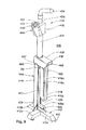
ここでは、説明のために、ブレーキペダルを上方位置でロックし、それによって、例えば、車両のBPSIを非作動とする装置として本発明を記載する。図1〜図4には、ブレーキ又はクラッチロック盗難防止装置10の第1の例(参考例)が示されている。この装置は、ベース(基部)12を有し、ベース12は、ブレーキペダル11及びペダル11を支持する軸13に隣接して(即ち、下方)で、車両の床の上に安定して配置し得るように構成されている。本発明をブレーキペダル11又はクラッチペダル(図示せず)のいずれかに適用した場合の例示を意図して、ブレーキペダル11及び軸13を用いるが、それに限定することを意図するものではない。ベース12は、装置10を安定して支えるために、ブレーキペダル11及びペダル軸13の真下で、車両の床と同一面に配置するように構成されている。
【0023】
略U字形のハウジング14がベース12から延在している。U字形のハウジング14は、ベース12に取り付けられた第2の脚18、その第2の脚18より短い第1の脚16、及び第1の脚16と第2の脚18を連結し、第1の脚16とベース12との間の間隙若しくは開口部20及び第1の脚16と第2の脚18との間の溝部22を形成する交差部材(クロス部材)36を備えている。開口部20はブレーキペダル軸13の配置又は取り外しを容易にしている。一例では、溝部22は、ペダル軸13が溝部22を通って伸長し、又伸長した位置まで延びるように、ペダル軸13とほぼ同じ幅にすべきである。換言すれば、開口部20と溝部22は、ブレーキペダル軸13を受け入れて、ペダル軸13が溝部22を通って移動可能なように十分大きくする。伸長した位置では、ブレーキペダル11は、溝部22を通って下方に延びる(達する)ように、自由に押し下げることができる。
【0024】
本発明は更に、U字形のハウジング14の第2の脚18と連結された、全体として符号32で示されるロック機構を有している。ロック機構は、ロックシリンダー52を含むロックハウジング46を備えたロック44を有している。U字形のハウジング14の第2の脚18とロック44との間には、円筒管(チューブ)24が延在している。第2の脚18、円筒管24、及びロックハウジング46は、個々の部品から組み立てられた一体の組立体(アッセンブリ)であり、好ましくは互いに溶接されている。円筒管24は円筒形である必要はなく、溝形部材(溝形鋼材:チャンネルストック)、箱形断面部材(ボックスセクションストック)などを含む任意の中空構造部材でも良いこと、及び第2の脚18と円筒管24とを単一部品(図示せず)から作製し得ることは当業者には理解されるであろう。
【0025】
又ロック機構32には、スライド(滑動)可能なロックピン26が含まれ、このロックピン26は、円筒管24、第2の脚18及びロックハウジング46を通るロッド(棒)28の第1の端部に設けられている。又、ロッド28は、ロックラチェット(歯止めつめ)或いはセレーション(鋸歯状切り欠き)30を備えている。このセレーション30は、好ましくは、ロッド28の中間部分に沿って、少なくともロックピン26の上昇した位置と下降若しくは後退した位置との間で、セレーション30がロックハウジング46を通過する位置に機械加工されている。ロッド28の第2の端部は、好ましくはハンドル34を有し、このハンドル34は、ベース12に対してロッド28を上方に引っ張り、又はロッド28を下方に押し下げるのに用いられる。本発明で用いられる好ましいロック機構32には、可動ラッチ(かんぬき)部材を備えた市販のキー操作形ステアリングホイールロックシリンダーを含めて良い。これは、セレーション30に解除可能に係合することができる。コンビネーションロック(組み合わせ錠)を含む他のロックを本発明に使用することも考えられる。
【0026】
ロック機構32は、ロック解除状態とロック状態の両方を有している。ロック解除状態では、ロッド28がロックハウジング46を通って自由にスライドする。ロック解除状態では、ロックピン26が開口部20又は溝部22の障害にならないようにロッド28を位置決め(即ち、後退)させることにより、盗難防止装置10の取り付け、取り外しを行うことができる。装置10の取り付け、取り外しの間、ベース12がロックピン26を完全に受け入れることが好ましいが、ピン26の完全な後退は必ずしも必要でないこと、及び後のいくつかの図で示すように部分的な後退のみで十分であり得ることを理解されたい。ロック状態では、以下で十分に論じているように、ロック44がラチェット30を適当な位置でロックする。図4に特に明確に示しているように、ロッド28が上方向に移動して、ベース12から離れると、ロックピン26が溝部22に入り、上方に移動して(矢印A)、これによりペダル軸13の下面(底面)を、上方、即ち、伸長した、即ち、操作不能の位置に保持し、ペダル11を操作可能に押し下げることができなくなる。ペダル11を操作可能に押し下げることができないので、BPSIを用いている車両ではギアを入れることができず、CPSIを用いている車両では始動できない。又、BPSI又はCPSIを付けた車両と付けない車両とにおいて、ブレーキ又はクラッチのペダル11のいずれかを押し下げて車両にブレーキを掛けるか、標準変速機をシフトすることができないので、正常に運転することはできない。
【0027】
後述する盗難防止装置10の各例は、前述の第1の例と同じ基本的特徴を有しているが、以下では特に追加若しくは変更した機能のみを論じる。従って、後述の各例の特徴の説明では、前述の第1の例と同じ内容は繰り返さない。代わりに、全体を通じて同一要素には同一符号を付し、前述の第1の例と後述の各例との差異のみを、類似要素の新規若しくは修正した特徴に対して数百増加した符号を付して説明する。
【0028】
第2の例(好ましい実施例)の装置210を図5及び図6に示す。図5に示すように、ベース212は、3つの脚部212a、212b及び212cを有し、略T字形パターンに構成されている。T字形パターンの利点は、中実の矩形ベース12と比較して、重量低減に加えて、より高い安定性、及び設置された際の盗難防止装置210に対する最大の強度及び支持を提供することである。脚部212a、212b、212cの外側端部、及び第1の脚216の下部(底部)を好ましくは45度の角度で斜めに面取りするとよい。これにより、装置210をペダル軸13に対して取り付け、又取り外す際に、溝部22に対する出し入れのガイドをし易くなる。
【0029】
第2の例の装置210は更に、ドライバーが装置210を車両の床板又はカーペットに押しつけられるように、延長した交差部材236を有する。延長した交差部材236は、第1の脚216の上面(頂部)から水平に延びていて、オペレーターの足で押し下げるのに十分な表面領域(面積)238を提供している。表面領域238にはグリップ性の上部表面を備えていて良いと考えられる。
【0030】
第2の例の装置210は更に、スタッド(鋲)240を有する。スタッド240は、ベース212から下方に延びていて、車両内の床、特にカーペットを敷いた床235に対する装置210の位置決め及び保持を容易にする。スタッド240は、装置210が床に対して移動しないようにする。図7に示すように、装置110には、ベース112の下面(底面)に切り込み、その他の方法で設けた滑り止め(クリート)142をも組み込むことができる。スタッド240と滑り止め142との組み合せは、本発明の範囲と趣旨から逸脱することなく使用できると考えられる。ロックハウジング246はハウジング46よりも小さく、ロッド228と交差するロックシリンダー252を支える。
【0031】
ここで、添付図面、特に、図1〜図7を参照して本発明の作用を説明する。装置10(110又は210)を使用したいドライバー又はオペレーター(操作者)は、装置のロックを解除し、ハンドル34(234)を握ってベース12(112、212)に向けてハンドル34(234)を押すことにより、ピン26(226)をベース12(112、212)まで下方全範囲下げる。次に、一般にステアリングホイール及びステアリングコラム(柱)(図1〜6ではどちらも図示せず)の下方に位置しているペダル軸13の下方で、床35(235)の上にベース12(112、212)を配置する。次に、ペダル軸13をU字形のハウジング14(214)の開口部20(220)を通して溝部22(222)に入れると共に、ベース12(112、212)を車両の床35(235)の真正面に位置させる。次に、ブレーキ(又はクラッチ)ペダル11を適当なときに上方位置でロックするために、オペレーターはハンドル34(234)を上方に引き上げて(図4中矢印A)、ロックピン26(226)を溝部22(222)内へと上方に引き上げ、ペダル軸13の下面を確保する。図5及び図6に示すように、車両の床235に対して装置210の下向きの押圧力を最大限にするために、延長した交差部材236が設けてあれば、その表面領域238にオペレーターは足を置くことができる。滑り止め142(図7)及び/又はスタッド240(図5及び図6)が設けてあれば、それらがペダル11の下方で、カーペット又は床235のその他の表面に対して装置を固定する。次ぎに、車両オペレーターは、ロック機構32(232)を用いて装置10(110、210)をこの位置にロックして、ペダル11を押し下げられないようにし、これによって車両を運転不能にする。
【0032】
図8〜8Bは、第3の例(参考例)の装置310を示す。この例では、第1、第2の脚316、318が実質的に同じ高さになっていて、これにより第1、第2の例に関して示され又説明したベースが必要なくなる。第1の脚316と第2の脚318とは、その下部(底部)において間隔があけられており、ペダル軸13上を滑らせるために傾斜した開口部320を形成し、ペダル軸13が、開口部320の狭くなった端部で始まる溝部322に入ることができるようになっている。ロックピン326は、ロッド328により上方に引っ張られ、それにより、本明細書にて説明される他の例と同様に、ペダル11及びペダル軸13を上方位置でロックする。第3の例の装置310には更に、第1の脚316及び第2の脚318の下部に取り付けられた2個の回転可能な足342が含まれる。この足342は、装置310を旋回可能に支持及び位置決めすることを容易とする。この例の主な特質は、装置310の設置し易さを増すことである。
【0033】
図9〜13は、第4の例(好ましい実施例)に従う盗難防止装置410を示す。第4の例のロック機構432は、ロックピン426及びロック444を備えている。前述の例と同様に、ロックピン426は、U字形のハウジング414の第2の脚418及び円筒ハウジング424を通って動かせる細長ロッド又はシャフト428(図14参照)の一端に設けられている。ロックピン426は、図13に示す上昇位置と、図12に示す後退(収縮)位置との間で、U字形のハウジング414上を選択的に移動可能である。上昇位置では、ロックピン426をペダル軸13の下側に十分近づけて、ペダル軸13が操作可能に押し下げられるのを、即ち、車両を始動及び/又は正常に操縦できるように十分に押し下げられるのを阻止する。後退位置では、ロックピン426はペダル軸13を溝部422及び開口部420を通って移動できるようにする。第4の例の装置410のロックピン426は、ロックピン426の上部のペダル軸接触面426aが、ペダル軸13に向く方向においてほぼ平坦である点で、第1から第3までの例の設計より顕著に改善されている。平坦な軸接触面426aを提供することにより、ロックピン426とペダル軸13との間の接触領域(面積)をより大きくし、これにより、結果として盗難防止装置410をより確実に取り付けることができる。
【0034】
ロックピン426の反対側の、ロッド428の端部にはハンドル434が設けられており、このハンドル434は第1から第3の例で示した前述のハンドル34、234、334とはいくつかの点で異なっている。第1に、ハンドル434は、好ましくはロッド428上にねじ接続(threaded)で装着される。これは、平滑な、穴のある(bored)ハンドル34を平滑なロッド28の端部に固定する接着法が採用されている上述の例(装置10)のような以前の設計よりセキュリティの改善になる。又、溶接(welding)、ろう付け(brazing)などによりハンドル434をロッド428に更に固定することができ、これにより確実な、一体構造にしてロッド428からハンドル434のねじを外せないようにすることをも考えられる。第2に、ハンドル434は、ロッド428に対して非直角に取り付けられる。この設計は、ハンドル34とロッド28とが直角に結合されており、窃盗犯がハンマーを用いてハンドル34を叩いてロック44を破壊する場合がある以前の設計よりも、セキュリティにおいて著しく進歩している。なぜなら、ハンドル34はロッド28に直角であったので、ハンドル34への直撃を容易に達成することができ、全打撃力がロッド28を通してロック44に伝達され、これによりロック44を破壊する。しかしながら、ハンドル434がロッド428に対して非直角である場合、ハンドル434が少なくも打撃力の一部をそらすので、窃盗犯は、ハンドル434又はロッド428の上部(頂部)に対して、ロッド428に平行に直撃を加えることができない。より好ましくは、ロッド428上からの直接の衝撃を更にそらすために、ハンドル434の上面を滑らかに湾曲させて、ベース414から離れるように延ばして、略凸形状とする。第3に、ハンドル434を、継ぎ目がない単一の平滑部品として作製し、ロッド428より上の外面を滑らかに変化させて、ひだ(折り目)なし(クリーズレス)、継ぎ目なし(シームレス)とし、工具(例えば、たがね、鋸又はドリル)と係合する如何なる縁部も有しないようにする。
【0035】
ロック444は、円筒管424を介してU字形のハウジング414と一体に統合されて連結されている。ロック444はハウジング又はヘッド454内に操作用の機械部品を備えたシリンダー452を有する。ロック444は、ロックピン426に対して機能的に結合していて、ロック444とロッド428のセレーション30とがかみ合うことにより、少なくとも上昇位置でロックピン426を固定する。ロック444は、鍵(キー)穴454を備えた上面450を有する。ロック444は、好ましくは円筒形のバレル・タイプのキー458を受け入れる円形の鍵穴454を備えたバレルタイプであり、これにより標準のブランク・タイプ(フラット)キー(図示せず)と比較してセキュリティを著しく高める。バレル・タイプのキーロックは、ピッキング及びスライドハンマーによる破壊に対して特に抵抗力がある。一般に、板金ねじ(シートメタルスクリュー)アタッチメントをスライドハンマーの端部に取り付けて、これをブランク・タイプ(フラット)キーを受け入れるロック内に簡単にねじ込むことができる。そして、スライドハンマーを用いてロックシリンダーをハウジングから引っ張り、セキュリティ装置を破壊する。この技術を用いて、円形鍵穴454及びバレル・タイプのキー458を有するロックを破壊することは非常に困難である。なぜなら、板金ねじ(タッピンねじ)アタッチメントはそのようなロックには容易に取り付けられないからである。
【0036】
ロックハウジング446は、円筒部材424の上部(頂部)から装置410の前に座っているオペレーターに向かって、ベースの脚部412cの方向に延びている。ロック444の上面450及びロックシリンダー452は、実質的にベース412から離れる反対側を向いている。好ましくは、上面450は、ベース412の底部(より詳細には、スタッド440及び滑り止め442の底部)により形成される支持面に対して横切る角度(即ち、直角でもなく、平行でもない)で傾斜している。その面は、約15度から30度の間、より詳細には、約20度から25度の間の角度で、ベース面から下向きに傾斜しているのがよい。上面450を、それゆえにシリンダー452を、実質的にベース412から反対側に離れる方向に向けることによって、ロックが横方向を向いている先のロック盗難防止機構(即ち、最初の3つの例)が遭遇する問題を回避することができる。このような先の設計を用いて、例えば、ロックが左向きで、オペレーターが右利きの場合、オペレーターは利き腕でない手を用いてロックを操作して、盗難防止装置を固定しなければならない。第4の例の装置410のロック444の上面450の配向であれば、オペレーターが利き腕を使用して装置410を車両に固定できるので、この問題は解決できる。更に、実質的にベース412から反対側に離れる方向に上面450を向けることは、鋸でロックハウジング446を通して切断することに対する付加的なセキュリティを提供する。最初の3つの例のような先の設計では、ロックハウジング46はロックシリンダー52をロッド28に直角な方向に配置しており、ロックシリンダー52を囲むロックハウジング46の側面に弓鋸(ハクソー)を係合し易く、これによってロック44を通して切断して装置10を無効にできる。上面450をベース412から反対側に離れる方向に向けることで、弓鋸を係合させ得る如何なる実質的な上面も排除し、更に装置410の上から加えられる打撃をそらすことができる。
【0037】
又、ロックシリンダー452は、ロックシリンダー452を囲んでいるロックハウジング446で保護されている。ロックハウジング446は4面より多い側面を有することが好ましい。例えば、図9では、8側面で上面450の周囲を形成していることを示している。ロッド428に最も近い側面448a(図11)のみが矩形である。上面450を囲む残りの7側面は、三角形又は台形である。他の矩形側面は、側面448b(図11も参照)のみである。4側面より多い側面448、特に矩形ではない側面を提供することにより、上面450と側面448、又はいずれかの側面448間の交線に弓鋸を直接直角に係合させることは非常に困難である。弓鋸の刃(図示せず)と、切断しようとする面とを直角に係合させることは、効率的に切断するのに最適である。
【0038】
ロック444がハウジング446内に別体のラッチ部材を有し、これがロッド428のセレーション30にかみ合ってロッド428とロックピン426とを固定するのがよい。好ましくは、ラッチはスプリングの負荷でセレーションにかみ合い、キー458により回されるシリンダー452の内部部材の回転によってのみ外せる。このように、ラッチはシリンダーの一部ではなく、ラッチを外すにはシリンダー452が必要となる。従って、例えば、ドリルで外すことによってシリンダー452を破壊しても、ラッチを解放することはできない。更に、内部のラッチは、シリンダーを冷やして(凍結させて)収縮させようとする試みからも保護される。
【0039】
ロック444のセキュリティを更に増強するために、ロックハウジング446を強靱な材料、好ましくは硬化鋼で作製して、切断若しくは衝撃で、ロック444が容易には破壊しないようにする。本発明のセキュリティを更に高めるために、第4の例の装置410における、略U字形のハウジング414の脚416、418及び交差部材436、及び円筒管424もまた同様に強靱な材料、好ましくは硬化鋼で作製される。他の強靱な材料(例えば、ステンレス鋼)も本発明の範囲と趣旨から逸脱することなく採用できると考えられるが、硬化鋼は高強度それゆえセキュリティと費用のバランスが最適である。
【0040】
上述のように、U字形のハウジング414の第1の脚416と第2の脚418とは交差部材436により連結されている。第4の例の装置410では、交差部材436は第1、第2の脚416、418のそれぞれに重なっていて、脚416、418に重なる交差部材436の下部縁部437がある。この下部縁部437は、図9〜11によりよく示されるように、溶接部460によって第1、第2の脚416、418の上側に溶接されている。交差部材436を第1、第2の脚416、418と重ねることにより、第1、第2の脚416、418とU字形のハウジング414との剛性が高まる。従って、盗難防止装置410のセキュリティが著しく高まる。図9及び図11に示すように、交差部材436を第1の脚416に、これら両部材の水平交線及び2個所の垂直内部交線に沿って460’で溶接して、盗難防止装置410の構造上の完全性を更に高め、ハウジング414から第1の脚416を外すのを防止することもまた好ましい。好ましくは、交差部材436は、第2の脚418を横断するように十分に延びていて、ロッド428が交差部材436を通ることで、ハウジング414の分解を防止する。
【0041】
第1の脚416と第2の脚418の少なくとも一方を通常の溝形部材(チャンネルストック)から修飾するとよい。図15において、好ましくは、第1の脚416は、対向する平行アーム416a、416bが交差壁部(クロス壁部)416cで連結された略U字形の部材(軸方向の断面で見たとき)とされる。好ましくは、交差壁部416cは、通常の溝形部材について脚416(及び/又は418)の長さ方向の剛性を高めるため、一対のアーム416a、416bの間に、たわみ(屈曲)部、好ましくは外側への湾曲部416dを有している。部材416のように、第1の脚416と第2の脚418の少なくとも一方を、湾曲形状その他の強化した交差壁部を備えた略U字形部材として形成することにより、第1の脚16と第2の脚18を形成するのに3枚の直線的で垂直の壁部から成る単純な溝形部材を用いている先の設計の有意の欠陥を克服している。直線的側面を持つ溝形部材の長手方向の剛性は、屈曲形状の交差壁部416cを備えたU字形構造の場合より著しく低い。従って、単純な溝形部材から作製された第1の脚16と第2の脚18を有するセキュリティ装置は、第1の脚16を曲げることにより破壊し易く、ピン26と曲げたられた脚16との間の溝部22からペダル軸13を外すことができる。又、本発明の範囲と趣旨から逸脱することなく、強度を高めるために、第1の脚416、又は第1、第2の脚416、418を形成するのに脚416、及び壁部416a、416b及び/又は特に416cの他の断面形状を使用できると考えられる。
【0042】
図14は、セレーション30、ロックピン426及びハンドル434を有するロッド428を示す。好ましくは、ロッド428及びピン426は、硬化鋼の単一部品から作製される。前述のように、ハンドル434は強靱な材料の単一部品から別個に形成され、好ましくは硬化鋼から鍛造され、又ロッド428にねじ接続される。
【0043】
盗難防止装置10、210、310、410のいずれも、装置を用いていることを表示するために、車両に取り付けるように構成された標識(バナー)と組み合わせることができる。図16に示すように、標識62は、車両のステアリングホイール64に取り付けるように構成されたカバーであることが好ましい。好ましくは、標識62は、盗難防止装置10、210、310、410の使用によりその車両が移動不能になっていることを、盗もうとしている者に知らせるためにロゴ66その他の識別印を有している。これにより、車内の足を置く空間におけるステアリングホイール及びダッシュボードの下方で使用されることから盗難防止装置がすぐには見えないにも拘わらず、車に相当の損傷を与えた後でのみその行為が無駄であることが判明するような車に、盗もうとする者が無理に入り込もうとはしないであろう。標識は車両のステアリングホイール64に取り付ける必要はなく、フロントガラス(ウィンドシールド)68、その他のウインドウの内面、ダッシュボード70の上のような目に付く位置に取り付け、又はバックミラー72から吊すように構成することもできる。防護の追加手段として、標識62には、車両が防護されていることを示す表示66、好ましくは“PROTECTED(防犯装置付き)”の用語、又は同様のインパクトと意味を持つ用語を含めてもよい。
【0044】
本発明の装置が、ビニル、PTFE(ポリ四フッ化エチレン)、ゴム又はプラスチックを含む外面保護コーティングを備えていて良いことは当業者には理解されよう。
【0045】
以上、本発明を好ましい実施例を参照して説明したが、他の実施例でも本発明の範囲と趣旨とを満たせること、又本発明の本質と範囲は添付した特許請求の範囲に基づいて決定されることを理解されたい。
【図面の簡単な説明】
【図1】 盗難防止装置の第1の例(参考例)の斜視図である。
【図2】 図1に示す盗難防止装置のブレーキロック機構と共に用いられるハンドル及びロックピンの斜視図である。
【図3】 非作動位置にある図1に示された盗難防止装置の斜視図である。
【図4】 作動位置にある図1に示された盗難防止装置の斜視図である。
【図5】 盗難防止装置の第2の例(好ましい実施例)の側面図である。
【図6】 盗難防止装置の第2の例(好ましい実施例)を示す、図5の6−6線に沿った立面図である。
【図7】 図5に示す第2の例(好ましい実施例)で使用される、ベースの他の例の斜視図である。
【図8】 図8は、盗難防止装置の第3の例(参考例)の正面図である。図8Aは、図8に示す盗難防止装置の側面図である。図8Bは、図8及び図8Aに示す盗難防止装置のハンドル/ロッド/ロックピン要素の側面図である。
【図9】 非作動位置にある盗難防止装置の第4の例(好ましい実施例)の斜視図である。
【図10】 図9に示す盗難防止装置の正面図である。
【図11】 図9に示す盗難防止装置の側面図である。
【図12】 ロックピンを完全後退位置にした、図9に示す盗難防止装置の斜視図である。
【図13】 ロックピンを上昇させた作動位置にある、図9に示す盗難防止装置の斜視図である。
【図14】 図9に示す盗難防止装置のロッド、ハンドル及びロックピンの側面図である。
【図15】 図10の14−14線に沿った、図10に示す盗難防止装置の脚部の平面図である。
【図16】 ステアリングホイール上の標識を示す図である。[0001]
Field of Invention
The present invention relates to a brake or clutch pedal lock device for anti-theft vehicle, which is particularly suitable for both automatic transmission (automatic transmission) vehicles and standard transmission (standard transmission) vehicles. More particularly, the present invention relates to an apparatus that prevents a brake or clutch pedal from being depressed, thereby disabling the vehicle.
[0002]
Background of the Invention
Auto theft is a major problem all over the world. The US Federal Bureau of Investigation reports that one vehicle is stolen every 20 seconds.
[0003]
The number of mechanical anti-theft devices for motor vehicles has increased rapidly, and various types of anti-theft devices have become commercially available. One type of conventional system mechanically locks the brake and accelerator with two independent or articulated shoes that lock the pedal. The major problems with using such a device are that in order to operate the locking device, the driver must reach into the pedal area or actually bend over the knee and brake The difference in distance between the vehicle and the accelerator is an obstacle to the installation of this device.
[0004]
More recently, an apparatus has been proposed which is composed of a long rod made of an anti-picking material and which has two molded members at both ends, which are connected to the vehicle pedal and steering wheel, respectively. The connecting portion with the steering wheel is locked using a safety lock (lock) to prevent it from being removed. Due to its characteristics, this device can be used not only for vehicles equipped with automatic transmissions but also for vehicles equipped with conventional transmissions, but is mainly affected by two drawbacks.
[0005]
First, because the length size and handling are cumbersome, it is difficult to store the connection when the device is not in use. Second, this type of device actually does not perform well with theft. In fact, it is relatively easy to cut the rim of the steering wheel with a saw or the like. Usually, the rim of the steering wheel is not an effective obstacle against theft, and the antitheft device can be removed simply by pulling the two ends of the rim apart. Further, such a device is not always applicable to an automobile equipped with an automatic transmission due to structural characteristics.
[0006]
British Patent Application No. 2,091,656 shows a pedal lock device for preventing vehicle theft. This includes a first support member extending upward provided with a safety lock and a laterally projecting member, and a second support member, and the first support member is disposed above the second support member. The support member slides. When the latter member is in the lower position, the projecting member cooperates with the corresponding member of the first support member to lock the pedal of the vehicle. On the other hand, the lower end of the second support member can be moved so as to place the base member on the floor of the vehicle.
[0007]
A number of US patents have also been issued for brake lock mechanisms. U.S. Pat. No. 4,040,675 maintains brake action by brake fluid by preventing brake fluid backflow from the wheel cylinder to the master cylinder until the permitted procedure allows brake fluid backflow. A vehicle antitheft device is disclosed.
[0008]
U.S. Pat. No. 4,493,198 discloses an anti-theft lock for a pedal operating device. This invention has the 1st, 2nd stop body arrange | positioned so that the circumference | surroundings of a pedal lever may be tightened. If these stops are locked in place, the pedal cannot be operated unless the device is stopped.
[0009]
U.S. Pat. No. 4,934,492 discloses an automatic brake lock mechanism for locking a vehicle brake having a hydraulic (hydraulic) brake system. This system incorporates a safety switch that cooperates with the ignition switch, and in order for the vehicle to operate properly, both the safety switch and the ignition switch are in the “on” position and the auxiliary brake device is released. There must be.
[0010]
U.S. Pat. No. 5,040,387 similarly discloses a vehicle brake lock assembly that engages with a brake pedal, which is telescopically engaged with the brake pedal to engage the brake pedal. It has a U-shaped end that locks in place.
[0011]
U.S. Pat. No. 5,345,796 discloses a vehicle brake pedal locking mechanism that mechanically holds the vehicle brake pedal in a depressed position so that the vehicle is not driven. The apparatus includes a brake pedal swinging arm connecting structure that pivots horizontally and vertically.
[0012]
Finally, US Pat. No. 5,653,133 discloses a vehicle antitheft device having a steering wheel and a brake. The device includes a brake guard movably attached to a fixed portion of a brake, a lower elongated member locked to the brake guard, an upper elongated member locked to the lower elongated member, and a steering wheel, a locking bar, and a claw member. And a wide bar arranged at an appropriate distance so as to be arranged around. When this device is fixed with two padlocks, the movement of the steering wheel and the brake pedal is suppressed.
[0013]
All of the devices described above are so-called active devices that must be actively placed in the vehicle. Passive alarms (alarms) have also gained popularity recently, but these devices are expensive and often operate if the vehicle is accidentally impacted. In addition to the devices and techniques described above, the prior art includes complex tracking devices that signal the police when a vehicle is found stolen. There is no guarantee that it can be recovered if the investigation is conducted for more than 24 hours. These systems are expensive to install and require monthly monitoring costs. Car alarms are similarly expensive and vehiclesofIt may be rendered inoperable by thieves.
[0014]
Although the prior art is rich in mechanisms and inventions for locking a vehicle brake pedal, the driver or operator depresses the brake or clutch pedal without bending or bending over the knee. There is no simple and easy system devised to fast fix in no position. Many automobiles manufactured after 1990 cannot be started or geared without depressing the brake or clutch pedal, and such systems render the vehicle unusable.
[0015]
Accordingly, the present invention provides a brake pedal or clutch pedal locking mechanism that prevents the driver or vehicle operator from bending over the knee or entering under the vehicle and preventing the brake pedal or clutch pedal from being depressed. Directed. These and other objects of the invention will be described with reference to the following summary and detailed description.
[0016]
Summary of invention
In one aspect, the present invention is an apparatus for locking a vehicle brake or clutch pedal to prevent vehicle theft. The device includes a vehicle pedal and a base for placement on a vehicle floor below a pedal shaft that supports the pedal;ToAn attached second leg, a first leg shorter than the second leg, and connecting the first leg and the second leg, and an opening between the first leg and the base And a substantially U-shaped housing having a cross member forming a groove between the first leg and the second leg, the opening and the groove receiving the pedal shaft and receiving the pedal A substantially U-shaped housing large enough to allow the shaft to move through the groove; and below the pedal shaft to prevent the pedal shaft from being pushed down sufficiently to allow the vehicle to start Between the raised position close enough and the retracted position where the pedal shaft is movable through the groove and the opening,AbbreviationA locking pin selectively movable on a U-shaped housing;AbbreviationA lock coupled to a U-shaped housing and operably connected to the lock pin to secure the lock pin in at least the raised position, and having a top surface with a keyhole, the top surface substantially And a lock facing away from the base.
[0017]
In another aspect, the present invention is an apparatus that locks a brake or clutch pedal of a vehicle to prevent theft of the vehicle. The device includes a vehicle pedal and a base for placement on a vehicle floor below a pedal shaft that supports the pedal;ToAn attached second leg, a first leg shorter than the second leg, and connecting the first leg and the second leg, and an opening between the first leg and the base And a substantially U-shaped housing having a cross member forming a groove between the first leg and the second leg, the opening and the groove receiving the pedal shaft and receiving the pedal A generally U-shaped housing large enough to allow a shaft to move through the groove;AbbreviationA rod movable through a U-shaped housing; a locking pin provided at one end of the rod for preventing the pedal shaft from being pushed down sufficiently to allow the vehicle to start A raised position close enough to the underside of the pedal shaftA retracted position in which the pedal shaft is movable through the groove and the opening;BetweenTheA lock pin selectively movable on the rod; and a handle provided at the other end of the rod, extending in a direction transverse to one side of the rod at a non-right angle to the rod A handle formed of a single piece and having a seamless outer surface that does not fold before the rod;AbbreviationA lock coupled to a U-shaped housing and operably connected to the lock pin via the rod to secure the lock pin at least in the raised position.
[0018]
In another aspect, the present invention is an apparatus for locking a vehicle brake or clutch pedal to prevent vehicle theft. The apparatus includes a vehicle pedal and a base for placement on a vehicle floor below a pedal shaft supporting the pedal; a second leg attached to the base; a first shorter than the second leg The first leg and the second leg, and an opening between the first leg and the base and between the first leg and the second leg. A substantially U-shaped housing having a cross member forming a groove, wherein the openingas well asThe groove is large enough to receive the pedal shaft and allow the pedal shaft to move through the groove.Almost U-shapedA lock mechanism including a housing; a lock pin and a lock, wherein the lock pin is in a raised position sufficiently close to a lower side of the pedal shaft to prevent the pedal shaft from being operably pushed down; Between the retracted position where the pedal shaft is movable through the groove and the opening,AbbreviationSelectively movable on a U-shaped housing, the lock beingAbbreviationCoupled to a U-shaped housing and operably connected to the lock pin to secure the lock pin at least in the raised position, the lock having a top surface with a keyhole, the top surface being substantially And a locking mechanism facing away from the base.
[0019]
Detailed Description of the Preferred Embodiment
The brake antitheft device of the present invention will be described with reference to the accompanying drawings. In the drawings, the same reference numerals are used when the same reference numerals can be used. In general, the present invention is a device that is specifically designed to lock a brake pedal or clutch pedal of a motor vehicle in a raised state, i.e., not depressed.
[0020]
Many vehicles manufactured since 1990 for sale in North America cannot be started without depressing the brake pedal of the vehicle. In a vehicle equipped with an automatic transmission (automatic shift transmission), this feature is called "brake pedal shift interlock" or BPSI. Many non-automatic transmissions, or “standard transmission” vehicles, have a similar function called “clutch pedal start interlock”, or CPSI, which It is necessary to depress the clutch pedal before starting. The present invention is applicable to both types of vehicles. Basically, the present invention is such that any vehicle brake pedal, or standard transmission vehicle clutch pedal, is depressed to an operable extent, i.e., sufficient to deactivate CPSI or BPSI. Specially designed to utilize BPSI or CPSI by preventing depressing and hindering vehicle starting and / or driving. The present invention is also designed to work in vehicles that do not have BPSI or CPSI. In other words, in anticipation of theft, the brake or clutch pedal is simply prevented from being pushed down to an operable level, so that it is impossible to brake or shift the transmission as usual.
[0021]
A feature of the present invention is that the driver or operator does not need to bend or lean over the hand or knee to install or adjust the device, and the driver or operator can comfortably ride from the driver seat of the vehicle. Is intended to be used. Hereinafter, the present invention will be described in a normal automobile, but the teachings of the present invention include brake pedal or clutch pedal arms or shafts, including sports vehicles, vans, pickup trucks, and heavy trucks. It should be understood that the same applies to all types of cars.
[0022]
Here, for purposes of illustration, the present invention will be described as a device that locks the brake pedal in the upper position, thereby deactivating, for example, the BPSI of the vehicle. 1 to 4TheFirst of rake or clutch lock anti-theft device 10Example (reference example)It is shown. This device has a base (base) 12 that is stably positioned on the vehicle floor adjacent to (ie, below) the
[0023]
A generally
[0024]
The present invention further provides a U-shaped housing.14And a second locking mechanism connected to the
[0025]
The
[0026]
The
[0027]
[0028]
Second example (preferred embodiment)The
[0029]
SecondExampleIn the
[0030]
[0031]
Here, the attached drawings, particularly FIGS.7The operation of the present invention will be described with reference to FIG. A driver or operator who wants to use the device 10 (110 or 210) unlocks the device and operates the handle 34.(234)And hold the
[0032]
8-8B,Third example (reference example)The
[0033]
9-13 areFourth example (preferred embodiment)The
[0034]
A
[0035]
The
[0036]
The
[0037]
The
[0038]
[0039]
To further enhance the security of the
[0040]
As described above, the
[0041]
At least one of the
[0042]
FIG. 14 shows a
[0043]
Any of the
[0044]
Those skilled in the art will appreciate that the apparatus of the present invention may include an outer protective coating comprising vinyl, PTFE (polytetrafluoroethylene), rubber or plastic.
[0045]
Although the present invention has been described with reference to the preferred embodiments, other embodiments can satisfy the scope and spirit of the present invention, and the essence and scope of the present invention are determined based on the appended claims. Please understand that.
[Brief description of the drawings]
[Figure 1]StealFirst of difficulty prevention deviceExample (reference example)FIG.
2 is a perspective view of a handle and a lock pin used together with a brake lock mechanism of the anti-theft device shown in FIG. 1. FIG.
FIG. 3 is a perspective view of the anti-theft device shown in FIG. 1 in a non-actuated position.
4 is a perspective view of the anti-theft device shown in FIG. 1 in an operating position.
[Figure 5]StealSecond of difficulty prevention deviceExample (preferred embodiment)FIG.
[Fig. 6]StealSecond of difficulty prevention deviceExample (preferred embodiment)FIG. 6 is an elevational view taken along line 6-6 of FIG.
7 is a second view shown in FIG.Example (preferred embodiment)Used in the base otherExampleFIG.
[Fig. 8] Fig. 8TheftThird of difficulty prevention deviceExample (reference example)FIG. FIG. 8A is a side view of the antitheft device shown in FIG. FIG. 8B is a side view of the handle / rod / lock pin element of the anti-theft device shown in FIGS. 8 and 8A.
[Fig. 9] Non-actuated positionStealFourth of difficulty prevention deviceExample (preferred embodiment)FIG.
10 is a front view of the anti-theft device shown in FIG. 9;
11 is a side view of the anti-theft device shown in FIG. 9;
12 is a perspective view of the anti-theft device shown in FIG. 9 with the lock pin in a fully retracted position.
13 is a perspective view of the anti-theft device shown in FIG. 9 in an operating position with the lock pin raised.
14 is a side view of the rod, the handle, and the lock pin of the anti-theft device shown in FIG. 9;
15 is a plan view of a leg portion of the anti-theft device shown in FIG. 10, taken along line 14-14 of FIG.
FIG. 16 is a diagram showing a sign on a steering wheel.
Claims (27)
車両のペダル及び前記ペダルを支持するペダル軸の下方で車両の床の上に配置するためのベースと、
前記ベースに取り付けられた第2の脚、前記第2の脚より短い第1の脚、及び前記第1の脚と前記第2の脚とを連結し、前記第1の脚と前記ベースとの間の開口部及び前記第1の脚と前記第2の脚との間の溝部を形成する交差部材を有する略U字形のハウジングであって、前記開口部及び前記溝部は、前記ペダル軸を受け入れて前記ペダル軸が前記溝部を通って移動できるように十分に大きい略U字形のハウジングと、
車両の始動を可能とするまで十分に前記ペダル軸が押し下げられるのを防止するための前記ペダル軸の下側に十分近い上昇位置と、前記ペダル軸が前記溝部と前記開口部を通って移動可能となる後退位置との間で、前記略U字形のハウジング上を選択的に移動可能なロックピンと、
前記略U字形のハウジングに連結され、前記ロックピンを少なくとも前記上昇位置で固定するように前記ロックピンに操作可能に接続されるロックであって、鍵穴を備えた上面を有し、該上面は実質的に前記ベースから反対に離れるように向いているロックと、
を有することを特徴とする前記装置。A device for locking a brake or clutch pedal of a vehicle so as to prevent theft of the vehicle,
A base for placement on a vehicle floor below a pedal of the vehicle and a pedal shaft supporting the pedal;
Second leg attached to the base, a first leg shorter than the second leg, and by connecting the first leg and the second leg, said first leg and said base and A substantially U-shaped housing having a crossing member forming an opening between the first leg and a groove between the first leg and the second leg, the opening and the groove having the pedal shaft A substantially U-shaped housing large enough to receive and move the pedal shaft through the groove;
A raised position sufficiently close to the underside of the pedal shaft to prevent the pedal shaft from being pushed down sufficiently until the vehicle can be started, and the pedal shaft is movable through the groove and the opening. A lock pin that is selectively movable on the substantially U-shaped housing between a retracted position and
A lock coupled to the substantially U-shaped housing and operably connected to the lock pin to fix the lock pin at least in the raised position, the lock having a top surface with a keyhole, A lock facing substantially away from the base; and
A device as described above.
車両のペダル及び前記ペダルを支持するペダル軸の下方で車両の床の上に配置するためのベースと、
前記ベースに取り付けられた第2の脚、前記第2の脚より短い第1の脚、及び前記第1の脚と前記第2の脚とを連結し、前記第1の脚と前記ベースとの間の開口部及び前記第1の脚と前記第2の脚との間の溝部を形成する交差部材を有する略U字形のハウジングであって、前記開口部及び前記溝部は、前記ペダル軸を受け入れて前記ペダル軸が前記溝部を通って移動できるように十分に大きい略U字形のハウジングと、
前記略U字形のハウジングを通って移動可能なロッドと、
前記ロッドの一端に設けられたロックピンであって、車両の始動を可能とするまで十分に前記ペダル軸が押し下げられるのを防止するための前記ペダル軸の下側に十分近い上昇位置と、前記ペダル軸が前記溝部と前記開口部を通って移動可能となる後退位置との間を、前記ロッド上で選択的に移動可能なロックピンと、
前記ロッドの他端に設けられたハンドルであって、前記ロッドに対して非直角にて、前記ロッドの一側面に対して横切る方向に延び、単一部品で形成されて前記ロッドより先にひだがなく、継ぎ目がない外面を有するハンドルと、
前記略U字形のハウジングに連結され、前記ロックピンを少なくとも前記上昇位置で固定するように前記ロッドを介して前記ロックピンに操作可能に接続されるロックと、
を有することを特徴とする前記装置。A device for locking a brake or clutch pedal of a vehicle so as to prevent theft of the vehicle,
A base for placement on a vehicle floor below a pedal of the vehicle and a pedal shaft supporting the pedal;
Second leg attached to the base, a first leg shorter than the second leg, and by connecting the first leg and the second leg, said first leg and said base and A substantially U-shaped housing having a crossing member forming an opening between the first leg and a groove between the first leg and the second leg, the opening and the groove having the pedal shaft A substantially U-shaped housing large enough to receive and move the pedal shaft through the groove;
A rod movable through the generally U-shaped housing;
A lock pin provided on one end of the rod, and a raised position sufficiently close to the underside of the pedal shaft to prevent the pedal shaft is pressed down sufficiently to allow the starting of the vehicle, the between a retracted position the pedal shaft is movable through said groove and said opening, a locking pin selectively movable on said rod,
A handle provided at the other end of the rod, which extends in a direction transverse to one side of the rod at a non-right angle with respect to the rod, and is formed of a single part and has a fold before the rod And a handle having a seamless outer surface,
A lock coupled to the generally U-shaped housing and operably connected to the lock pin via the rod to fix the lock pin at least in the raised position;
A device as described above.
前記ペダル及び前記ペダル軸の下方で車両の床の上に配置するためのベースであり、前記車両の床とかみ合うための下面を備え、前記下面は前記車両の床の上へ前記ベースを保持し易くするための外側に伸長する部材を少なくとも1つ有するベースと、
前記ベースから延在し、前記ペダル軸を受け入れるための溝部をその中に有するハウジングと、
前記ペダルが操作可能に押し下げられないように前記ペダル軸を前記溝部内にロックするためのロック機構と、
を有することを特徴とする前記装置。A device for locking a vehicle pedal supported by a pedal shaft,
A base for disposing the pedal and the pedal shaft on a vehicle floor, comprising a lower surface for engaging with the vehicle floor, the lower surface holding the base on the vehicle floor. A base having at least one member extending outwardly to facilitate;
A housing extending from the base and having a groove therein for receiving the pedal shaft;
A locking mechanism for locking the pedal shaft in the groove so that the pedal is not operably depressed;
A device as described above.
Applications Claiming Priority (5)
| Application Number | Priority Date | Filing Date | Title |
|---|---|---|---|
| US09/268,803 | 1999-03-16 | ||
| US09/268,803 US6089055A (en) | 1997-10-10 | 1999-03-16 | Anti-theft brake or clutch locking device |
| US09/495,098 US6192724B1 (en) | 1997-10-10 | 2000-02-01 | Anti-theft brake or clutch pedal locking device |
| US09/495,098 | 2000-02-01 | ||
| PCT/US2000/006923 WO2000055525A1 (en) | 1999-03-16 | 2000-03-16 | Anti-theft brake or clutch pedal locking device |
Publications (3)
| Publication Number | Publication Date |
|---|---|
| JP2002539025A JP2002539025A (en) | 2002-11-19 |
| JP2002539025A5 JP2002539025A5 (en) | 2007-06-21 |
| JP4560214B2 true JP4560214B2 (en) | 2010-10-13 |
Family
ID=26953334
Family Applications (1)
| Application Number | Title | Priority Date | Filing Date |
|---|---|---|---|
| JP2000605118A Expired - Fee Related JP4560214B2 (en) | 1999-03-16 | 2000-03-16 | Anti-theft brake or clutch pedal lock device |
Country Status (14)
| Country | Link |
|---|---|
| US (3) | US6192724B1 (en) |
| EP (1) | EP1159550B1 (en) |
| JP (1) | JP4560214B2 (en) |
| KR (1) | KR20020010124A (en) |
| CN (1) | CN1149159C (en) |
| AT (1) | ATE260426T1 (en) |
| AU (1) | AU751691B2 (en) |
| BR (1) | BR0009036A (en) |
| CA (1) | CA2368128A1 (en) |
| DE (1) | DE60008505D1 (en) |
| IL (1) | IL145101A0 (en) |
| MX (1) | MXPA01009421A (en) |
| NZ (1) | NZ513756A (en) |
| WO (1) | WO2000055525A1 (en) |
Families Citing this family (31)
| Publication number | Priority date | Publication date | Assignee | Title |
|---|---|---|---|---|
| US5870912A (en) | 1997-10-10 | 1999-02-16 | Lawman Armor Corporation | Anti-theft brake locking device |
| US5881587A (en) | 1997-10-10 | 1999-03-16 | Lawman Armor Corp. | Anti-theft brake or clutch locking device |
| US6192724B1 (en) * | 1997-10-10 | 2001-02-27 | Robert A. Vito | Anti-theft brake or clutch pedal locking device |
| TW522944U (en) * | 2001-03-13 | 2003-03-01 | Chan Hau Entpr Co Ltd | Lock for vehicle |
| US6662894B2 (en) | 2001-06-15 | 2003-12-16 | Watchara Chantrasuwan | Automotive brake/clutch lock |
| US6679089B2 (en) | 2001-10-19 | 2004-01-20 | Robert A. Vito | Type of automobile anti-theft device |
| US6460385B1 (en) | 2001-12-07 | 2002-10-08 | Robert A. Vito | Column lock device |
| US6516642B1 (en) | 2001-12-07 | 2003-02-11 | Robert A. Vito | Column security device |
| US6792780B1 (en) * | 2002-06-25 | 2004-09-21 | Achille A. De Lucia | Universal portable brake pedal locking device for vehicles |
| US6666052B1 (en) * | 2002-09-12 | 2003-12-23 | Chia-Lin Chen | Automobile pedal lockset with vertical entry |
| US20040261476A1 (en) * | 2003-06-26 | 2004-12-30 | Dix Victor George | Big-Un vehicle security device |
| DE102004042417B3 (en) * | 2004-09-02 | 2006-01-05 | Bayerische Motoren Werke Ag | Method for emergency disabling an automatic transmission |
| US6976374B1 (en) * | 2005-01-25 | 2005-12-20 | Christopher Dougherty | Vehicle pedal lock |
| JP4625724B2 (en) * | 2005-06-28 | 2011-02-02 | 株式会社ホンダロック | Vehicle anti-theft device |
| US20080148792A1 (en) * | 2006-12-12 | 2008-06-26 | Ross Davis | Automobile steering wheel and brake pedal locking device |
| WO2011087463A2 (en) * | 2010-01-14 | 2011-07-21 | Kamol Kantajaraniti | Brake/clutch locking device having anti-lock mechanism |
| US20110242587A1 (en) * | 2010-04-05 | 2011-10-06 | Kabushiki Kaisha Toshiba | Image forming device system, printing selection device, print server, image forming device and selection method thereof |
| CN102213042A (en) * | 2010-04-08 | 2011-10-12 | 黄法静 | Vehicle anti-theft lock |
| US8607602B1 (en) * | 2010-09-09 | 2013-12-17 | Godwin Okoye | Passenger portable safety brake |
| CN102910154A (en) * | 2012-02-27 | 2013-02-06 | 付长发 | Antitheft-lock-type fully closed antitheft hand brake |
| MY152210A (en) * | 2012-07-17 | 2014-08-29 | Ng Chee Wah | Anti-theft device |
| CN103129518B (en) * | 2013-01-14 | 2016-06-22 | 苏梅 | The supporting construction of pedal lock |
| CN103129517B (en) * | 2013-01-31 | 2016-08-24 | 李吉源 | The connecting structure of pedal lock |
| CN103273904B (en) * | 2013-04-17 | 2016-08-10 | 苏梅 | Safe self-saving type automobile lock |
| DE102015201540B4 (en) * | 2014-03-07 | 2018-05-30 | Volkswagen Aktiengesellschaft | Method and device for operating a vehicle with an automatic driving mode |
| CN104210459B (en) * | 2014-08-20 | 2016-08-10 | 林嘉伟 | A kind of double structure mechanical automobile theft preventing method and burglary-resisting system thereof |
| USD813646S1 (en) * | 2016-07-24 | 2018-03-27 | Michael Krall | Gate lock |
| KR101935910B1 (en) | 2017-12-29 | 2019-01-07 | 주식회사 유라코퍼레이션 | Device and method for locking accelerator pedal |
| USD926548S1 (en) | 2019-06-28 | 2021-08-03 | Mike Gordon | Locking boot for vehicle wheel |
| USD906080S1 (en) * | 2019-06-28 | 2020-12-29 | Mike Gordon | Locking boot for vehicle wheel |
| US10596996B1 (en) * | 2019-10-30 | 2020-03-24 | Ramon Ruben Lopez | Vehicle brake pedal lock |
Family Cites Families (49)
| Publication number | Priority date | Publication date | Assignee | Title |
|---|---|---|---|---|
| GB160160A (en) | 1920-03-12 | 1921-12-29 | Joseph Maceska | Improvements in and relating to automobile locks |
| FR862868A (en) | 1939-01-12 | 1941-03-18 | Auto theft security device | |
| US2330536A (en) | 1941-06-16 | 1943-09-28 | Maximilian E Zimmermann | Means for locking vehicles against self-propulsion |
| US2744409A (en) | 1953-09-14 | 1956-05-08 | Jr Harry D Wintle | Electromagnetic dynamometer |
| US3245239A (en) | 1962-12-27 | 1966-04-12 | Zaidener Kitty | Anti-theet device for road vehicles |
| GB1033994A (en) * | 1964-04-18 | 1966-06-22 | Nuneaton Engineering Company L | Ground-engaging support for a post |
| US3889499A (en) | 1974-11-01 | 1975-06-17 | William H Cramer | Automobile accelerator locking device |
| US4040675A (en) | 1976-07-26 | 1977-08-09 | Raymond Richmond | Anti-theft vehicle brake-supervising device |
| FR2419846A1 (en) | 1978-03-15 | 1979-10-12 | Garces Guy | Antitheft device for car - has two box-like parts, one housing clutch pedal and one lock for locking rod |
| FR2422529A1 (en) | 1978-04-13 | 1979-11-09 | Leclert Bernard Raymond | Antitheft device for vehicles - immobilises clutch pedal in either high or low position |
| GB2023520A (en) | 1978-04-25 | 1980-01-03 | Stoodley J | Vehicle Anti-Theft Locking Arrangement |
| FR2443946A1 (en) | 1978-12-15 | 1980-07-11 | Sourbe Jean Pierre | Compact anti-theft vehicle clamp - locks clutch and brake pedal levers together against chassis floor |
| GB2091656A (en) | 1981-01-24 | 1982-08-04 | Cowie David Black | Vehicle anti-theft device |
| US4471852A (en) | 1982-02-08 | 1984-09-18 | Ike Schield | Anti-theft devices for automotive vehicles |
| US4493198A (en) | 1982-09-03 | 1985-01-15 | Brown William B | Anti-theft lock for pedal operated apparatus |
| FR2579943A1 (en) | 1985-04-04 | 1986-10-10 | Mazeirat Jean | Anti-theft device for motor vehicles, acting by locking the control pedals |
| FR2580243A1 (en) * | 1985-04-10 | 1986-10-17 | Desfarges Serge | Anti-theft safety device for a motor vehicle |
| US4779435A (en) | 1985-09-04 | 1988-10-25 | Farrow Robert T | Anti-theft device for road vehicles |
| ATE58879T1 (en) | 1985-11-26 | 1990-12-15 | Winner James | STEERING WHEEL LOCK FOR MOTOR VEHICLES. |
| IT1224564B (en) | 1988-11-15 | 1990-10-04 | Riccitelli Guglielmo | FOR VEHICLES WITH AUTOMATIC TRANSMISSION ANTI-THEFT DEVICE LOCK-PEDALS FOR VEHICLES, IN PARTICULAR SUITABLE |
| US4934492A (en) | 1989-04-10 | 1990-06-19 | Hayes Sheen Michael P | Automatic vehicle brake lock system |
| ES2014149A6 (en) | 1989-06-19 | 1990-06-16 | Gusine Juan Orpi | Anti-theft bar for motor vehicles. |
| AU609372B3 (en) * | 1990-07-20 | 1991-03-06 | Ching-Rong Wang | Automobile steering lock with a rod anti-releasing mechanism |
| US5040387A (en) | 1990-10-18 | 1991-08-20 | Knott Lock Corporation | Vehicle brake lock assembly |
| GB9109139D0 (en) | 1991-04-27 | 1991-06-12 | Hellewell M R | Lock fast |
| FR2681823A1 (en) | 1991-09-26 | 1993-04-02 | Bosch Jose | Antitheft device for motor vehicles |
| DE9215118U1 (en) | 1992-11-06 | 1992-12-17 | Link, Wolfgang, 7401 Pliezhausen, De | |
| US5267458A (en) | 1992-12-28 | 1993-12-07 | Heh Mao Lin | Car lock multiple locking purposes |
| CA2152933A1 (en) | 1992-12-30 | 1994-07-21 | Larry Charles Hinnergardt | Treatment of fruits and vegetables by calcium salts |
| US5345796A (en) | 1993-03-08 | 1994-09-13 | Chieh Peter T C | Vehicle brake-pedal locking device |
| US5354031A (en) * | 1993-03-29 | 1994-10-11 | Dayva International, Inc. | Low-profile umbrella base |
| US5537846A (en) | 1993-08-26 | 1996-07-23 | Simon; David A. | Control pedal disabling device |
| FR2719005B1 (en) | 1994-04-25 | 1996-09-20 | Alfredo Mellini | Auto mechanical anti-theft device blocking the brake and clutch pedals. |
| IT1277849B1 (en) | 1994-09-19 | 1997-11-12 | Guglielmo Riccitelli | ANTI-THEFT FOR LOCKING THE STEERING WHEEL OF ANY KIND OF VEHICLE. |
| US5653133A (en) | 1995-10-16 | 1997-08-05 | Passantino; Frank | Steering wheel and brake locking device for road vehicles |
| FR2744409B1 (en) | 1996-02-07 | 1998-04-24 | Mellini Alfredo | ANTI-THEFT DEVICE FOR VEHICLES, FOR LOCKING AT LEAST ONE PEDAL |
| US5979197A (en) * | 1995-10-24 | 1999-11-09 | Mellini; Alfredo | Vehicle anti-theft device for blocking at least a pedal arm |
| US5704233A (en) | 1996-05-06 | 1998-01-06 | Farshad; Fred F. | Anti-theft device for vehicles |
| US5906121A (en) * | 1996-08-29 | 1999-05-25 | Mankarious; Adel H. | Pedal lock anti-theft apparatus for vehicles |
| US5715710A (en) | 1996-11-22 | 1998-02-10 | De Lucia; Achille A. | Portable anti-theft device for motor vehicle |
| US5950463A (en) * | 1997-02-12 | 1999-09-14 | Glazier; James | Vehicle brake locking apparatus |
| US5778706A (en) | 1997-06-27 | 1998-07-14 | Testa; Troy | Marine propeller anti-theft device |
| US5881587A (en) * | 1997-10-10 | 1999-03-16 | Lawman Armor Corp. | Anti-theft brake or clutch locking device |
| US6089055A (en) | 1997-10-10 | 2000-07-18 | Vito; Robert A. | Anti-theft brake or clutch locking device |
| US5870912A (en) * | 1997-10-10 | 1999-02-16 | Lawman Armor Corporation | Anti-theft brake locking device |
| US6192724B1 (en) * | 1997-10-10 | 2001-02-27 | Robert A. Vito | Anti-theft brake or clutch pedal locking device |
| DE29719904U1 (en) * | 1997-11-08 | 1998-02-12 | Bilgery Gmbh | Umbrella base |
| US5911765A (en) * | 1997-12-03 | 1999-06-15 | Scott D. Jacobson | Control pedal disabling device |
| US6202456B1 (en) * | 2000-02-18 | 2001-03-20 | Winner International Royalty Llc | Anti-theft device for vehicles |
-
2000
- 2000-02-01 US US09/495,098 patent/US6192724B1/en not_active Expired - Fee Related
- 2000-03-16 AT AT00916406T patent/ATE260426T1/en not_active IP Right Cessation
- 2000-03-16 BR BR0009036A patent/BR0009036A/en not_active Application Discontinuation
- 2000-03-16 KR KR1020017011692A patent/KR20020010124A/en not_active Application Discontinuation
- 2000-03-16 JP JP2000605118A patent/JP4560214B2/en not_active Expired - Fee Related
- 2000-03-16 MX MXPA01009421A patent/MXPA01009421A/en active IP Right Grant
- 2000-03-16 NZ NZ513756A patent/NZ513756A/en not_active Application Discontinuation
- 2000-03-16 CA CA002368128A patent/CA2368128A1/en not_active Abandoned
- 2000-03-16 DE DE60008505T patent/DE60008505D1/en not_active Expired - Lifetime
- 2000-03-16 IL IL14510100A patent/IL145101A0/en unknown
- 2000-03-16 AU AU37514/00A patent/AU751691B2/en not_active Ceased
- 2000-03-16 CN CNB008044465A patent/CN1149159C/en not_active Expired - Fee Related
- 2000-03-16 EP EP00916406A patent/EP1159550B1/en not_active Expired - Lifetime
- 2000-03-16 WO PCT/US2000/006923 patent/WO2000055525A1/en not_active Application Discontinuation
-
2001
- 2001-01-29 US US09/772,181 patent/US6298696B2/en not_active Expired - Lifetime
- 2001-10-05 US US09/971,729 patent/US6463772B2/en not_active Expired - Lifetime
Also Published As
| Publication number | Publication date |
|---|---|
| US6298696B2 (en) | 2001-10-09 |
| DE60008505D1 (en) | 2004-04-01 |
| EP1159550A4 (en) | 2002-11-06 |
| WO2000055525A1 (en) | 2000-09-21 |
| US6463772B2 (en) | 2002-10-15 |
| ATE260426T1 (en) | 2004-03-15 |
| US20010002543A1 (en) | 2001-06-07 |
| IL145101A0 (en) | 2002-06-30 |
| US6192724B1 (en) | 2001-02-27 |
| EP1159550A1 (en) | 2001-12-05 |
| CN1354825A (en) | 2002-06-19 |
| EP1159550B1 (en) | 2004-02-25 |
| NZ513756A (en) | 2003-05-30 |
| AU751691B2 (en) | 2002-08-22 |
| JP2002539025A (en) | 2002-11-19 |
| MXPA01009421A (en) | 2003-06-06 |
| AU3751400A (en) | 2000-10-04 |
| US20020014097A1 (en) | 2002-02-07 |
| CN1149159C (en) | 2004-05-12 |
| CA2368128A1 (en) | 2000-09-21 |
| BR0009036A (en) | 2001-12-18 |
| KR20020010124A (en) | 2002-02-02 |
Similar Documents
| Publication | Publication Date | Title |
|---|---|---|
| JP4560214B2 (en) | Anti-theft brake or clutch pedal lock device | |
| EP1021663B1 (en) | Anti-theft brake or clutch locking device | |
| US7412859B2 (en) | Device for immobilising a motor vehicle | |
| US5870912A (en) | Anti-theft brake locking device | |
| CA2099793C (en) | Automotive steering wheel anti-theft device | |
| US6089055A (en) | Anti-theft brake or clutch locking device | |
| US20010005997A1 (en) | Anti-theft brake or clutch pedal locking device | |
| US20030115916A1 (en) | Anti-theft brake or clutch pedal locking device | |
| JP2595547Y2 (en) | Bracket for steering column support | |
| GB2300606A (en) | A safety steering wheel | |
| GB2134463A (en) | Security device | |
| JP2000006864A (en) | Burglary preventive device of bicycle | |
| JPH11105756A (en) | Bicycle with anti-theft device | |
| MXPA00003473A (en) | Anti-theft brake or clutch locking device |
Legal Events
| Date | Code | Title | Description |
|---|---|---|---|
| A621 | Written request for application examination |
Free format text: JAPANESE INTERMEDIATE CODE: A621 Effective date: 20070312 |
|
| A521 | Request for written amendment filed |
Free format text: JAPANESE INTERMEDIATE CODE: A523 Effective date: 20070327 |
|
| A131 | Notification of reasons for refusal |
Free format text: JAPANESE INTERMEDIATE CODE: A131 Effective date: 20091208 |
|
| A601 | Written request for extension of time |
Free format text: JAPANESE INTERMEDIATE CODE: A601 Effective date: 20100303 |
|
| A602 | Written permission of extension of time |
Free format text: JAPANESE INTERMEDIATE CODE: A602 Effective date: 20100310 |
|
| A521 | Request for written amendment filed |
Free format text: JAPANESE INTERMEDIATE CODE: A523 Effective date: 20100608 |
|
| TRDD | Decision of grant or rejection written | ||
| A01 | Written decision to grant a patent or to grant a registration (utility model) |
Free format text: JAPANESE INTERMEDIATE CODE: A01 Effective date: 20100629 |
|
| A01 | Written decision to grant a patent or to grant a registration (utility model) |
Free format text: JAPANESE INTERMEDIATE CODE: A01 |
|
| A61 | First payment of annual fees (during grant procedure) |
Free format text: JAPANESE INTERMEDIATE CODE: A61 Effective date: 20100726 |
|
| R150 | Certificate of patent or registration of utility model |
Free format text: JAPANESE INTERMEDIATE CODE: R150 |
|
| FPAY | Renewal fee payment (event date is renewal date of database) |
Free format text: PAYMENT UNTIL: 20130730 Year of fee payment: 3 |
|
| LAPS | Cancellation because of no payment of annual fees |