EP1159549B1 - Spanneinrichtung für zugmittel - Google Patents
Spanneinrichtung für zugmittel Download PDFInfo
- Publication number
- EP1159549B1 EP1159549B1 EP00909202A EP00909202A EP1159549B1 EP 1159549 B1 EP1159549 B1 EP 1159549B1 EP 00909202 A EP00909202 A EP 00909202A EP 00909202 A EP00909202 A EP 00909202A EP 1159549 B1 EP1159549 B1 EP 1159549B1
- Authority
- EP
- European Patent Office
- Prior art keywords
- stopper
- tension arm
- tensioning device
- tension
- support
- Prior art date
- Legal status (The legal status is an assumption and is not a legal conclusion. Google has not performed a legal analysis and makes no representation as to the accuracy of the status listed.)
- Expired - Lifetime
Links
- 238000000034 method Methods 0.000 claims description 8
- 238000005553 drilling Methods 0.000 description 3
- 238000002485 combustion reaction Methods 0.000 description 2
- 230000000694 effects Effects 0.000 description 2
- 238000006243 chemical reaction Methods 0.000 description 1
- 238000013016 damping Methods 0.000 description 1
- 230000002349 favourable effect Effects 0.000 description 1
- 239000012530 fluid Substances 0.000 description 1
- 230000009191 jumping Effects 0.000 description 1
Images
Classifications
-
- F—MECHANICAL ENGINEERING; LIGHTING; HEATING; WEAPONS; BLASTING
- F16—ENGINEERING ELEMENTS AND UNITS; GENERAL MEASURES FOR PRODUCING AND MAINTAINING EFFECTIVE FUNCTIONING OF MACHINES OR INSTALLATIONS; THERMAL INSULATION IN GENERAL
- F16H—GEARING
- F16H7/00—Gearings for conveying rotary motion by endless flexible members
- F16H7/08—Means for varying tension of belts, ropes or chains
- F16H7/10—Means for varying tension of belts, ropes or chains by adjusting the axis of a pulley
- F16H7/12—Means for varying tension of belts, ropes or chains by adjusting the axis of a pulley of an idle pulley
- F16H7/1254—Means for varying tension of belts, ropes or chains by adjusting the axis of a pulley of an idle pulley without vibration damping means
- F16H7/1281—Means for varying tension of belts, ropes or chains by adjusting the axis of a pulley of an idle pulley without vibration damping means where the axis of the pulley moves along a substantially circular path
-
- F—MECHANICAL ENGINEERING; LIGHTING; HEATING; WEAPONS; BLASTING
- F16—ENGINEERING ELEMENTS AND UNITS; GENERAL MEASURES FOR PRODUCING AND MAINTAINING EFFECTIVE FUNCTIONING OF MACHINES OR INSTALLATIONS; THERMAL INSULATION IN GENERAL
- F16H—GEARING
- F16H7/00—Gearings for conveying rotary motion by endless flexible members
- F16H7/08—Means for varying tension of belts, ropes or chains
- F16H2007/0802—Actuators for final output members
- F16H2007/081—Torsion springs
-
- F—MECHANICAL ENGINEERING; LIGHTING; HEATING; WEAPONS; BLASTING
- F16—ENGINEERING ELEMENTS AND UNITS; GENERAL MEASURES FOR PRODUCING AND MAINTAINING EFFECTIVE FUNCTIONING OF MACHINES OR INSTALLATIONS; THERMAL INSULATION IN GENERAL
- F16H—GEARING
- F16H7/00—Gearings for conveying rotary motion by endless flexible members
- F16H7/08—Means for varying tension of belts, ropes or chains
- F16H2007/0846—Means for varying tension of belts, ropes or chains comprising a mechanical stopper
-
- F—MECHANICAL ENGINEERING; LIGHTING; HEATING; WEAPONS; BLASTING
- F16—ENGINEERING ELEMENTS AND UNITS; GENERAL MEASURES FOR PRODUCING AND MAINTAINING EFFECTIVE FUNCTIONING OF MACHINES OR INSTALLATIONS; THERMAL INSULATION IN GENERAL
- F16H—GEARING
- F16H7/00—Gearings for conveying rotary motion by endless flexible members
- F16H7/08—Means for varying tension of belts, ropes or chains
- F16H2007/0876—Control or adjustment of actuators
- F16H2007/0878—Disabling during transport
Definitions
- the present invention relates to a tensioning device for traction means, in particular Timing belts, such as those found in toothed belt drives in motor vehicles be used.
- the present invention further relates to a Procedure for the commissioning of a prestressed tensioning device in particular for a traction drive.
- a tensioning device for timing belts is known in which a tension roller is rotatably mounted on an eccentric.
- the eccentric is pivotally mounted on a support attached to an engine is flanged by means of a screw.
- One arranged on the eccentric Coil spring is on the one hand on the motor and on the other hand on the eccentric supported such that the eccentric with the tensioning roller against the toothed belt is sprung.
- a locking pin is provided in this tensioning device, the tension spring before start-up in a pre-tensioned arrangement holds. After flanging the tensioning device to the motor the locking pin is removed so that the eccentric under the force of Tension spring is spring loaded against the toothed belt.
- the timing belt can do that Loop the toothed belt pulleys of the crankshaft and camshafts. It it is important that the timing belt jumps over the teeth of the timing belt pulleys is prevented, otherwise the tax times in undesirable Modified so that a total failure of the internal combustion engine the result can be.
- To snap the timing belt To avoid is between the tensioning device according to US 48 32 665-A the mentioned bolt and the eccentric arranged a freewheel. If in the run of the toothed belt with which the tensioning pulley works If there are strand forces, the eccentric counteracts the force of the tension spring pivoted. The pinch roller freewheel engages in this direction, so that an undesirably high deflection of the eccentric from the belt drive is prevented.
- a so-called double eccentric tensioner is known from DE 40 15 028 A1 includes a setting eccentric and a work eccentric.
- a jig Fastening hole bolts When installing on the Engine block is arranged with an eccentric by a jig Fastening hole bolts first screwed loosely. With an adjustment tool inserted into a hexagon socket the tensioning device is pivoted against the belt. If this a reaction force acts on the tensioning device. With further The coil spring tightens and the mounting element swivels. The swiveling process continues until the intended one Notches on the flange and a plastic disc overlap. In this There is a protrusion in the middle of a recess of the situation Swivel range of the tension arm. In this default setting, the bolt screwed.
- a belt tensioning device has become known from generic DE 4300 178 C1 a tension arm on which a tension roller is rotatably arranged.
- the tension arm is pivoted on an axis, with a washer is positively connected to the axis and in the axial direction on one Screw head of a screw is supported, which in a blind hole an end face of the axis is formed.
- This axis in turn is over a additional screw can be fixed on a part fixed to the frame.
- the washer has a nose which engages in a recess of the clamping arm, wherein this recess is formed concentrically to the axis in the form of an arc piece is.
- the clamping lever which has a bore, with the help of Insert a pin through the washer recess in the hole to lock the tensioning lever in a pretensioned position. If pulling the pin out is pivoting the tension arm with respect to the axis possible until the washer nose in the circumferential direction against the ends strike the arcuate recess.
- the object of the present invention is therefore to provide a tensioning device, which are simply constructed and can be put into operation reliably is.
- a tensioning device for traction means in particular Timing belt proposed according to claim 1.
- the location of the stopper is now matched to the timing belt drive. Misadjustments, especially due to hysteresis effect, are excluded because the stopper only in the direction is pivoted on the belt and because the stopper together with the Clamping arm is moved.
- the tension arm is pivotally arranged on a support according to claim 1 is, a tension spring on the one hand on the carrier and on the other is supported on the tension arm.
- This arrangement enables biasing the tension spring. If the tension arm, the stopper and the carrier by means of Locking device can be locked together, the following result Advantages: First, the locking can take place in an arrangement in which the Tension spring is preloaded and secondly, a defined angle can already be between the stopper and the tension arm. Because the Disc is rotatable relative to the carrier and can be fixed thereon, becomes a clear one Positioning the stopper when mounting the tensioning device reached.
- the tension arm and the stopper can both each have at least one system be provided, which are provided for striking against each other, wherein the attachments are spaced apart when the tension arm and the stopper are locked together. This distance is just such that after commissioning the clamping device, the swivel angle of the clamping arm from its middle position - at least largely with the position after completing the assembly - out and against the clamping force the tension spring is matched to the toothed belt drive. If so excessive strand forces a strong deflection of the tension arm against the Spring force of the tension spring, this deflection is timely stopped by the stopper or by hitting the systems together. As soon as the strand forces are reduced, the tension arm springs under the spring force the tension spring immediately against the toothed belt, so that jumping of the toothed belt is reliably prevented.
- a particularly simple locking device provides a pin for locking engages in openings of the parts to be locked, the pin except Engagement with the openings can be brought.
- the tension arm, the stopper and the carrier are each provided with a hole which aligned with each other, with the pin passing through this hole. If the tensioning device is installed in the toothed belt drive, only needs the pin is first pulled out of the carrier, the stopper is fixed and then the pen to be pulled completely, so that the commissioning the tensioning device according to the invention can be carried out without further steps.
- the carrier can comprise a base plate which is provided with a bolt is on which the clamping arm is pivotally arranged. Such an arrangement is preferably useful when the base plate to the contour the flange surface of the motor should be adapted.
- the bolt and the base plate are preferably firmly connected.
- the stopper already mentioned can be done in a particularly simple manner be formed by the rotatable disc relative to the bolt, which preferably can be fixed frictionally on the bolt.
- the ability of the disc being rotatable relative to the bolt is required to ensure that the clamping arm and the disc pivot together so far can, until the balance of forces between strand force and tension spring force is set. After that, the washer can be frictionally attached to the bolt become.
- the tension spring can be by a helical torsion spring be formed, which is arranged on the bolt; the coil spring is then on the one hand on the carrier and on the other hand on the one designed as an eccentric Supported arm.
- the locking device sees a pin in front of openings in the disc and the eccentric and of the wearer engages.
- the position of the disc is set against the eccentric as a result of the locking, and also the coil spring can be biased; because the coil spring is on the one hand supported on the carrier and on the other hand on the eccentric and since this the two parts are locked by the pin, the coil spring can not relax.
- the aforementioned fixing of the washer to the bolt is preferably done by means of a screw in a hole provided in the bolt engages, the washer with the screw tightened on the bolt pressed and frictionally connected to this.
- This tensioning device can advantageously be developed by that the screw through the hole designed as a central longitudinal hole passed and with a machine part fixed to the frame, in particular the Engine block that is screwed.
- this screw serves a double Purpose, namely first to fix the tensioning device on the engine block and secondly to fix the washer to the bolt.
- the clamping device described can be particularly favorable suitable for the following procedure for commissioning the clamping device.
- the one provided for this method described below Clamping device has the following features: A clamping arm on which a tension pulley is rotatably mounted; a carrier on which the tension arm is pivotally arranged; a tension spring on the one hand on the carrier and on the other hand is supported on the tension arm; a stopper that one Limited swivel angle of the clamping arm; a releasable locking device, by means of which the clamping arm and the carrier and the stopper can be locked together are.
- the procedure includes the following steps: Locking the tension arm and the carrier with each other in an arrangement in which the tension spring is biased.
- This pre-assembled tensioning device is in the traction drive installed and the belt is placed on the tension pulley. After that the locking described is partially canceled such that only the stopper and the clamping arm remain locked by means of the locking device, under the force of the preloaded tension spring, the tension arm together springs against the traction device with the stopper. Now the stopper is fixed. Subsequently, the lock is released completely, so that the tension arm is pivotable relative to the stopper. The stopper now has an optimal location.
- the existing swivel angle of the tension arm until it hits the stopper, its amount is approximate as large as the pre-assembled clamping device: because with the pre-assembled Clamping device is this swivel angle by locking Clamping arm and stopper fixed together, the stopper according to common Swiveling the tension arm and stopper is fixed.
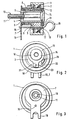
- a tension roller 1 rotatably mounted on a cam 3 via a ball bearing 2.
- the eccentric 3 is on a carrier 4 with the interposition of a slide bearing 5 pivoted.
- the carrier 4 comprises a cylindrical bolt 6 and a base plate 7, which is arranged at one end of the bolt 6 and fixed with this is connected.
- the base plate 7 is used for planting and to prevent rotation the tensioning device compared to an engine block, not shown an internal combustion engine.
- a helical torsion spring 8 is provided, on the one hand on the Base plate 7 is supported and on the other hand engages the eccentric 3.
- the bolt 6 is provided with a central longitudinal bore 9 through which one Screw 10 is passed.
- the screw 10 engages with its threaded section 11 into a threaded bore, not shown, of the engine block.
- On the other end of the bolt 6 is a washer 12 on a shoulder 13 of the Bolt 6 rotatably arranged.
- the disc 12 protrudes slightly axially, so that between a screw head 14 of the screw 10 and the bolt 6 can be clamped when the screw 10 is tightened. The fixation causes the disc 12 to be frictionally connected to the bolt 6 is.
- a pin 15 is provided which the disc 12, the eccentric 3 and the Carrier 4 locked together.
- the base plate 7 of the Carrier 4, the eccentric 3 and the disc 12 each have a bore 16, 17, 18th through which the pin 15 is passed.
- the coil spring 8 biased biased.
- the base plate 7 has a fork-shaped end 19, which is provided for engagement with the engine block, not shown is. Furthermore, this illustration shows that the eccentric 3 with is provided with a raised projection 20 which at least the disc 12 partially overlapped in the axial direction.
- the disc 12 also has a radial directed web 21 on, with the bore 18 for the pin (the in this Representation is not shown) is provided.
- the web 21 and the projection 20 each have a system 22, 23, which are provided for striking against one another are.
- FIG. 3 clearly shows the shape of the base plate 7.
- the screw 10 be provided at its free end with a locking ring, on the one hand is supported on the screw and on the other hand on the bolt 6. On in this way the screw is not only held captive in the bolt, but the axial force of the helical torsion spring 8 is via this locking ring introduced into the screw 10.
Landscapes
- Engineering & Computer Science (AREA)
- General Engineering & Computer Science (AREA)
- Mechanical Engineering (AREA)
- Devices For Conveying Motion By Means Of Endless Flexible Members (AREA)
Description
- Figur 1
- einen Längsschnitt durch eine erfindungsgemäße Spanneinrichtung;
- Figur 2
- eine Ansicht der Spanneinrichtung aus Figur 1 von links und
- Figur 3
- eine Ansicht der Spanneinrichtung aus Figur 1 von rechts.
- 1
- Spannrolle
- 2
- Kugellagerung
- 3
- Exzenter
- 4
- Träger
- 5
- Gleitlager
- 6
- Bolzen
- 7
- Grundplatte
- 8
- Schraubendrehfeder
- 9
- Längsbohrung
- 10
- Schraube
- 11
- Gewindeabschnitt
- 12
- Scheibe
- 13
- Absatz
- 14
- Schraubenkopf
- 15
- Stift
- 16
- Bohrung
- 17
- Bohrung
- 18
- Bohrung
- 19
- gabelförmiges Ende
- 20
- Vorsprung
- 21
- Steg
- 22
- Anlage
- 23
- Anlage
Claims (12)
- Spanneinrichtung für Zugmittel, insbesondere Zahnriemen, mit einem Spannarm (3), auf dem eine Spannrolle (1) drehbar angeordnet ist, und mit einem Stopper (12), der einen Schwenkwinkel des Spannarms (3) begrenzt, wobei eine lösbare Arretiereinrichtung (15) vorgesehen ist, mittels der der Spannarm (3) und der Stopper (12) zum gemeinsamen Verschwenken in eine für den Stopper (12) vorgesehene Position arretiert sind, wobei der Spannarm (3) auf einem Träger (4) schwenkbar angeordnet ist, wobei eine Spannfeder (8) einerseits an dem Träger (4) und andererseits an dem Spannarm (3) abgestützt ist, dadurch gekennzeichnet, dass der Stopper durch eine gegenüber dem Träger (4) drehbare Scheibe (12) gebildet ist, die,vorzugsweise reibschlüssig an dem Träger (4) festlegbar ist.
- Spanneinrichtung nach Anspruch 1, bei der der Spannarm (3) und der Stopper (12) beide je mit wenigstens einer Anlage (22, 23) versehen sind, die zum Anschlagen aneinander vorgesehen sind, wobei die Anlagen (22, 23) der miteinander arretierten Spannarm (3) und Stopper (12) in Schwenkrichtung des Spannarms (3) voneinander beabstandet sind.
- Spanneinrichtung nach Anspruch 1, bei der der Spannarm (3), der Stopper (12) und der Träger (4) mittels der Arretiereinrichtung (15) miteinander arretierbar sind.
- Spanneinrichtung nach Anspruch 1, bei der die Arretiereinrichtung einen Stift (15) umfaßt, der zum Arretieren in Öffnungen (16, 17, 18) der zu arretierenden Teile (4, 12, 3) eingreift, wobei der Stift (15) außer Eingriff mit den Öffnungen (16, 17, 18) bringbar ist.
- Spanneinrichtung nach Anspruch 1, bei der der Träger (4) eine Grundplatte (7) umfaßt, die mit einem Bolzen (6) versehen ist, auf dem der Spannarm (3) schwenkbar angeordnet ist.
- Spanneinrichtung nach Anspruch 5, bei dem der Bolzen (6) und die Grundplatte (7) fest miteinander verbunden sind.
- Spanneinrichtung nach Anspruch 6, bei der der Stopper durch eine gegenüber dem Bolzen (6) drehbare Scheibe (12) gebildet ist, die vorzugsweise reibschlüssig an dem Bolzen (6) festlegbar ist.
- Spanneinrichtung nach Anspruch 7, bei der eine auf dem Bolzen (6) angeordnete Schraubendrehfeder (8) einerseits an dem Träger (4) und andererseits an dem als Exzenter (3) ausgebildeten Spannarm abgestützt ist.
- Spanneinrichtung nach Anspruch 8, bei der die Arretiereinrichtung einen Stift umfaßt, der in Bohrungen (16, 17, 18) der Scheibe (12) und des Exzenters (3) und des Trägers (4) eingreift.
- Spanneinrichtung nach Anspruch 8, bei der eine Schraube (10) in eine im Bolzen (6) vorgesehene Bohrung (9) eingreift, wobei die Scheibe (12) bei angezogener Schraube (10) an den Bolzen (6) angedrückt und reibschlüssig mit diesem verbunden ist.
- Spanneinrichtung nach Anspruch 10, bei der die Schraube (10) durch die als zentrale Längsbohrung (9) ausgeführte Bohrung hindurchgeführt und mit einem gestellfesten Maschinenteil, insbesondere Motorblock, verschraubt ist.
- Verfahren zur Inbetriebnahme einer insbesondere vorgespannten Spanneinrichtung für einen Zugmitteltrieb, - wobei die Spanneinrichtung aufweist:nach den folgenden Schritten:einen Spannarm (3), auf dem eine Spannrolle (1) drehbar gelagert ist,einen Träger (4), auf dem der Spannarm (3) schwenkbar angeordnet ist,eine Spannfeder (8), die einerseits an dem Träger (4) und andererseits an dem Spannarm (3) abgestützt ist,einen Stopper (12), der einen Schwenkwinkel des Spannarms (3) begrenzt undeine lösbare Arretiereinrichtung (15), mittels der der Spannarm (3) und der Träger (4) und der Stopper (12) miteinander arretierbar sindArretieren des Spannarms (3) und des Trägers (4) und des Stoppers (12) miteinander in einer Anordnung, in der die Spannfeder (8) vorgespannt ist,Einbau der Spanneinrichtung in den Zugmitteltrieb, gekennzeichnet durch die folgenden weiteren Shrittenteilweise Aufhebung der Arretierung derart, daß lediglich der Stopper (12) und der Spannarm (3) mittels der Arretiereinrichtung (15) miteinander arretiert sind, wobei unter der Kraft der vorgespannten Spannfeder (8) der Spannarm (3) gegen das Zugmittel anfedert,festsetzen des Stoppers (12),vollständige Aufhebung der Arretierung derart, daß der Spannarm (3) relativ zu dem Stopper (12) schwenkbeweglich ist.
Applications Claiming Priority (3)
| Application Number | Priority Date | Filing Date | Title |
|---|---|---|---|
| DE19910828A DE19910828A1 (de) | 1999-03-11 | 1999-03-11 | Spanneinrichtung für Zugmittel |
| DE19910828 | 1999-03-11 | ||
| PCT/EP2000/001322 WO2000053955A1 (de) | 1999-03-11 | 2000-02-18 | Spanneinrichtung für zugmittel |
Publications (2)
| Publication Number | Publication Date |
|---|---|
| EP1159549A1 EP1159549A1 (de) | 2001-12-05 |
| EP1159549B1 true EP1159549B1 (de) | 2003-06-04 |
Family
ID=7900587
Family Applications (1)
| Application Number | Title | Priority Date | Filing Date |
|---|---|---|---|
| EP00909202A Expired - Lifetime EP1159549B1 (de) | 1999-03-11 | 2000-02-18 | Spanneinrichtung für zugmittel |
Country Status (7)
| Country | Link |
|---|---|
| US (1) | US6659896B1 (de) |
| EP (1) | EP1159549B1 (de) |
| BR (1) | BR0008866A (de) |
| CA (1) | CA2365933A1 (de) |
| DE (2) | DE19910828A1 (de) |
| ES (1) | ES2194705T3 (de) |
| WO (1) | WO2000053955A1 (de) |
Families Citing this family (33)
| Publication number | Priority date | Publication date | Assignee | Title |
|---|---|---|---|---|
| DE10113186A1 (de) * | 2001-03-19 | 2002-10-10 | Litens Automotive Gmbh | Riemenspanneinrichtung |
| US6932731B2 (en) * | 2001-07-05 | 2005-08-23 | Ina-Schaeffler Kg | Tensioner |
| DE10133157A1 (de) * | 2001-07-07 | 2003-02-06 | Ina Schaeffler Kg | Spannvorrichtung |
| DE20220527U1 (de) * | 2001-07-31 | 2003-10-16 | Litens Automotive Partnership, Woodbridge, Ontario | Riemenspanner mit Installationsstift |
| US7163478B2 (en) | 2001-12-12 | 2007-01-16 | Dayco Products, Llc | Belt tensioner having an automatically adjustable travel stop |
| DE10161534A1 (de) * | 2001-12-14 | 2003-06-18 | Ina Schaeffler Kg | Spannsystem für einen Zugmitteltrieb |
| US6919115B2 (en) * | 2002-01-08 | 2005-07-19 | Cool Options, Inc. | Thermally conductive drive belt |
| DE10260552A1 (de) * | 2002-12-21 | 2004-07-01 | Ina-Schaeffler Kg | Spannvorrichtung für einen Zugmitteltrieb |
| DE10311206A1 (de) | 2003-03-14 | 2004-09-23 | Ina-Schaeffler Kg | Spannvorrichtung |
| DE10328900A1 (de) * | 2003-06-26 | 2005-01-13 | Ina-Schaeffler Kg | Spannsystem mit einem Drechstab als Federmittel |
| WO2006076799A1 (en) * | 2005-01-19 | 2006-07-27 | Litens Automotive Partnership | Timing belt tensioner |
| WO2006099724A1 (en) * | 2005-03-21 | 2006-09-28 | Litens Automotive Partnership | Tensioner with reinstallation feature |
| DE102005033565A1 (de) * | 2005-07-19 | 2007-01-25 | Schaeffler Kg | Spannvorrichtung und Verfahren zur Montage derselben |
| DE102005051220A1 (de) * | 2005-10-26 | 2007-05-03 | Zf Lenksysteme Gmbh | Servolenkung |
| DE102006031518A1 (de) * | 2006-07-07 | 2008-01-10 | Schaeffler Kg | Spannvorrichtung für einen Riementrieb |
| US20080176687A1 (en) * | 2007-01-22 | 2008-07-24 | Holger Schever | Tensioner and installation assembly |
| JP4473301B2 (ja) * | 2007-10-29 | 2010-06-02 | 株式会社椿本チエイン | チェーン伝動用テンショナレバー |
| ES2328207B1 (es) * | 2007-12-13 | 2010-09-06 | Timkem Irb, S.A. | Tensor integrado para correas. |
| DE202010017870U1 (de) | 2010-09-03 | 2012-11-27 | Schaeffler Technologies AG & Co. KG | Exzenter-Spannrolle |
| FR2987411B1 (fr) * | 2012-02-27 | 2014-09-12 | Skf Ab | Dispositif tendeur d'un element de traction et procede de montage d'un tel dispositif |
| JP5944774B2 (ja) * | 2012-07-24 | 2016-07-05 | Ntn株式会社 | テンショナ装置 |
| EP2951466B1 (de) * | 2013-01-30 | 2019-05-08 | Cummins IP, Inc. | Abstandshalter für einen gurtspanner |
| FR3008156B1 (fr) * | 2013-07-02 | 2015-08-07 | Skf Ab | Dispositif tendeur d'un organe de traction, moteur equipe d'un tel dispositif tendeur et procede de mise en oeuvre |
| CN103470709A (zh) * | 2013-09-23 | 2013-12-25 | 苏州江源精密机械有限公司 | 机械式ac联动双摆铣头的同步带涨紧装置 |
| US9643302B2 (en) * | 2015-10-07 | 2017-05-09 | GM Global Technology Operations LLC | Pre-tensioning tool for an engine tensioner |
| EP3199834B1 (de) * | 2016-01-29 | 2018-11-07 | Aktiebolaget SKF | Riemenscheibenvorrichtung für ein band, installationsverfahren solch einer vorrichtung und mit solch einer vorrichtung ausgestattetes kraftfahrzeug |
| JP6659454B2 (ja) * | 2016-05-13 | 2020-03-04 | Ntn株式会社 | オートテンショナ |
| DE102016221797B4 (de) * | 2016-11-08 | 2020-03-26 | Schaeffler Technologies AG & Co. KG | Spannvorrichtung |
| DE102017003300B3 (de) * | 2017-04-05 | 2018-04-12 | Mtu Friedrichshafen Gmbh | Riemenspannvorrichtung |
| CN109027152A (zh) * | 2017-06-08 | 2018-12-18 | 博世力士乐(常州)有限公司 | 带传动线性模组的涨紧组件及包括其的线性模组 |
| US11125305B2 (en) * | 2019-06-20 | 2021-09-21 | Gates Corporation | Tensioner |
| US12571456B2 (en) * | 2022-02-07 | 2026-03-10 | Litens Automotive Partnership | Tensioner with tensioner lock with projection that includes first and second projection parts |
| WO2025141474A1 (en) * | 2023-12-27 | 2025-07-03 | Muviq S.r.l. | High-offset belt tensioner with counterbalance torsion spring force |
Family Cites Families (13)
| Publication number | Priority date | Publication date | Assignee | Title |
|---|---|---|---|---|
| US4832665A (en) * | 1986-12-27 | 1989-05-23 | Koyo Seiko Co., Ltd. | Tensioner |
| JP2893263B2 (ja) * | 1988-04-01 | 1999-05-17 | 三菱自動車工業株式会社 | オートテンシヨナ |
| DE4015028A1 (de) | 1990-05-10 | 1992-01-16 | Skf Gmbh | Voreinstellbare spannvorrichtung |
| DE4209914A1 (de) | 1992-03-27 | 1993-09-30 | Schaeffler Waelzlager Kg | Spannvorrichtung für Riemen oder Ketten |
| US5370586A (en) * | 1992-07-22 | 1994-12-06 | Hasco Spring Industries, Inc. | Tension regulating device for belt drives |
| DE4300178C1 (de) * | 1993-01-07 | 1994-04-28 | Muhr & Bender | Riemenspannvorrichtung |
| DE9300178U1 (de) | 1993-01-08 | 1993-03-11 | Mayer & Co., Salzburg | Vorrichtung zur Kupplung von Stulpschienen |
| DE9318878U1 (de) * | 1993-12-09 | 1994-02-03 | INA Wälzlager Schaeffler KG, 91074 Herzogenaurach | Riemenspanner mit Doppelexzenter |
| ES2152695T3 (es) * | 1996-08-21 | 2001-02-01 | Tesma Int Inc | Tensor de correa para automovil. |
| DE19634343C2 (de) * | 1996-08-24 | 2003-01-02 | Daimler Chrysler Ag | Spanneinrichtung für Zugmittel mit festgelegtem Spannweg |
| DE19752046B4 (de) * | 1996-11-25 | 2010-08-05 | Ntn Corp. | Selbsttätige hydraulische Spannvorrichtung |
| US6375588B1 (en) * | 1999-04-12 | 2002-04-23 | Litens Automotive Partnership | Tensioner with viscous coupled one way wrap spring anti-kickback clutch |
| US6416435B1 (en) * | 2000-06-02 | 2002-07-09 | Daimlerchrysler Corporation | Belt tensioner |
-
1999
- 1999-03-11 DE DE19910828A patent/DE19910828A1/de not_active Withdrawn
-
2000
- 2000-02-18 CA CA002365933A patent/CA2365933A1/en not_active Abandoned
- 2000-02-18 US US09/936,395 patent/US6659896B1/en not_active Expired - Fee Related
- 2000-02-18 EP EP00909202A patent/EP1159549B1/de not_active Expired - Lifetime
- 2000-02-18 DE DE50002447T patent/DE50002447D1/de not_active Expired - Lifetime
- 2000-02-18 BR BR0008866-8A patent/BR0008866A/pt not_active Application Discontinuation
- 2000-02-18 WO PCT/EP2000/001322 patent/WO2000053955A1/de not_active Ceased
- 2000-02-18 ES ES00909202T patent/ES2194705T3/es not_active Expired - Lifetime
Also Published As
| Publication number | Publication date |
|---|---|
| DE50002447D1 (de) | 2003-07-10 |
| US6659896B1 (en) | 2003-12-09 |
| ES2194705T3 (es) | 2003-12-01 |
| WO2000053955A1 (de) | 2000-09-14 |
| CA2365933A1 (en) | 2000-09-14 |
| DE19910828A1 (de) | 2000-09-14 |
| EP1159549A1 (de) | 2001-12-05 |
| BR0008866A (pt) | 2002-01-02 |
Similar Documents
| Publication | Publication Date | Title |
|---|---|---|
| EP1159549A1 (de) | Spanneinrichtung für zugmittel | |
| DE69703497T2 (de) | Riemenspannvorrichtung, insbesondere für kraftfahrzeuge | |
| DE69901603T2 (de) | Riemenspanner für ein kraftfahrzeug | |
| DE60206392T2 (de) | Riemenspanner mit montagestift | |
| DE4033777C2 (de) | Federnd einstellbare Spannvorrichtung | |
| EP3601845B1 (de) | Spannvorrichtung mit verstellmechanismus und verfahren zum einstellen des drehmoments der spannvorrichtung | |
| DE68904389T2 (de) | Gurtspanner. | |
| EP2612053B1 (de) | Exzenter-spannrolle | |
| DE69615312T2 (de) | Spannvorrichtung mit einstellbarer Endlageneinrichtung für Treibriemen und mit so einer Spannvorrichtung versehene Einheit | |
| DE69910771T2 (de) | Spannvorrichtung mit druckfederaktiviertem dämpfungsblock | |
| CH681910A5 (de) | ||
| DE19807822B4 (de) | Schwenklager | |
| DE102012218037B4 (de) | Federeinbaumechanismus und Verfahren zum Einbau einer mit einem Kraftfahrzeug verbundenen Feder | |
| DE3908817C1 (en) | Method for setting the tension of a drive belt | |
| DE19880560C1 (de) | Kettenspanner | |
| DE60310959T2 (de) | Spannungsmechanismus für spannrolle mit verriegelter mitte | |
| DE69903842T2 (de) | Riemenspannvorrichtung und verfahren für deren einbau | |
| EP1273826A2 (de) | Spannvorrichtung | |
| DE3546901C2 (de) | Automatische Riemenspannvorrichtung | |
| DE102018119236A1 (de) | Steuerriemenspanneranordnung mit vorspannung und verfahren | |
| DE3814525A1 (de) | Spannsystem | |
| DE8915002U1 (de) | Halbautomatisches Spannorgan für einen Riementrieb | |
| DE10021587A1 (de) | Spannvorrichtung für ein Zugmittel | |
| DE102005033565A1 (de) | Spannvorrichtung und Verfahren zur Montage derselben | |
| DE102019115628B3 (de) | Spannanordnung mit Spannrolle und Vorrichtung zum Einstellen einer Spannanordnung |
Legal Events
| Date | Code | Title | Description |
|---|---|---|---|
| PUAI | Public reference made under article 153(3) epc to a published international application that has entered the european phase |
Free format text: ORIGINAL CODE: 0009012 |
|
| 17P | Request for examination filed |
Effective date: 20010712 |
|
| AK | Designated contracting states |
Kind code of ref document: A1 Designated state(s): AT BE CH CY DE DK ES FI FR GB GR IE IT LI LU MC NL PT SE |
|
| 17Q | First examination report despatched |
Effective date: 20020228 |
|
| RAP1 | Party data changed (applicant data changed or rights of an application transferred) |
Owner name: INA-SCHAEFFLER KG |
|
| GRAH | Despatch of communication of intention to grant a patent |
Free format text: ORIGINAL CODE: EPIDOS IGRA |
|
| GRAH | Despatch of communication of intention to grant a patent |
Free format text: ORIGINAL CODE: EPIDOS IGRA |
|
| GRAA | (expected) grant |
Free format text: ORIGINAL CODE: 0009210 |
|
| AK | Designated contracting states |
Designated state(s): DE ES FR GB SE |
|
| REG | Reference to a national code |
Ref country code: GB Ref legal event code: FG4D Free format text: NOT ENGLISH |
|
| REG | Reference to a national code |
Ref country code: SE Ref legal event code: TRGR |
|
| REG | Reference to a national code |
Ref country code: IE Ref legal event code: FG4D Free format text: GERMAN |
|
| REF | Corresponds to: |
Ref document number: 50002447 Country of ref document: DE Date of ref document: 20030710 Kind code of ref document: P |
|
| GBT | Gb: translation of ep patent filed (gb section 77(6)(a)/1977) |
Effective date: 20031020 |
|
| PGFP | Annual fee paid to national office [announced via postgrant information from national office to epo] |
Ref country code: GB Payment date: 20040128 Year of fee payment: 5 |
|
| REG | Reference to a national code |
Ref country code: IE Ref legal event code: FD4D |
|
| PGFP | Annual fee paid to national office [announced via postgrant information from national office to epo] |
Ref country code: ES Payment date: 20040210 Year of fee payment: 5 |
|
| PGFP | Annual fee paid to national office [announced via postgrant information from national office to epo] |
Ref country code: SE Payment date: 20040220 Year of fee payment: 5 |
|
| PLBE | No opposition filed within time limit |
Free format text: ORIGINAL CODE: 0009261 |
|
| STAA | Information on the status of an ep patent application or granted ep patent |
Free format text: STATUS: NO OPPOSITION FILED WITHIN TIME LIMIT |
|
| ET | Fr: translation filed | ||
| 26N | No opposition filed |
Effective date: 20040305 |
|
| PG25 | Lapsed in a contracting state [announced via postgrant information from national office to epo] |
Ref country code: GB Free format text: LAPSE BECAUSE OF NON-PAYMENT OF DUE FEES Effective date: 20050218 |
|
| PG25 | Lapsed in a contracting state [announced via postgrant information from national office to epo] |
Ref country code: SE Free format text: LAPSE BECAUSE OF NON-PAYMENT OF DUE FEES Effective date: 20050219 Ref country code: ES Free format text: LAPSE BECAUSE OF NON-PAYMENT OF DUE FEES Effective date: 20050219 |
|
| EUG | Se: european patent has lapsed | ||
| GBPC | Gb: european patent ceased through non-payment of renewal fee |
Effective date: 20050218 |
|
| REG | Reference to a national code |
Ref country code: ES Ref legal event code: FD2A Effective date: 20050219 |
|
| REG | Reference to a national code |
Ref country code: FR Ref legal event code: CD |
|
| PGFP | Annual fee paid to national office [announced via postgrant information from national office to epo] |
Ref country code: FR Payment date: 20120316 Year of fee payment: 13 |
|
| PGFP | Annual fee paid to national office [announced via postgrant information from national office to epo] |
Ref country code: DE Payment date: 20120430 Year of fee payment: 13 |
|
| REG | Reference to a national code |
Ref country code: DE Ref legal event code: R081 Ref document number: 50002447 Country of ref document: DE Owner name: SCHAEFFLER TECHNOLOGIES AG & CO. KG, DE Free format text: FORMER OWNER: SCHAEFFLER TECHNOLOGIES GMBH & CO. KG, 91074 HERZOGENAURACH, DE Effective date: 20120828 |
|
| REG | Reference to a national code |
Ref country code: FR Ref legal event code: ST Effective date: 20131031 |
|
| REG | Reference to a national code |
Ref country code: DE Ref legal event code: R119 Ref document number: 50002447 Country of ref document: DE Effective date: 20130903 |
|
| PG25 | Lapsed in a contracting state [announced via postgrant information from national office to epo] |
Ref country code: FR Free format text: LAPSE BECAUSE OF NON-PAYMENT OF DUE FEES Effective date: 20130228 Ref country code: DE Free format text: LAPSE BECAUSE OF NON-PAYMENT OF DUE FEES Effective date: 20130903 |
|
| P01 | Opt-out of the competence of the unified patent court (upc) registered |
Effective date: 20230522 |