EP1158673A2 - Filteranordnung - Google Patents
Filteranordnung Download PDFInfo
- Publication number
- EP1158673A2 EP1158673A2 EP01112025A EP01112025A EP1158673A2 EP 1158673 A2 EP1158673 A2 EP 1158673A2 EP 01112025 A EP01112025 A EP 01112025A EP 01112025 A EP01112025 A EP 01112025A EP 1158673 A2 EP1158673 A2 EP 1158673A2
- Authority
- EP
- European Patent Office
- Prior art keywords
- filter arrangement
- mixer
- local oscillator
- filter
- bandpass
- Prior art date
- Legal status (The legal status is an assumption and is not a legal conclusion. Google has not performed a legal analysis and makes no representation as to the accuracy of the status listed.)
- Withdrawn
Links
- 238000010276 construction Methods 0.000 description 2
- 230000036039 immunity Effects 0.000 description 1
Images
Classifications
-
- H—ELECTRICITY
- H03—ELECTRONIC CIRCUITRY
- H03H—IMPEDANCE NETWORKS, e.g. RESONANT CIRCUITS; RESONATORS
- H03H7/00—Multiple-port networks comprising only passive electrical elements as network components
- H03H7/01—Frequency selective two-port networks
-
- H—ELECTRICITY
- H03—ELECTRONIC CIRCUITRY
- H03H—IMPEDANCE NETWORKS, e.g. RESONANT CIRCUITS; RESONATORS
- H03H11/00—Networks using active elements
- H03H11/02—Multiple-port networks
- H03H11/04—Frequency selective two-port networks
- H03H11/12—Frequency selective two-port networks using amplifiers with feedback
- H03H11/1291—Current or voltage controlled filters
-
- H—ELECTRICITY
- H03—ELECTRONIC CIRCUITRY
- H03H—IMPEDANCE NETWORKS, e.g. RESONANT CIRCUITS; RESONATORS
- H03H7/00—Multiple-port networks comprising only passive electrical elements as network components
- H03H7/01—Frequency selective two-port networks
- H03H7/12—Bandpass or bandstop filters with adjustable bandwidth and fixed centre frequency
-
- H—ELECTRICITY
- H03—ELECTRONIC CIRCUITRY
- H03H—IMPEDANCE NETWORKS, e.g. RESONANT CIRCUITS; RESONATORS
- H03H7/00—Multiple-port networks comprising only passive electrical elements as network components
- H03H7/01—Frequency selective two-port networks
- H03H7/0153—Electrical filters; Controlling thereof
- H03H7/0161—Bandpass filters
-
- H—ELECTRICITY
- H03—ELECTRONIC CIRCUITRY
- H03L—AUTOMATIC CONTROL, STARTING, SYNCHRONISATION OR STABILISATION OF GENERATORS OF ELECTRONIC OSCILLATIONS OR PULSES
- H03L7/00—Automatic control of frequency or phase; Synchronisation
- H03L7/06—Automatic control of frequency or phase; Synchronisation using a reference signal applied to a frequency- or phase-locked loop
- H03L7/08—Details of the phase-locked loop
Definitions
- the present invention relates to a filter arrangement with a local oscillator Bandpass filters and with a mixer.
- WO 95/12953 describes a satellite receiver with a filter arrangement for Variation of the bandwidth known in the preselection of the received signal.
- the filter arrangement consists of two bandpass filters, two mixers and two local ones Oscillators.
- the object of the present invention is to provide a filter arrangement with a variable bandwidth and create variable center frequency of the output signal, which with as possible few, inexpensive components.
- the object is achieved in that two bandpass filters with the same bandwidth and center frequency are provided, the output of the first bandpass filter being coupled to the input of the second bandpass filter by means of a mixer and the local oscillator being provided for controlling the mixer.
- This arrangement is characterized by a particularly simple structure, since only one mixer and two similar bandpass filters are required.
- the configurations according to claim 2 enable the properties of the coupled Bandpass filter and thus to change the entire filter arrangement. Because the local Oscillator emits an output signal with a variably adjustable frequency by simply changing the frequency of the output signal from the local oscillator Bandwidth and the center frequency of the output signal of the entire filter arrangement determine.
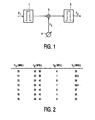
- the filter arrangement shown in FIG. 1 has as components a first bandpass filter 1, a second bandpass filter 2, a mixer 3 and a local oscillator 4.
- An input signal F 1 is applied to this filter arrangement and outputs an output signal F 2 .
- the aim of the arrangement is to vary the bandwidth f B and the center frequency f C of the output signal F 2 .
- the input signal F 1 is fed to the first bandpass filter 1, the output of which is connected via the mixer 3 to the input of the second bandpass filter 2.
- the mixer 3 is supplied with the output signal F 3 of the local oscillator 4 at a variable frequency. If the frequency of the local oscillator 4 is changed and the parameters of the two bandpass filters 1, 2 are left unchanged, the center frequency f C of the output signal F 2 changes .
Landscapes
- Superheterodyne Receivers (AREA)
- Input Circuits Of Receivers And Coupling Of Receivers And Audio Equipment (AREA)
Abstract
Description
Diese Anordnung zeichnet sich durch einen besonders einfachen Aufbau aus, da nur ein Mischer und zwei gleichartige Bandpassfilter benötigt werden.
- Figur 1
- den Aufbau der erfindungsgemäßen Filteranordnung und
- Figur 2
- eine Frequenztabelle der erfindungsgemäßen Filteranordnung.
Claims (4)
- Filteranordnung mit einem lokalen Oszillator (4), mit Bandpassfiltern (1, 2) und mit einem Mischer (3),
dadurch gekennzeichnet, dass zwei Bandpassfilter (1, 2) mit gleicher Bandbreite fB und Mittenfrequenz fC vorgesehen sind, wobei der Ausgang des ersten Bandpassfilters (1) mit dem Eingang des zweiten Bandpassfilters (2) mittels eines Mischers (3) gekoppelt ist und der lokale Oszillator (4) zur Steuerung des Mischers (3) vorgesehen ist. - Filteranordnung nach Anspruch 1,
dadurch gekennzeichnet, dass die Frequenz des Ausgangssignals (F3) des lokalen Oszillators (4) variabel ist und dass vorgesehen ist, durch die Veränderung der Frequenz des Ausgangssignals (F3) des lokalen Oszillators (4) die Bandbreite fB und die Mittenfrequenz fC des Ausgangssignals (F2) der Filteranordnung zu variieren. - Filteranordnung nach Anspruch 2,
dadurch gekennzeichnet, dass diese zur Wahl der Zwischenfrequenz bei Quadraturamplitudenmodulation vorgesehen ist. - Filteranordnung nach Anspruch 1,
dadurch gekennzeichnet, dass die Bandpassfilter (1, 2) eine feste Bandbreite fB aufweisen.
Applications Claiming Priority (2)
| Application Number | Priority Date | Filing Date | Title |
|---|---|---|---|
| DE10026161 | 2000-05-26 | ||
| DE10026161A DE10026161A1 (de) | 2000-05-26 | 2000-05-26 | Filteranordnung |
Publications (1)
| Publication Number | Publication Date |
|---|---|
| EP1158673A2 true EP1158673A2 (de) | 2001-11-28 |
Family
ID=7643683
Family Applications (1)
| Application Number | Title | Priority Date | Filing Date |
|---|---|---|---|
| EP01112025A Withdrawn EP1158673A2 (de) | 2000-05-26 | 2001-05-23 | Filteranordnung |
Country Status (5)
| Country | Link |
|---|---|
| US (1) | US20020044021A1 (de) |
| EP (1) | EP1158673A2 (de) |
| JP (1) | JP2002026757A (de) |
| KR (1) | KR20010107666A (de) |
| DE (1) | DE10026161A1 (de) |
Families Citing this family (3)
| Publication number | Priority date | Publication date | Assignee | Title |
|---|---|---|---|---|
| FR2849726B1 (fr) * | 2003-01-06 | 2005-02-25 | Thomson Licensing Sa | Dispositif de filtrage tres selectif et procede de filtrage correspondant |
| CN104205481B (zh) * | 2012-03-30 | 2016-06-08 | Ace技术株式会社 | 可变带宽rf滤波器 |
| US10523305B2 (en) * | 2017-05-11 | 2019-12-31 | Wilson Electronics, Llc | Variable channelized bandwidth booster |
Family Cites Families (1)
| Publication number | Priority date | Publication date | Assignee | Title |
|---|---|---|---|---|
| US5734090A (en) * | 1996-03-27 | 1998-03-31 | Alcohol Sensors International, Ltd. | Method and apparatus for sonic breath determination |
-
2000
- 2000-05-26 DE DE10026161A patent/DE10026161A1/de active Pending
-
2001
- 2001-05-22 US US09/862,283 patent/US20020044021A1/en not_active Abandoned
- 2001-05-23 EP EP01112025A patent/EP1158673A2/de not_active Withdrawn
- 2001-05-23 KR KR1020010028291A patent/KR20010107666A/ko not_active Withdrawn
- 2001-05-24 JP JP2001155295A patent/JP2002026757A/ja active Pending
Also Published As
| Publication number | Publication date |
|---|---|
| JP2002026757A (ja) | 2002-01-25 |
| KR20010107666A (ko) | 2001-12-07 |
| DE10026161A1 (de) | 2001-11-29 |
| US20020044021A1 (en) | 2002-04-18 |
Similar Documents
| Publication | Publication Date | Title |
|---|---|---|
| DE2257574B1 (de) | ||
| EP0198862B1 (de) | Verfahren und schaltungsanordnung zum umsetzen frequenzmodulierter signale über mindestens eine zwischenfrequenz in niederfrequenzsignale | |
| EP0818888B1 (de) | Umschaltbares Bandfilter für Mehrband-Tuner | |
| EP0195480B1 (de) | Schaltungsanordnung für einen Tuner zur Umschaltung zweier Frequenzbänder | |
| DE3821716A1 (de) | Fernsehtuner mit einer bandfilterschaltung | |
| DE102004057241A1 (de) | Doppelwandlungstuner | |
| WO2012095230A1 (de) | Hochfrequenzgenerator mit geringem phasenrauschen | |
| EP0258332B1 (de) | Verfahren und vorrichtung zur frequenzumsetzung frequenzmodulierter signale | |
| EP0696139B1 (de) | Verfahren und Schaltung zur Verarbeitung von digitalen und analogen Eingangssignalen | |
| EP1158673A2 (de) | Filteranordnung | |
| DE2624133C3 (de) | Mischeranordnung | |
| EP1128552B1 (de) | Schaltungsanordnung zur Filterung eines Hochfrequenzsignals | |
| DE10122830A1 (de) | Abwärts-Mischeinrichtung | |
| DE3240565A1 (de) | Direktmischender synchronempfaenger | |
| DE19728315A1 (de) | Fernsehsignal-Empfänger | |
| DE3606438C2 (de) | ||
| DE3538921C2 (de) | ||
| DE3246295C2 (de) | Frequenzmodulierbarer Oszillator | |
| DE2730153A1 (de) | Verfahren und vorrichtung zum empfangen von radiosignalen nach dem ueberlagerungsprinzip | |
| DE3346981A1 (de) | Ton-zf-verstaerker fuer einen mehrnormen-fernsprechempfaenger | |
| DE2816077C2 (de) | Frequenzgenerator | |
| DE4341221A1 (de) | Anordnung zur Verringerung von Störungen bei Schwingkreisen in integrierten Schaltungen | |
| DE10116886B4 (de) | Verfahren zum Optimieren des Frequenzaufbereitungszuges eines Hochfrequenz-Überlagerungsempfängers | |
| DE19921438B4 (de) | Überlagerungsstufe für Hochfrequenzempfänger | |
| EP0620656B1 (de) | Sender-/Empfängeranordnung für höhere Frequenzen |
Legal Events
| Date | Code | Title | Description |
|---|---|---|---|
| PUAI | Public reference made under article 153(3) epc to a published international application that has entered the european phase |
Free format text: ORIGINAL CODE: 0009012 |
|
| AK | Designated contracting states |
Kind code of ref document: A2 Designated state(s): AT BE CH CY DE DK ES FI FR GB GR IE IT LI LU MC NL PT SE TR |
|
| AX | Request for extension of the european patent |
Free format text: AL;LT;LV;MK;RO;SI |
|
| RAP1 | Party data changed (applicant data changed or rights of an application transferred) |
Owner name: PHILIPS CORPORATE INTELLECTUAL PROPERTY GMBH Owner name: KONINKLIJKE PHILIPS ELECTRONICS N.V. |
|
| RAP1 | Party data changed (applicant data changed or rights of an application transferred) |
Owner name: PHILIPS INTELLECTUAL PROPERTY & STANDARDS GMBH Owner name: KONINKLIJKE PHILIPS ELECTRONICS N.V. |
|
| STAA | Information on the status of an ep patent application or granted ep patent |
Free format text: STATUS: THE APPLICATION HAS BEEN WITHDRAWN |
|
| 18W | Application withdrawn |
Effective date: 20040422 |