EP1158665A2 - Verstärker mit mehreren Eingängen mit einer Anzahl von Verstärkelementen unterschiedlich von 2n - Google Patents
Verstärker mit mehreren Eingängen mit einer Anzahl von Verstärkelementen unterschiedlich von 2n Download PDFInfo
- Publication number
- EP1158665A2 EP1158665A2 EP01850048A EP01850048A EP1158665A2 EP 1158665 A2 EP1158665 A2 EP 1158665A2 EP 01850048 A EP01850048 A EP 01850048A EP 01850048 A EP01850048 A EP 01850048A EP 1158665 A2 EP1158665 A2 EP 1158665A2
- Authority
- EP
- European Patent Office
- Prior art keywords
- input
- amplifiers
- output
- hybrid
- amplifier
- Prior art date
- Legal status (The legal status is an assumption and is not a legal conclusion. Google has not performed a legal analysis and makes no representation as to the accuracy of the status listed.)
- Withdrawn
Links
Images


Classifications
-
- H—ELECTRICITY
- H03—ELECTRONIC CIRCUITRY
- H03F—AMPLIFIERS
- H03F3/00—Amplifiers with only discharge tubes or only semiconductor devices as amplifying elements
- H03F3/60—Amplifiers in which coupling networks have distributed constants, e.g. with waveguide resonators
- H03F3/602—Combinations of several amplifiers
-
- H—ELECTRICITY
- H03—ELECTRONIC CIRCUITRY
- H03F—AMPLIFIERS
- H03F3/00—Amplifiers with only discharge tubes or only semiconductor devices as amplifying elements
- H03F3/68—Combinations of amplifiers, e.g. multi-channel amplifiers for stereophonics
Definitions
- This invention relates to paralleled amplifiers, and more particularly to paralleled amplifiers interconnected by hybrids to provide channelization, where the number of amplifiers in the paralleled arrangement can be other than 2 N , where N is an integer.
- Multichannel spacecraft communications systems are now widely used.
- Electronic amplifiers are used to boost signal strength at each end of an uplink and downlink.
- Power amplifiers are used to boost the power of the signal at the spacecraft before retransmission to earth.
- Amplifiers are basically nonlinear. If a single power amplifier were to be used to boost the signal power for all of a plurality of channels, the signals in the plural channels would become jumbled together, and, in addition to intermodulation problems attributable to the nonlinearity, the additional problem would exist that the signals could not be re-separated into separate channels without the use of frequency-sensitive filters.
- phase-sensitive hybrid combining networks are coupled to the inputs of the amplifiers, and corresponding phase-sensitive separation hybrid networks are coupled to the outputs of the amplifiers to separate the amplified signals into the original channels.
- each separate channel appearing at the output of the phase-sensitive separation network may be designated, for example, for transmission over a separate antenna beam to a different portion of the Earth's surface.
- FIGURE1a is a simplified block diagram of a spacecraft communication system 10 using a prior-art paralleled amplifier.
- communication system 10 includes a spacecraft 12 and first and second ground stations 14 and 16, respectively.
- the spacecraft 12 is illustrated as including a receiving antenna 12ar and a transmitting antenna 12at.
- Receiving antenna 12ar forms two separate receive antenna beams, designated 12rb1 and 12rb2, directed toward ground stations 14 and 16, respectively.
- the signals from ground station 14 are generated at a beamformer output port 12arol, and the signals from ground station 16 are generated at a beamformer output port 12aro2. These signals are designated A and B, for ease of notation.
- the A signals are transmitted from ground station 14 to receive antenna 12r by way of beam 12rb1, and the B signals are transmitted from ground station 16 by way of beam 12rb2.
- the A and B signals are amplified in a paralleled amplifier 20 for application to beamformer ports 12ati2 and 12ati1, respectively, of transmitting antenna 12at of spacecraft 12.
- Paralleled amplifier 20 has first and second input ports 20i1 and 20i2, and first and second output ports 20o1 and 20o2.
- the A signals applied to input port 12ati2 are transmitted to ground station 16 by way of antenna beam 12atb2, and the B signals applied to input port 12atil are transmitted to ground station 14 by way of beam 12tb1. Consequently, in the simple system of FIGURE 1a, two separate locations on the Earth can communicate by way of pairs of antenna beams.
- the A and B signals may be viewed as being channels of information.
- the "paralleled" aspect of the amplifier 20 requires that there be some kind of cross-coupling of the A signals to amplifiers 1 and 2, and of the B signals to amplifiers 1 and 2.
- this cross-coupling is provided by hybrids.
- ports 20i1 and 20i2 are coupled to the ports of a three-dB hybrid H1, well known in the art.
- Such hybrids are represented by crossed transmission lines in the form of the letter X, with the crossing representing the coupling between two transmission lines of the hybrid.
- the ports of hybrid H1 of FIGURE 1a are designated H1 1 , H1 2 , H1 3 , and H1 4 , with ports H1 1 and H1 2 being equivalent to, or contiguous with, parallel amplifier ports 20i1 and 20i2, respectively.
- a transmission line illustrated as a line designated T1
- another transmission line illustrated as a line designated T2
- a salient characteristic of such hybrids is that, over a significant frequency band, the input signals applied to port H1 1 appear at ports H1 3 and H1 4 with 1/2 power, and in mutual phase quadrature, and port H1 2 is isolated from port H1 1 . Similarly, signals applied to port H1 2 appear at ports H1 3 and H1 4 with 1/2 power, and in mutual phase quadrature.
- FIGURE 1b illustrates a common way to designate these characteristics.
- the signal at port H1 1 is designated as (1,0), representing full power and a reference phase of 0°.
- the signal at port H1 2 resulting from application of (1,0) to port H1 1 is (0,0) representing zero power or no signal.
- the signals appearing at ports H1 3 and H1 4 as a result of application of signal (1,0) to port H1 1 are designated as (1 ⁇ 2, 90) and (1 ⁇ 2, 0), representing half-amplitude or half-power, with mutually quadrature phase shifts of 90° and 0° respectively.
- the terms "input” and "output” as applied to the ports of a hybrid refer only to its application, since the device is linear.
- a port termed an "input” port in one application may well be an "output” port in another application, or even in a different mode of operation of the same application.
- amplifier 1 receives for amplification the sum of (A/2,90) and (B/2,0), while amplifier 2 receives (A/2,0) and (B/2,90).
- These signals which may be designated (A/2,90)+(B/2,0) and (A/2,0)+(B/2,90), respectively, appear in amplified form at the outputs of amplifiers 1 and 2 in the usual manner. While the amplifiers may invert phase, the amplification and phase inversion are not relevant to the end result, and are ignored in the discussion.
- Amplified summed signal (A/2,90)+(B/2,0) appears at the output of amplifier 1 for application to an input port H2 1 of a 3dB hybrid H2, and amplified summed signal (A/2,0)+(B/2,90) appears at the output of amplifier 2 for application to input port H2 2 of hybrid H2.
- Hybrid H2 performs the same kind of operation as hybrid H1, and more particularly couples amplified summed signal (A/2,90)+(B/2,0) from port H2 1 to port H2 3 at half power and with a relative 90° phase shift, and couples amplified summed signal (A/2,0)+(B/2,90) from port H2 2 to port H2 3 at half power and with a 0° relative phase.
- hybrid H2 couples amplified summed signal (A/2,90) + (B/2,0) from port H2 1 to port H2 4 with half-amplitude and relative phase of 0°, and couples amplified summed signal (A/2,0)+(B/2,90) applied to port H2 2 to port H2 4 with half-amplitude and a phase of 90°.
- the sum signal appearing at port H2 3 is (A/4,180)+(B/4,90)+(A/4,0)+(B/4,90), and the sum signal appearing at port H2 4 is (A/4,90)+(B/4,0)+(A/4,90)+(B/4,180).
- The(B/4,0) and (B/4,180) components appearing at port H2 4 also cancel, leaving (A/4,90)+(A/4,90),which is equivalent to (A,90).
- the phase sensitivity of the hybrids at the input and output ports of amplifiers 1 and 2 allow each amplifier to amplify components of the input signals, but also allow separation or channelization of the signals following (downstream from) the parallel amplification.
- the output ports H2 3 and H2 4 of hybrid H2 are contiguous with output ports 20o1 and 20o2, respectively, of paralleled amplifier 20.
- the arrangement of paralleling amplifiers as described in conjunction with FIGURES 1a and 1b has a salient advantage over simple use of two independent amplifiers.
- the peak amplitude portions of two independent signals will not occur simultaneously, and thus the full output power capacity of each individual amplifier is used only a small portion of the time.
- This fact may be taken advantage of in a paralleled amplifier arrangement to allow the signals to be amplified to higher levels than in separate-single-amplifier arrangement. This is because the paralleled amplifiers can "apply” or "use” some of the capacity not used by the momentarily lower-level signals to accommodate that signal which is momentarily at a higher level.
- EIRP Effective Isotropic Radiated Power
- a paralleled amplifier 220 includes four amplifiers organized as two paralleled amplifiers 20, identical to those described in conjunction with FIGURE 1a. To distinguish between the two paralleled amplifiers 20 of FIGURE 2a, they are designated 20 1 and 20 2 .
- the input ports of the paralleled amplifier 20 1 are designated 20i 1,1 and 20i 2,1
- the input ports of paralleled amplifiers 20 2 are designated 20i 1,2 and 20i 2,2 .
- each of paralleled amplifiers 20 1 and 20 2 of FIGURE 2a the input hybrid, designated H1 in FIGURE 1a, is redesignated as 31, and the output hybrid, H2 in FIGURE 1a, is redesignated 32.
- Each of the paralleled amplifiers 20 1 and 20 2 may be viewed as being equivalent to a single amplifier 1 or 2 of FIGURE 1a, requiring only some sort of cross-coupling to get A and B signals to paralleled amplifier 20 2 , and to get the C and D signals to paralleled amplifier 20 1 .
- the A signals applied to paralleled amplifier 220 of FIGURE 2a are coupled to input port 1 of a 3dB hybrid 230, and the B input signals are applied to its input port 2.
- the C input signals to paralleled amplifier 220 are applied to input port 1 of a 3dB hybrid 232, and the D input signal is applied to its input port 2.
- Output port 3 of hybrid 230 is coupled to input port 20i 11 of paralleled amplifier 20 1
- output port 4 of hybrid 232 is coupled to input port 20i 22 of paralleled amplifier 20 2 .
- Cross-coupling is provided by connecting, output port 4 of hybrid 230 to input port 20i 12 of paralleled amplifier 20 2
- output port 3 of hybrid 232 is coupled to input port 20i 21 of paralleled amplifier 20 1 .
- output port 20o1 of paralleled amplifier 20 1 is coupled to port 1 of a 3dB hybrid 234, and output port 20o2 of paralleled amplifier 20 2 is coupled to input port 2 of hybrid 236.
- Output port 20o2 of paralleled amplifier 20 1 is coupled to port 1 of a 3dB hybrid 236, and output port 20o1 of paralleled amplifier 20 2 is coupled to input port 2 of hybrid 234.
- the A output is produced at port 4 of hybrid 236, the B signal is produced at output port 3 of hybrid 236, the C signal is produced at output port 4 of hybrid 234, and the D signal is produced at output port 3 of hybrid 234.
- the output signals appear at the "opposite" output port from the port at which they entered, and thus signal A enters at the "top” of the structure, and exits at the "bottom,” while signal D enters at the "bottom” and exits at the "top.”
- the paralleled amplifiers four watts, for the case of one-watt amplifiers
- FIGURE 2b represents the arrangement of FIGURE 2a in a skeletonized form, with the amplifiers redesignated as amplifiers 1, 2, 3, and 4, and with the hybrids undesignated.
- the input and output ports of the paralleled amplifier arrangement of FIGURE 2b are designated by the signal or channel designation, namely A, B, C, and D.
- the representation of FIGURE 2b is easier to understand than that of FIGURE 2a since it is less "busy.”
- FIGURE 3 illustrates an eight-channel arrangement including the parallel combination of eight amplifiers.
- amplifiers 1, 2, 3, and 4 may be viewed as part of a four-paralleled amplifier arrangement 320 1 , similar to the arrangement of 220 of FIGURES 2a and 2b, and amplifiers 5, 6, 7, and 8 may be viewed as part of a four-paralleled-amplifier arrangement 320 2 , also similar to the arrangement 220.
- paralleled amplifiers 320 1 and 320 2 are cross-coupled by a set 330 of hybrids, including hybrids 330AB, 330CD, 330EF, and 330GH.
- Hybrid 330AB couples signals A and B from input terminals at the left of FIGURE 3 to paralleled amplifier 320 1
- hybrid 330cd couples signals C and D from correspondingly designated input terminals to paralleled amplifier 320 1 .
- Hybrid 330EF couples signals E and F to paralleled amplifier 320 1
- hybrid 330GH couples signals G and H to paralleled amplifier 320 1 .
- hybrid 330AB couples signals A and B to paralleled amplifier 320 2
- hybrid 330cd couples C and D to paralleled amplifier 20 2
- Hybrid 330EF couples signals E and F to paralleled amplifier 320 2
- hybrid 330GH couples signals G and H to paralleled amplifier 320 2
- another set 340 of hybrids namely hybrids 340GH, 340EF, 340CD, and 340AB, provides corresponding phase-sensitive cross-coupling which results in separation of the A, B, C, D, and E signals at the correspondingly designated output terminals at the right of FIGURE 3.
- This scheme also has an EIRP flexibility of 100%.
- the arrangement of FIGURE 3 corresponds to that described in U.S. Patent 4,618,831, issued October 21, 1986 in the name of Egami et al.
- travelling-wave tube amplifiers may not be available for the desired power levels if particular numbers of amplifiers are used; if the system specifies ten channels with an output power of one watt per channel, the use of ten amplifiers requires one-watt amplifiers, which may be available, but the use of sixteen amplifiers requires 620-milliwatt amplifiers, which may not be available. In most applications, the disadvantages of a system with supernumerary channels preclude its use.
- the intermodulation distortion of paralleled-amplifier arrangements relative to the prior art single-amplifier-per-channel scheme depends at least in part on the traffic or signal loading.
- Single frequency modulated television signals (FMTV) and single time-division multiplex (TDMA) signals tend to have lower cross-modulation and intermodulation when amplified in separate amplifiers than in paralleled amplifiers, while traffic including multiple carriers, as in mobile applications (where each beam is treated as a separate channel) provide the same performance in both the separate-amplifier and paralleled-amplifier schemes.
- FIGURE 4 is a simplified block diagram of a ten-channel paralleled-amplifier 420 such as might be used in the prior art in a ten-channel communication system.
- portion 320 is similar to the eight-channel amplifier of FIGURE 3, and its separate portions are not designated individually.
- eight-paralleled amplifier 420 handles channels or signals designated A, B, C, D, E, F, G, and H.
- a two-amplifier paralleled arrangement 420 similar to 20 of FIGURE 1 is provided for handling channels or signals I and J. This arrangement is functional, and has the advantage of providing but a single amplifier for each channel, but suffers from the disadvantage that the EIRP flexibility is no longer 100%.
- the total system power (for one-watt amplifiers) is ten watts, but signals in the two-amplifier portion 420 can have a maximum output level of two watts, which corresponds to an EIRP flexibility of 20%, and the corresponding EIRP flexibility of eight-amplifier portion 320 is 8 watts out of ten, or 80%.
- signals applied to input ports I and J can draw power from only two amplifiers, rather than be capable of drawing power from eight amplifiers, as with signals applied to input ports A through H.
- a paralleled amplifier arrangement includes an amplifier set including a plurality of amplifiers. Each of the amplifiers of the amplifier set includes an input port and an output port.
- the number of the amplifiers in the amplifier set associated with the paralleled amplifier arrangement is an even number M which is not an integer power of two.
- the paralleled amplifier arrangement includes a plurality of input ports, equal in number to the number of input ports associated with the amplifier set.
- the paralleled amplifier arrangement also includes a plurality of output ports, equal in number to the plurality of output ports of the amplifier set.
- the paralleled amplifier arrangement includes an input combining arrangement including a number ⁇ (M/2) int(log 2 M) ⁇ of input hybrids, connected in such a manner that a signal applied to any one of the input ports of the paralleled amplifier arrangement passes through the same number of the paralleled amplifiers as a signal applied to any other input port.
- the paralleled amplifier arrangement further includes an output combining arrangement coupled to the output ports of the plurality of amplifiers, and to the output ports of the paralleled amplifier arrangement.
- the output combining arrangement includes a plurality of output hybrids, equal in number to the number of input hybrids in the input combining arrangement, connected in a mirror-image manner relative to the connections of the input hybrids.
- FIGURE 5a illustrates a conventional hybrid, such as those described in conjunction with FIGURES 1b and 2a, with the port numbering as in FIGURE 2b, namely with "input” ports 1 and 2, and “output” ports 3 and 4.
- each port 1, 2, 3, or 4 can be an input port, and that the distribution of power from the input port to the other ports depends upon the configuration of the hybrid.
- FIGURE 5b represents the symbol which is used to represent the conventional hybrid of FIGURE 5a hereinafter. Basically, the representation is that of a box with the letter “O,” which refers to the word "output.”
- the output hybrids are used in the output combining network of a paralleled amplifier in accordance with an aspect of the invention.
- FIGURE 5c represents a conventional hybrid, in which the connections of the "input" ports 1 and 2 of the hybrid are reversed relative to those of FIGURE 5a.
- FIGURE 5d represents the symbol which is used to represent the reversed-connection hybrid of FIGURE 5c.
- the representation is basically of a box with the identifying letter I, representing the word "input,” referring to the use of such reversed-connection hybrids at the input dividing network of a paralleled amplifier according to an aspect of the invention.
- FIGURE 5a also illustrates, adjacent each port of the hybrid, the relative power and phase, in the format (P, ), assuming that a signal of 1 watt, 0° is applied to port 1.
- FIGURE 6a is a simplified representation of a paralleled amplifier arrangement 510 according to an aspect of the invention, in which a set 512 of ten amplifiers are paralleled.
- the ten amplifiers of set 512 is arrayed in the direction of an axis or plane 8, and each of the amplifiers 1, 2, 3, 4, 5, 6, 7, 8, 9, 10 of the paralleled amplifier arrangement 510 has a single input port (at its left side or at the broad side of the amplifier symbol) and a single output port (on the right side or at the pointed end of the amplifier symbol) available for signal flow.
- paralleled amplifier arrangement 510 input ports A, B, C, D, E, F, G, H, I and J are coupled to the input ports of amplifiers 1, 2, 3, 4, 5, 6, 7, 8, 9, 10 by an input network (INET) 514.
- INET input network
- FIGURE 6b illustrates details of INET 514 of FIGURE 6a
- FIGURE 6c illustrates details of ONET 516
- the hybrids of the input network are all of the input (I) type.
- the paralleled amplifier arrangement 510 includes ten output ports, designated as A', B', C', D', E', F', G', H', I', and J'.
- the set 512 of ten amplifiers 1, 2, 3, 4, 5, 6, 7, 8, 9, 10 is coupled to the set of output ports A', B', C', D', E', F', G', H', I' and J' by a output network (ONET) 516.
- ONET 516 includes a set 516 of "output" (O) hybrids. The number of hybrids in output set 516 equals the number of hybrids in the input hybrid set 514.
- the input hybrids are illustrated as being arrayed in three columns and five rows, where the column numbering starts at the row most remote from the paralleled amplifier set 512.
- the column numbering starts at the column marked "col. 1".
- the designations of the input hybrids of FIGURE 6b are given by the numeral 514 CR , where C represents the column, and R the row.
- the input hybrids of the first column of set 514 are designated 514 11 , 514 12 , 514 13 , 514 14 , and 514 15 .
- each input hybrid of set 514 of FIGURE 6b has ports denominated in the same manner as those of FIGURES 5c and 5d, namely by the numerals 1, 2, 3, and 4.
- the port designations are only provided for input hybrids 514 11 , 514 13 , 514 15 , 514 22 , 514 24 , 514 31 , 514 33 , and 514 35 .
- the output hybrids are illustrated as being arrayed in three columns and five rows, where the column numbering starts at the column most remote from the paralleled amplifier set 512, which is the column marked "col.1".
- the designations of the output hybrids are given by the numeral 516 CR , where C represents the column, and R the row.
- the output hybrids of the first column of set 516 are designated 516 11 , 516 12 , 516 13 , 516 14 , and 516 15 .
- each output hybrid of set 516 of FIGURE 6c has ports denominated in the same manner as those of FIGURES 5a and 5b, namely by the numerals 1, 2, 3, and 4. For simplicity, the port designations are only provided for output hybrids 516 11 , 516 13 , 516 15 , 516 22 , 516 24 , 516 31 , 516 33 , and 516 35 .
- the input ports 1 and 2 of each hybrid of column 1 of INET 514 of FIGURE 6b are connected to a corresponding pair of input ports of paralleled amplifier arrangement 510 of FIGURE 6. More particularly, input ports 1 and 2 of hybrid 514 11 are connected to paralleled amplifier input ports A and B, respectively. Similarly, input ports 1 and 2 of hybrid 514 12 are connected to paralleled amplifier input ports C and D, respectively, input ports 1 and 2 of hybrid 514 13 are connected to paralleled amplifier input ports E and F, respectively, input ports 1 and 2 of hybrid 514 14 are connected to paralleled amplifier input ports G and H, respectively, and input ports 1 and 2 of hybrid 514 15 are connected to paralleled amplifier input ports I and J, respectively.
- output ports 1 and 2 of hybrid 516 11 of ONET 516 of FIGURE 6c are connected to paralleled amplifier output ports A' and B', respectively.
- output ports 1 and 2 of hybrid 516 12 are connected to paralleled amplifier input ports C' and D', respectively
- output ports 1 and 2 of hybrid 516 13 are connected to paralleled amplifier output ports E' and F', respectively
- output ports 1 and 2 of hybrid 516 14 are connected to paralleled amplifier output ports G' and H', respectively
- output ports 1 and 2 of hybrid 516 15 are connected to paralleled amplifier output ports I' and J', respectively.
- the signal output of the j th port of the i th hybrid in the k th column be O k [i,j], and its signal input I k [i,j].
- j can be either 1 or 2, corresponding to the numbering of the input port, i varies from 1 to (M/2), and k varies from 1 to log 2 M'.
- M 10
- i can vary from 1 to 5
- k can vary from 1 to 3.
- I k [i,j] O k-1 [int(((i-1)+(j-1)M/2)/2)+1, (i-1+(j-1)M/2) mod 2+1] for:
- equation (5) which means that the first input port (the port designated 1) of the hybrid 514 21 in the first row, second column is connected to the first output port (the port designated 3) of the hybrid 514 11 in the first row of the first column. This connection is designated 518 1 in FIGURE 6b.
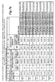
- the calculation steps are set forth in summary form in the corresponding row (Hybrid #1, Port #1) of the table of FIGURE 7a.
- I 2 [1,2] O 1 [int((1-1 + 10/2)/2)+1, (1-1+10/2) mod 2 + 1]
- I 2 [1,2] O 1 [int(5/2), 1+1]
- I 2 [1,2] O 1 [int(2.5)+1, 2]
- I 2 [1,2] O 1 [3, 2]
- I 2 refers to an input port of a hybrid of the second column
- the first "1" in "[1,2]" refers to a hybrid in the first row
- the "2" refers to the second input port.
- equation (9) means that the second input port (port designated 2) of the hybrid 514 21 occupying the location in the first row, second column, is connected to the second output port (port designated 4) of that hybrid 514 13 in the third row of the first column, third row.
- This connection is designated 518 2 in FIGURE 6b, and the steps of the determination are set forth in the second row (Hybrid # 1, Port # 2) of the table of FIGURE 7a.
- the output connections for the hybrid 514 21 of FIGURE 6b are determined by the connections to the input ports, using equations (2) and (3), applied to the hybrids of the third column.
- equation (1) determines the connections of an input hybrid
- I k [i,1] O k-1 [int((i-1)/2)+1, (i-1) mod 2 + 1]
- I 2 [3,1] O 1 [2,1] which indicates that the input port in question in the second column, in the hybrid in the third row, and the first port, is connected to an output port in the first column, and in that first column, the output port is one in the second row, it is the first output port (port designated 3 of hybrid 514 12 .
- This connection is designated 518 5 .
- connections for any one of the hybrids in the input combining network of FIGURE 6b can be determined by recourse to equations (2) and (3), or alternatively from the table of FIGURE 7a.
- the connections of the output combining network 516 of FIGURE 6c can be found from equations (2) and (3) by redesignating the columns to begin at column 1 with the last column, and the ports of the hybrids are also redesignated, as shown in FIGURE 6c.
- the row designations remain the same as for the input combining network.
- the hybrids of the output combining network 516 are of the O or output type described in conjunction with FIGURES 5a and 5b.
- FIGURE 7a applies only to the case of ten amplifiers in the paralleled amplifier arrangement, the equations can be used for any even number of amplifiers which do not necessarily equal a power of two.
- a table corresponding to that of FIGURE 7a can be generated from the equations for any such number of amplifiers.
- the table of FIGURE 7b applies to a twelve-amplifier paralleling arrangement.
- the structure of FIGURE 7c simply illustrates two mutually adjacent columns of hybrids to indicate the applicability of the tables of FIGURES 7a and 7b.
- FIGURE 6a, b and c differs functionally from the prior-art arrangement of FIGURE 4. It will be noted that in the arrangement of FIGURE 4, the signals applied to input ports A, B, C, D, E, F, G, and H are divided into eight parts, which flow in equal amounts or with equal magnitudes through each of amplifiers 1, 2, 3, 4, 5, 6, 7, and 8, respectively, but the signals applied to input ports I and J are divided into two parts, to flow through amplifiers 9 and 10. Thus, some of the signals (those applied to ports A through H) each flow (in parallel) through eight amplifiers, while other signals (those applied to ports I and J) flow through only two amplifiers.
- the signals applied to any one of input ports A through J are divided eight times, and flow in equal amplitudes through eight of the ten amplifiers.
- No signal applied to an input port of the arrangement of FIGURE 6b flows through less than eight amplifiers. This provides improved redundancy for at least some of the signals above that of the prior art, in addition to an improvement in EIRP flexibility to 100%.
- FIGURE 8 is a simplified diagram of another embodiment of the invention including a paralleled amplifier arrangement 810 using a set 512 of ten amplifiers paralleled by the use of an input hybrid arrangement 814 and an output hybrid arrangement 816.
- the input hybrid arrangement 814 differs from input hybrid arrangement 514 described in conjunction with FIGURE 6, and the output hybrid arrangement 816 is the mirror image of input hybrid arrangement 814, and consequently also differs from output hybrid arrangement 516 of FIGURE 6.
- simplified connections are provided between the first and second columns.
- I 2 [M/2,2] O 1 [1,1]
- FIGURE 9 is a simplified diagram of another embodiment of the invention including a paralleled amplifier arrangement m10 using a set 512 of ten amplifiers paralleled by the use of an input hybrid arrangement 914 and an output hybrid arrangement 916.
- the input hybrid arrangement 914 differs from input hybrid arrangement 514 described in conjunction with FIGURE 6, and the output hybrid arrangement 916 is the mirror image of input hybrid arrangement 914, and consequently also differs from output hybrid arrangement 516 of FIGURE 6.
- the invention solves the problems of (a) how to connect the M' columns so that maximum division of the signal is obtained when the signals arrive at the set of individual amplifiers, (b) how to assure that all M individual amplifiers are equally used, so that the full RF power is realized when all M signals are present, even if M is not a power of 2, and (c) how to assure that the signals "add up” correctly (add in proper phase and amplitude) at the output of the paralleled amplifier arrangement.
- a paralleled amplifier arrangement (510, 810, 910) includes a set (512) of amplifiers, which includes a plurality of individual amplifiers (1, 2, 3, 4, 5, 6, 7, 8, 9, 10). Each of the amplifiers of the set (512) includes an input port and an output port.
- the number of the amplifiers in the set of amplifiers associated with the paralleled amplifier arrangement (510), according to the invention, is an even number (10 in FIGURES 6a, 6b, 6c , 8, and 9) which is not an integer power of two.
- the paralleled amplifier arrangement (510, 810, 910) includes a plurality M of input ports (A through J), equal in number to the number of input ports associated with the set (512) of amplifiers.
- the paralleled amplifier arrangement (510, 810, 910) also includes a plurality of output ports (A' through J'), equal in number to the plurality of output ports of the set (512) of amplifiers.
- an "input" hybrid is similar to a conventional or “output” hybrid, but has reversed input ports.
- the paralleled amplifier arrangement (510, 810, 910) further includes an output combining arrangement (516, 816, 916) coupled to the output ports of the set (512) of a plurality of amplifiers, and to the output ports (A' through J') of the paralleled amplifier arrangement (510, 810, 910).
- the output combining arrangement (516, 816, 916) includes a plurality of output hybrids (O), equal in number to the number of input (I) hybrids in the input combining arrangement (514, 814, 914), connected in a mirror-image manner relative to the connections of the input hybrids.
- connections of the output hybrid arrangement (516, 816, 916), when "folded” along a line (8) associated with the array of the set (512) of amplifiers, is congruent with the connections of the input hybrid arrangement (514, 814, 914).
Applications Claiming Priority (2)
| Application Number | Priority Date | Filing Date | Title |
|---|---|---|---|
| US528625 | 1990-05-24 | ||
| US09/528,625 US6437642B1 (en) | 2000-03-20 | 2000-03-20 | Multiport amplifier with a number of amplifier elements other than 2 |
Publications (2)
| Publication Number | Publication Date |
|---|---|
| EP1158665A2 true EP1158665A2 (de) | 2001-11-28 |
| EP1158665A3 EP1158665A3 (de) | 2004-02-11 |
Family
ID=24106468
Family Applications (1)
| Application Number | Title | Priority Date | Filing Date |
|---|---|---|---|
| EP01850048A Withdrawn EP1158665A3 (de) | 2000-03-20 | 2001-03-15 | Verstärker mit mehreren Eingängen mit einer Anzahl von Verstärkelementen unterschiedlich von 2n |
Country Status (2)
| Country | Link |
|---|---|
| US (1) | US6437642B1 (de) |
| EP (1) | EP1158665A3 (de) |
Families Citing this family (5)
| Publication number | Priority date | Publication date | Assignee | Title |
|---|---|---|---|---|
| US7088173B1 (en) | 2004-05-07 | 2006-08-08 | Lockheed Martin Corporation | Adjustable multiport power/phase method and system with minimum phase error |
| WO2008135754A1 (en) * | 2007-05-04 | 2008-11-13 | Astrium Limited | Tuning multiport amplifiers |
| GB0708721D0 (en) * | 2007-05-04 | 2007-06-13 | Astrium Ltd | Tuning multiport amplifiers |
| US9319000B2 (en) | 2013-07-31 | 2016-04-19 | The Boeing Company | Method and apparatus for improving leakage performance of a multi-port amplifier |
| US10624051B2 (en) | 2015-07-02 | 2020-04-14 | The Boeing Company | System for measuring multi-port amplifier errors |
Citations (1)
| Publication number | Priority date | Publication date | Assignee | Title |
|---|---|---|---|---|
| US5917371A (en) * | 1997-07-29 | 1999-06-29 | Metawave Communications Corporation | Signal feed matrix amplifier reduction system and method |
Family Cites Families (2)
| Publication number | Priority date | Publication date | Assignee | Title |
|---|---|---|---|---|
| JPS6178213A (ja) * | 1984-09-25 | 1986-04-21 | Nippon Telegr & Teleph Corp <Ntt> | 電力増幅装置 |
| US4644301A (en) * | 1985-10-31 | 1987-02-17 | Rca Corporation | Redundancy system and switching network |
-
2000
- 2000-03-20 US US09/528,625 patent/US6437642B1/en not_active Expired - Lifetime
-
2001
- 2001-03-15 EP EP01850048A patent/EP1158665A3/de not_active Withdrawn
Patent Citations (1)
| Publication number | Priority date | Publication date | Assignee | Title |
|---|---|---|---|---|
| US5917371A (en) * | 1997-07-29 | 1999-06-29 | Metawave Communications Corporation | Signal feed matrix amplifier reduction system and method |
Non-Patent Citations (1)
| Title |
|---|
| GIPPRICH J ET AL: "A compact 8-14 GHz LTCC stripline coupler network for high efficiency power combining with better than 82% combining efficiency" MICROWAVE SYMPOSIUM DIGEST, 1995., IEEE MTT-S INTERNATIONAL ORLANDO, FL, USA 16-20 MAY 1995, NEW YORK, NY, USA,IEEE, US, 16 May 1995 (1995-05-16), pages 1583-1586, XP010612620 ISBN: 0-7803-2581-8 * |
Also Published As
| Publication number | Publication date |
|---|---|
| EP1158665A3 (de) | 2004-02-11 |
| US6437642B1 (en) | 2002-08-20 |
Similar Documents
| Publication | Publication Date | Title |
|---|---|---|
| US6340948B1 (en) | Antenna system | |
| US9264114B2 (en) | Antenna device for a radio base station in a cellular telephony system | |
| US5809398A (en) | Channel selective repeater | |
| US20180226982A1 (en) | Broadband Digital Beam Forming System including Wavefront Multiplexers and Narrowband Digital Beam Forming Modules | |
| US5751250A (en) | Low distortion power sharing amplifier network | |
| EP1776777B1 (de) | Verfahren und sender mit einer antenne und symmetrischer verstärkerarchitektur zur bereitstellung von leistungsverstärker-lastausgleich unabhängig von einzel- oder doppelsignalbetrieb des senders | |
| US3917998A (en) | Butler matrix transponder | |
| US20120319885A1 (en) | System for processing data streams | |
| EP0756431A2 (de) | Leistungsverteiltes lineares Verstärkernetzwerk | |
| JPS6178213A (ja) | 電力増幅装置 | |
| US6381212B1 (en) | Power sharing amplifier system for amplifying multiple input signals with shared power amplifiers | |
| US5033108A (en) | Signal repeater using shared amplification with selectable input/output connections | |
| JP5138768B2 (ja) | マルチポート増幅器の調整 | |
| US8248977B2 (en) | Routing of downlink channels in a communications satellite | |
| US6437642B1 (en) | Multiport amplifier with a number of amplifier elements other than 2 | |
| US7019710B1 (en) | Antenna system | |
| JP2002299921A (ja) | 2n以外の数の増幅器要素を備えた多重ポート増幅器 | |
| GB2279504A (en) | Antenna system | |
| US6034969A (en) | Method and system for cross frame transmit combining of transmit signals | |
| Yamamoto et al. | High output port isolation and low intermodulation distortion multi-port-amplifier | |
| JP2000124819A (ja) | 無線信号送受信装置および増幅回路 | |
| JPS6374329A (ja) | 無線中継装置 |
Legal Events
| Date | Code | Title | Description |
|---|---|---|---|
| PUAI | Public reference made under article 153(3) epc to a published international application that has entered the european phase |
Free format text: ORIGINAL CODE: 0009012 |
|
| AK | Designated contracting states |
Kind code of ref document: A2 Designated state(s): AT BE CH CY DE DK ES FI FR GB GR IE IT LI LU MC NL PT SE TR |
|
| AX | Request for extension of the european patent |
Free format text: AL;LT;LV;MK;RO;SI |
|
| PUAL | Search report despatched |
Free format text: ORIGINAL CODE: 0009013 |
|
| AK | Designated contracting states |
Kind code of ref document: A3 Designated state(s): AT BE CH CY DE DK ES FI FR GB GR IE IT LI LU MC NL PT SE TR |
|
| AX | Request for extension of the european patent |
Extension state: AL LT LV MK RO SI |
|
| 17P | Request for examination filed |
Effective date: 20040719 |
|
| AKX | Designation fees paid |
Designated state(s): AT BE CH CY DE DK ES FI FR GB GR IE IT LI LU MC NL PT SE TR |
|
| 17Q | First examination report despatched |
Effective date: 20050527 |
|
| STAA | Information on the status of an ep patent application or granted ep patent |
Free format text: STATUS: THE APPLICATION IS DEEMED TO BE WITHDRAWN |
|
| 18D | Application deemed to be withdrawn |
Effective date: 20051007 |