EP1157944A2 - Récipient pour produits à un ou deux composants avec tube de distribution - Google Patents
Récipient pour produits à un ou deux composants avec tube de distribution Download PDFInfo
- Publication number
- EP1157944A2 EP1157944A2 EP01112455A EP01112455A EP1157944A2 EP 1157944 A2 EP1157944 A2 EP 1157944A2 EP 01112455 A EP01112455 A EP 01112455A EP 01112455 A EP01112455 A EP 01112455A EP 1157944 A2 EP1157944 A2 EP 1157944A2
- Authority
- EP
- European Patent Office
- Prior art keywords
- dispensing
- dispensing spout
- spout
- component
- particular according
- Prior art date
- Legal status (The legal status is an assumption and is not a legal conclusion. Google has not performed a legal analysis and makes no representation as to the accuracy of the status listed.)
- Granted
Links
Images


Classifications
-
- B—PERFORMING OPERATIONS; TRANSPORTING
- B65—CONVEYING; PACKING; STORING; HANDLING THIN OR FILAMENTARY MATERIAL
- B65D—CONTAINERS FOR STORAGE OR TRANSPORT OF ARTICLES OR MATERIALS, e.g. BAGS, BARRELS, BOTTLES, BOXES, CANS, CARTONS, CRATES, DRUMS, JARS, TANKS, HOPPERS, FORWARDING CONTAINERS; ACCESSORIES, CLOSURES, OR FITTINGS THEREFOR; PACKAGING ELEMENTS; PACKAGES
- B65D83/00—Containers or packages with special means for dispensing contents
- B65D83/14—Containers or packages with special means for dispensing contents for delivery of liquid or semi-liquid contents by internal gaseous pressure, i.e. aerosol containers comprising propellant for a product delivered by a propellant
- B65D83/28—Nozzles, nozzle fittings or accessories specially adapted therefor
- B65D83/30—Nozzles, nozzle fittings or accessories specially adapted therefor for guiding the flow of spray, e.g. funnels, hoods
- B65D83/303—Nozzles, nozzle fittings or accessories specially adapted therefor for guiding the flow of spray, e.g. funnels, hoods using extension tubes located in or at the outlet duct of the nozzle assembly
-
- B—PERFORMING OPERATIONS; TRANSPORTING
- B65—CONVEYING; PACKING; STORING; HANDLING THIN OR FILAMENTARY MATERIAL
- B65D—CONTAINERS FOR STORAGE OR TRANSPORT OF ARTICLES OR MATERIALS, e.g. BAGS, BARRELS, BOTTLES, BOXES, CANS, CARTONS, CRATES, DRUMS, JARS, TANKS, HOPPERS, FORWARDING CONTAINERS; ACCESSORIES, CLOSURES, OR FITTINGS THEREFOR; PACKAGING ELEMENTS; PACKAGES
- B65D83/00—Containers or packages with special means for dispensing contents
- B65D83/14—Containers or packages with special means for dispensing contents for delivery of liquid or semi-liquid contents by internal gaseous pressure, i.e. aerosol containers comprising propellant for a product delivered by a propellant
- B65D83/68—Dispensing two or more contents, e.g. sequential dispensing or simultaneous dispensing of two or more products without mixing them
- B65D83/682—Dispensing two or more contents, e.g. sequential dispensing or simultaneous dispensing of two or more products without mixing them the products being first separated, but finally mixed, e.g. in a dispensing head
Definitions
- the invention initially relates to a two-component can for the introduction of foam in the construction area an dispensing spout having an opening.
- the latter can go through Do not drain from resting on the dispensing spout.
- An introduction of further support means, such as a kinked cardboard strip is not necessary.
- the local foam can be introduced specifically.
- Even with one Foaming, for example, horizontal joints results themselves by designing the Output nozzle the beneficial effect that by a for laterally extending the dispensing spout Output the local foam a targeted, for example punctiform adhesion of the same between the parts of the building can be achieved. So about that also by means of the dispensing spout designed according to the invention a door frame or a window frame for the first Fixation at points using two-component foam be fixed without the risk of the Foam drips off in the course of the introduction.
- the exit direction a blunt with the longitudinal extension of the dispensing spout Angle, for example an angle of 95 ° to 160 ° is preferred Includes 135 °.
- the exit direction with the longitudinal extent encloses a right angle. So with one horizontal alignment of the dispensing spout for backfilling a vertical joint preferred the dispensing opening aligned vertically upwards.
- the donation opening to both sides, d. H. two opposite Openings are formed, which is particularly the case with an introduction of foam in horizontal joints as proves advantageous.
- the donation opening can be done here through a the spout jacket in a right Aligned to the longitudinal extent of the dispensing spout Opening to be formed, this when closed End face of the free, the two-component can opposite end of the dispensing spout.
- that the donation opening sideways by less than that Measure a diameter of the dispensing spout over it protrudes.
- the measure with which the donation opening laterally over the dispensing spout protrudes for example, a third of the Correspond to the nozzle diameter. It is also an advantage if the donation opening area of the cross-sectional area of the outlet spout passage area.
- the donation opening with the outer surface of the dispensing spout So can also use a 90 ° elbow at the end of the dispensing spout be provided, the perpendicular to the spout longitudinal extension aligned donation opening with closes an apex of the dispensing spout wall.
- the donation opening within the contour of the uninfluenced Outside surface of the dispensing spout is formed.
- the V-neck is chosen so that it is starting from the nozzle wall up to approximately the longitudinal axis of the nozzle extends, further the V-legs one Include angles from 60 ° to 120 °, preferably 90 °. Regardless of the design and number of Donation openings are generally closed Upstream end of the dispensing spout.
- the dispensing spout is elongated is, the length of the dispensing spout being more than that Is five times the diameter of the dispensing spout. So is for example with an outer diameter of 8 mm given an inner diameter of 6 mm, the spout length is, for example, 250 mm.
- the donation opening the dispensing spout can be circular in the usual way his. Alternatively, however, there is also training with an oval opening.
- the dispensing spout according to the invention can have a length, which allows them to be placed directly on the can. However, training is also conceivable, in which the dispensing spout is formed from the insertion part, to arrange them to a usual straight line Dispensing tubes.
- the dispensing spout be a tapered one Neck area with one for plug securing External ribbing.
- the tapered neck area in the longitudinal direction tapers conically.
- the invention relates to a one-component can for the introduction of grout in the construction area with a dispensing spout having a dispensing opening.
- Such one-component cans are in shape, for example of cartridges for the insertion of silicone or acrylic known.
- the invention suggests improvement the manageability the design of the dispensing spout according to the features of one or more of claims 1 to 9 before.
- the invention further relates to a donation opening dispensing spout for an input or Multi-component box for introducing local foam into the Construction area.
- spouts are known and have an elongated, tubular shape, with opposing openings.
- the exit direction relative to a longitudinal extension of the dispensing spout is angled.
- the local foam can be introduced in a targeted manner.
- the dispensing spout forms, especially at foaming of vertical joints through the angled Exit direction a support element within the Fugue, which drains the inserted local foam counteracts.
- the exit direction with the longitudinal extension a right one Includes angle.
- foaming vertical joints preferably detects the donation opening above.
- the end of the dispensing spout over a 90 ° elbow into the donation opening transforms.
- the donation opening laterally by less than the measure of one Diameter protrudes beyond this.
- the donation opening within the contour the uninfluenced outer surface of the dispensing spout with the dispensing opening preferably being V-shaped is incised.
- the invention further proposes that the Output spout is elongated, the Length of the spout more than five times the diameter the dispensing spout is.
- the donation opening of the Output spout can be circular in the usual way his. Alternatively, however, there is also training with an oval opening.
- the dispensing spout according to the invention can have a length, which allows them to be placed directly on the can. However, training is also conceivable, in which the dispensing spout is formed from the insertion part, to arrange them to a usual straight line Dispensing tubes.
- the dispensing spout be a tapered one Neck area with one for plug securing External ribbing.
- the tapered neck area in the longitudinal direction tapers conically.
- FIG. 1 shows a two-component box 1 with one, one Dispensing opening 2 having tubular dispensing spout 3 for the introduction of foam 4 in the construction area. Shown is the introduction of the local foam 4 in a Vertical joint 5 between a door frame and a subsequent one Masonry 7.
- the dispensing spout 3 shown in FIGS. 1 to 3 first embodiment is below based on the Individual representations in FIGS. 4 to 6 explained in more detail.
- the dispensing spout 3 is elongated, wherein the length 1 of the dispensing nozzle 3 more than five times of the diameter d of the dispensing nozzle 3. So is a diameter d of approx. 8 mm is provided for a Length 1 from 200 to 300 mm, for example 250 mm.
- the Inner diameter d ' is in the illustrated embodiment approx. 6 mm.
- the dispensing nozzle 3 merges into a 90 ° elbow 11, which is another, straight Spout section 12 connects.
- the dispensing opening is 2 positioned such that the exit direction r of the Local foam with the longitudinal extension of the dispensing spout 3 encloses a right angle.
- the one at the free end of the spout section 12 formed dispensing opening 2 protrudes laterally by a dimension a beyond the dispensing spout 3, this dimension a is smaller than the diameter d the output spout 3.
- a protrusion measure a of approx. 2 to 3 mm.
- Due to the 90 ° bend of the dispensing opening according to the invention 2 acts to the longitudinal extent of the dispensing spout 3 the dispensing spout 3 in particular when it is introduced of foam 4 in a vertical joint 5 as a inserted local foam 4 supporting, a drain same preventing element (see. Fig. 3).
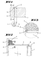
- An alternative embodiment of the dispensing spout is 7 and 8, in which is equal to The embodiment described above has the free end 10 the dispensing nozzle 3 merges into a 90 ° elbow 11.
- the donation opening 2 is immediately in the Area of the free arch end formed so that this with the outer surface of the dispensing nozzle 3 in the opening plane at the apex line of the dispensing spout wall completes.
- the dispensing spout 3 can also have a dispensing opening 2, which are provided within the contour the uninfluenced outer surface of the dispensing spout 3 is trained.
- the donation opening 2 is this closed end 13 of the outlet nozzle 3 upstream and formed by a V-shaped incision.
- the V-shaped incision is chosen so that the V-leg about an angle of 90 ° include, with a valley line 14 the dispensing spout 3 about in the area of the body's longitudinal axis.
- the exit direction is also in this embodiment r of the local foam relative to the longitudinal extent the dispensing spout 3 angled by approximately 90 °.
- Output spout 3 is a fourth embodiment of an inventive one Output spout 3 shown, in which two opposite, one on the right Including angle to the longitudinal extent of the dispensing nozzle 3 Donation openings 2 are provided.
- Such Output spouts 3 can advantageously be used for Introduction of foam 4 in horizontal, for example Serve joints.
- the embodiment is the dispensing spout 3 as a plug-in part for placement on a standard, straight-line dispensing tube educated.
- the output nozzle 3 has this Execution from a tapered, preferably to the Internal cross-section of a straight-line dispensing tube adapted neck area 20, which in addition for locking with a screw-shaped External ribbing 21 is provided.
- the Output spout 3 in this version ends in a cranked section 22 at its free end the dispensing opening 2 is formed.
- the latter is here so that it is aligned with the outer surface of the Dispensing nozzle 3 in terms of opening level at the level of a vertex line the larger diameter spout wall completes.
- the exit direction closes accordingly r with the longitudinal extension of the dispensing nozzle 3 obtuse angle alpha, in the embodiment shown Is 135 °.
- the donation opening is oval 2.
- the tapered neck region 20 extends in the longitudinal direction be conically tapered.
- the illustrated embodiments of the dispensing spout 3 are in the same way, joint material such as.
Applications Claiming Priority (4)
| Application Number | Priority Date | Filing Date | Title |
|---|---|---|---|
| DE20009384 | 2000-05-25 | ||
| DE20009384U | 2000-05-25 | ||
| DE20104436U | 2001-03-15 | ||
| DE20104436U DE20104436U1 (de) | 2000-05-25 | 2001-03-15 | Zwei-Komponenten-Dose und Ausgabetülle für eine Zwei-Komponenten-Dose |
Publications (3)
| Publication Number | Publication Date |
|---|---|
| EP1157944A2 true EP1157944A2 (fr) | 2001-11-28 |
| EP1157944A3 EP1157944A3 (fr) | 2002-07-31 |
| EP1157944B1 EP1157944B1 (fr) | 2007-03-07 |
Family
ID=26056289
Family Applications (1)
| Application Number | Title | Priority Date | Filing Date |
|---|---|---|---|
| EP01112455A Expired - Lifetime EP1157944B1 (fr) | 2000-05-25 | 2001-05-22 | Récipient pour produits à un ou deux composants avec tube de distribution |
Country Status (3)
| Country | Link |
|---|---|
| EP (1) | EP1157944B1 (fr) |
| AT (1) | ATE356051T1 (fr) |
| DE (1) | DE50112145D1 (fr) |
Citations (7)
| Publication number | Priority date | Publication date | Assignee | Title |
|---|---|---|---|---|
| DE9400082U1 (de) * | 1994-01-04 | 1994-02-24 | Chen Chuan Wu | Leimauftrag-Werkzeugsatz für Schreiner |
| JPH09154914A (ja) * | 1995-12-07 | 1997-06-17 | Kanebo Ltd | 液体吐出容器 |
| JPH09193976A (ja) * | 1996-01-16 | 1997-07-29 | Seiichi Kitabayashi | 誤噴射を防止し得る噴射嘴 |
| JPH1066900A (ja) * | 1996-08-26 | 1998-03-10 | Earth Chem Corp Ltd | 噴霧器用ロングノズル |
| US5868324A (en) * | 1995-11-29 | 1999-02-09 | Sony Corporation | Nozzle for soldering apparatus |
| US5921446A (en) * | 1996-04-02 | 1999-07-13 | Homax Products, Inc. | Aerosol spray texturing systems and methods |
| DE19918957A1 (de) * | 1998-04-27 | 1999-11-04 | Colux Licht & Leichtbau | Verwendung einer Zweikammer-Aerosoldose sowie feuerhemmend ausgerüsteter Montageschaum |
-
2001
- 2001-05-22 DE DE50112145T patent/DE50112145D1/de not_active Expired - Lifetime
- 2001-05-22 AT AT01112455T patent/ATE356051T1/de not_active IP Right Cessation
- 2001-05-22 EP EP01112455A patent/EP1157944B1/fr not_active Expired - Lifetime
Patent Citations (7)
| Publication number | Priority date | Publication date | Assignee | Title |
|---|---|---|---|---|
| DE9400082U1 (de) * | 1994-01-04 | 1994-02-24 | Chen Chuan Wu | Leimauftrag-Werkzeugsatz für Schreiner |
| US5868324A (en) * | 1995-11-29 | 1999-02-09 | Sony Corporation | Nozzle for soldering apparatus |
| JPH09154914A (ja) * | 1995-12-07 | 1997-06-17 | Kanebo Ltd | 液体吐出容器 |
| JPH09193976A (ja) * | 1996-01-16 | 1997-07-29 | Seiichi Kitabayashi | 誤噴射を防止し得る噴射嘴 |
| US5921446A (en) * | 1996-04-02 | 1999-07-13 | Homax Products, Inc. | Aerosol spray texturing systems and methods |
| JPH1066900A (ja) * | 1996-08-26 | 1998-03-10 | Earth Chem Corp Ltd | 噴霧器用ロングノズル |
| DE19918957A1 (de) * | 1998-04-27 | 1999-11-04 | Colux Licht & Leichtbau | Verwendung einer Zweikammer-Aerosoldose sowie feuerhemmend ausgerüsteter Montageschaum |
Non-Patent Citations (3)
| Title |
|---|
| PATENT ABSTRACTS OF JAPAN vol. 1997, no. 10, 31. Oktober 1997 (1997-10-31) & JP 09 154914 A (KANEBO LTD;KEY TRANDING CO LTD), 17. Juni 1997 (1997-06-17) * |
| PATENT ABSTRACTS OF JAPAN vol. 1997, no. 11, 28. November 1997 (1997-11-28) & JP 09 193976 A (KITABAYASHI SEIICHI;MARUICHI:KK), 29. Juli 1997 (1997-07-29) * |
| PATENT ABSTRACTS OF JAPAN vol. 1998, no. 08, 30. Juni 1998 (1998-06-30) & JP 10 066900 A (EARTH CHEM CORP LTD), 10. März 1998 (1998-03-10) * |
Also Published As
| Publication number | Publication date |
|---|---|
| DE50112145D1 (de) | 2007-04-19 |
| ATE356051T1 (de) | 2007-03-15 |
| EP1157944B1 (fr) | 2007-03-07 |
| EP1157944A3 (fr) | 2002-07-31 |
Similar Documents
| Publication | Publication Date | Title |
|---|---|---|
| DE19603285B4 (de) | Intramedullärer Nagel | |
| DE69629970T2 (de) | Stilett und seine Verbinder | |
| DE19948409C1 (de) | Vorrichtung zur Handhabung wenigstens eines Führungsdrahts zur Führung eines interventionellen medizinischen Instruments oder zur Handhabung eines Katheterschafts bei interventionellen medizinischen Techniken | |
| EP0668048B1 (fr) | Dispositif de prise de sang | |
| WO2000044317A1 (fr) | Implant intervertebral | |
| DE69824734T2 (de) | Katheterventil | |
| DE2227193A1 (de) | Nasenkanüle | |
| DE2800362A1 (de) | Endoskop | |
| EP0399234A1 (fr) | Ampoule | |
| DE3729840C1 (de) | Markraum - Verriegelungsnagel | |
| DE3540725A1 (de) | Tamponeinsetzer | |
| EP0529341A1 (fr) | Trousse pour l'anestésie | |
| DE3217476C2 (fr) | ||
| EP3157448B1 (fr) | Dispositif pour l'introduction d'un support ou d'un instrument dans le corps humain, en particulier port ou trocart pour l' oeil humain | |
| EP0501365A2 (fr) | Procédé et dispositif de dosage d'une substance fluide à partir d'un réservoir d'alimention | |
| EP1157944A2 (fr) | Récipient pour produits à un ou deux composants avec tube de distribution | |
| DE102008043811A1 (de) | Haushaltsgerät mit Lagerzapfen mit Verdrehsicherung für Lagerbuchse | |
| DE4320186A1 (de) | Dünndarmsonde | |
| DE102004005866A1 (de) | Entfernbare Türfeststellvorrichtung | |
| DE102009032188B4 (de) | Vorrichtung zum Einführen eines Mediums oder eines Instruments in den menschlichen Körper | |
| DE60028449T2 (de) | Vorrichtung zur Intubation des Tränenkanals | |
| DE3824244C2 (de) | Anordnung mit einem Drainagerohr, einem Mandrin und einer Hilfsschiene | |
| DE19546580C1 (de) | Zugangsstück zur weitgehend luftfreien Flüssigkeitszuleitung und/oder Flüssigkeitsentnahme | |
| DE2716783C3 (de) | Durch ein Abbrechteil verschlossener Anschlußstutzen | |
| DE4330089C2 (de) | Katheter |
Legal Events
| Date | Code | Title | Description |
|---|---|---|---|
| PUAI | Public reference made under article 153(3) epc to a published international application that has entered the european phase |
Free format text: ORIGINAL CODE: 0009012 |
|
| AK | Designated contracting states |
Kind code of ref document: A2 Designated state(s): AT BE CH CY DE DK ES FI FR GB GR IE IT LI LU MC NL PT SE TR |
|
| AX | Request for extension of the european patent |
Free format text: AL;LT;LV;MK;RO;SI |
|
| PUAL | Search report despatched |
Free format text: ORIGINAL CODE: 0009013 |
|
| AK | Designated contracting states |
Kind code of ref document: A3 Designated state(s): AT BE CH CY DE DK ES FI FR GB GR IE IT LI LU MC NL PT SE TR |
|
| AX | Request for extension of the european patent |
Free format text: AL;LT;LV;MK;RO;SI |
|
| 17P | Request for examination filed |
Effective date: 20030116 |
|
| AKX | Designation fees paid |
Designated state(s): AT BE CH CY DE DK ES FI FR GB GR IE IT LI LU MC NL PT SE TR |
|
| 17Q | First examination report despatched |
Effective date: 20030625 |
|
| RAP1 | Party data changed (applicant data changed or rights of an application transferred) |
Owner name: RPM IRELAND IP LTD. |
|
| GRAP | Despatch of communication of intention to grant a patent |
Free format text: ORIGINAL CODE: EPIDOSNIGR1 |
|
| GRAS | Grant fee paid |
Free format text: ORIGINAL CODE: EPIDOSNIGR3 |
|
| GRAA | (expected) grant |
Free format text: ORIGINAL CODE: 0009210 |
|
| AK | Designated contracting states |
Kind code of ref document: B1 Designated state(s): AT BE CH CY DE DK ES FI FR GB GR IE IT LI LU MC NL PT SE TR |
|
| PG25 | Lapsed in a contracting state [announced via postgrant information from national office to epo] |
Ref country code: IE Free format text: LAPSE BECAUSE OF FAILURE TO SUBMIT A TRANSLATION OF THE DESCRIPTION OR TO PAY THE FEE WITHIN THE PRESCRIBED TIME-LIMIT Effective date: 20070307 Ref country code: FI Free format text: LAPSE BECAUSE OF FAILURE TO SUBMIT A TRANSLATION OF THE DESCRIPTION OR TO PAY THE FEE WITHIN THE PRESCRIBED TIME-LIMIT Effective date: 20070307 Ref country code: NL Free format text: LAPSE BECAUSE OF FAILURE TO SUBMIT A TRANSLATION OF THE DESCRIPTION OR TO PAY THE FEE WITHIN THE PRESCRIBED TIME-LIMIT Effective date: 20070307 |
|
| REG | Reference to a national code |
Ref country code: GB Ref legal event code: FG4D Free format text: NOT ENGLISH |
|
| REG | Reference to a national code |
Ref country code: CH Ref legal event code: EP |
|
| REF | Corresponds to: |
Ref document number: 50112145 Country of ref document: DE Date of ref document: 20070419 Kind code of ref document: P |
|
| REG | Reference to a national code |
Ref country code: IE Ref legal event code: FG4D Free format text: LANGUAGE OF EP DOCUMENT: GERMAN |
|
| PGFP | Annual fee paid to national office [announced via postgrant information from national office to epo] |
Ref country code: NL Payment date: 20070508 Year of fee payment: 7 |
|
| PGFP | Annual fee paid to national office [announced via postgrant information from national office to epo] |
Ref country code: AT Payment date: 20070509 Year of fee payment: 7 Ref country code: BE Payment date: 20070509 Year of fee payment: 7 |
|
| PGFP | Annual fee paid to national office [announced via postgrant information from national office to epo] |
Ref country code: CH Payment date: 20070510 Year of fee payment: 7 Ref country code: DK Payment date: 20070510 Year of fee payment: 7 |
|
| GBT | Gb: translation of ep patent filed (gb section 77(6)(a)/1977) |
Effective date: 20070425 |
|
| PG25 | Lapsed in a contracting state [announced via postgrant information from national office to epo] |
Ref country code: SE Free format text: LAPSE BECAUSE OF FAILURE TO SUBMIT A TRANSLATION OF THE DESCRIPTION OR TO PAY THE FEE WITHIN THE PRESCRIBED TIME-LIMIT Effective date: 20070607 |
|
| PG25 | Lapsed in a contracting state [announced via postgrant information from national office to epo] |
Ref country code: ES Free format text: LAPSE BECAUSE OF FAILURE TO SUBMIT A TRANSLATION OF THE DESCRIPTION OR TO PAY THE FEE WITHIN THE PRESCRIBED TIME-LIMIT Effective date: 20070618 |
|
| PG25 | Lapsed in a contracting state [announced via postgrant information from national office to epo] |
Ref country code: PT Free format text: LAPSE BECAUSE OF FAILURE TO SUBMIT A TRANSLATION OF THE DESCRIPTION OR TO PAY THE FEE WITHIN THE PRESCRIBED TIME-LIMIT Effective date: 20070807 |
|
| ET | Fr: translation filed | ||
| NLV1 | Nl: lapsed or annulled due to failure to fulfill the requirements of art. 29p and 29m of the patents act | ||
| REG | Reference to a national code |
Ref country code: IE Ref legal event code: FD4D |
|
| PGFP | Annual fee paid to national office [announced via postgrant information from national office to epo] |
Ref country code: GB Payment date: 20070509 Year of fee payment: 7 |
|
| PLBE | No opposition filed within time limit |
Free format text: ORIGINAL CODE: 0009261 |
|
| STAA | Information on the status of an ep patent application or granted ep patent |
Free format text: STATUS: NO OPPOSITION FILED WITHIN TIME LIMIT |
|
| PG25 | Lapsed in a contracting state [announced via postgrant information from national office to epo] |
Ref country code: DK Free format text: LAPSE BECAUSE OF FAILURE TO SUBMIT A TRANSLATION OF THE DESCRIPTION OR TO PAY THE FEE WITHIN THE PRESCRIBED TIME-LIMIT Effective date: 20070307 Ref country code: MC Free format text: LAPSE BECAUSE OF NON-PAYMENT OF DUE FEES Effective date: 20070531 |
|
| 26N | No opposition filed |
Effective date: 20071210 |
|
| PG25 | Lapsed in a contracting state [announced via postgrant information from national office to epo] |
Ref country code: IT Free format text: LAPSE BECAUSE OF FAILURE TO SUBMIT A TRANSLATION OF THE DESCRIPTION OR TO PAY THE FEE WITHIN THE PRESCRIBED TIME-LIMIT Effective date: 20070307 Ref country code: GR Free format text: LAPSE BECAUSE OF FAILURE TO SUBMIT A TRANSLATION OF THE DESCRIPTION OR TO PAY THE FEE WITHIN THE PRESCRIBED TIME-LIMIT Effective date: 20070608 |
|
| PGFP | Annual fee paid to national office [announced via postgrant information from national office to epo] |
Ref country code: FR Payment date: 20070508 Year of fee payment: 7 |
|
| BERE | Be: lapsed |
Owner name: RPM IRELAND IP LTD. Effective date: 20080531 |
|
| REG | Reference to a national code |
Ref country code: CH Ref legal event code: PL |
|
| GBPC | Gb: european patent ceased through non-payment of renewal fee |
Effective date: 20080522 |
|
| PG25 | Lapsed in a contracting state [announced via postgrant information from national office to epo] |
Ref country code: LI Free format text: LAPSE BECAUSE OF NON-PAYMENT OF DUE FEES Effective date: 20080531 Ref country code: CH Free format text: LAPSE BECAUSE OF NON-PAYMENT OF DUE FEES Effective date: 20080531 |
|
| PG25 | Lapsed in a contracting state [announced via postgrant information from national office to epo] |
Ref country code: AT Free format text: LAPSE BECAUSE OF NON-PAYMENT OF DUE FEES Effective date: 20080522 |
|
| REG | Reference to a national code |
Ref country code: FR Ref legal event code: ST Effective date: 20090119 |
|
| PG25 | Lapsed in a contracting state [announced via postgrant information from national office to epo] |
Ref country code: BE Free format text: LAPSE BECAUSE OF NON-PAYMENT OF DUE FEES Effective date: 20080531 |
|
| PG25 | Lapsed in a contracting state [announced via postgrant information from national office to epo] |
Ref country code: FR Free format text: LAPSE BECAUSE OF NON-PAYMENT OF DUE FEES Effective date: 20080602 |
|
| PG25 | Lapsed in a contracting state [announced via postgrant information from national office to epo] |
Ref country code: GB Free format text: LAPSE BECAUSE OF NON-PAYMENT OF DUE FEES Effective date: 20080522 |
|
| PG25 | Lapsed in a contracting state [announced via postgrant information from national office to epo] |
Ref country code: CY Free format text: LAPSE BECAUSE OF FAILURE TO SUBMIT A TRANSLATION OF THE DESCRIPTION OR TO PAY THE FEE WITHIN THE PRESCRIBED TIME-LIMIT Effective date: 20070307 |
|
| PG25 | Lapsed in a contracting state [announced via postgrant information from national office to epo] |
Ref country code: LU Free format text: LAPSE BECAUSE OF NON-PAYMENT OF DUE FEES Effective date: 20070522 |
|
| PG25 | Lapsed in a contracting state [announced via postgrant information from national office to epo] |
Ref country code: TR Free format text: LAPSE BECAUSE OF FAILURE TO SUBMIT A TRANSLATION OF THE DESCRIPTION OR TO PAY THE FEE WITHIN THE PRESCRIBED TIME-LIMIT Effective date: 20070307 |
|
| PGFP | Annual fee paid to national office [announced via postgrant information from national office to epo] |
Ref country code: DE Payment date: 20160725 Year of fee payment: 16 |
|
| REG | Reference to a national code |
Ref country code: DE Ref legal event code: R119 Ref document number: 50112145 Country of ref document: DE |
|
| PG25 | Lapsed in a contracting state [announced via postgrant information from national office to epo] |
Ref country code: DE Free format text: LAPSE BECAUSE OF NON-PAYMENT OF DUE FEES Effective date: 20171201 |